patent · US5419877
Acoustic barrier separator
30 May 1995
Page 1 — bibliographic record
III IIHIIIHIIII US005419877A
United States Patent (19) 11 Patent Number: 5,419,877 Goforth et al. 45) Date of Patent: May 30, 1995 54 ACOUSTIC BARRIER SEPARATOR OTHER PUBLICATIONS 75 Inventors: Robert R. Goforth, Encinitas; Tihiro Hueter & Bolt, "Physical Mechanisms for Sonic Process Ohkawa, La Jolla, both of Calif. ing', SONICS, Techniques for the use of Sound and Ul (73) Assignee: General Atomics, San Diego, Calif. trasound in Engineering and Science, pp. 220-225, John Wiley & Sons, Inc. New York (Copyright 1955).
21 Appl. No.: 123,635 Reethof, "Acoustic Agglomeration of Power Plant Fly Ash for Environmental and Hot Gas Clean-up', Trans 22 Filed: Sep. 17, 1993 actions of the ASME, vol. 110, pp. 552-557 (Oct. 1988). 51 Int. Cl....................... B01D 51/08; B01D 53/10; Richards, et al., "Applications of Acoustics in Ad vanced Energy Systems', The American Society of Me chanical Engineers, Winter Annual Meeting, San Fran (52) U.S. C. ...................................... 422/177; 55/277; cisco, Calif., pp. 1-8 (Dec. 10-15, 1989). 55/DIG. 25; 96/150; 23/313 R; 422/127; Dyer, et al., "Acoustic Levitation by Oseen Drag”, J. 422/168; 422/217 Acoust Soc. Am., vol. 92:(4), Pt. 1, pp. 2207-2211 (Oct.
(58) Field of Search ............... 422/127, 128, 168, 177, 1992).
95/29, 107, 135, 137, 110; 423/210, 235, 244, Primary Examiner-Robert J. Warden 215.5; 23/313 R; 110/216 Assistant Examiner-L. M. Crawford
Attorney, Agent, or Firm-Fitch, Even, Tabin & 56) References Cited Flannery
1,120,682 12/1914 Bucher ............................ 422/213 X High temperature gas emissions from industrial power 3,076,544 2/1963 Bodine ......... plant or environmental clean-up processes are subjected
3,681,009 8/1972 to an acoustic waveform having second harmonic con 3,894,851 7/1975 on uno 95/219 tent and appropriate second harmonic phase shift to 4,302,431 11/1981 422/172 X impart a net acoustic Oseen force on particulate matter 4,319,891 3/1982 ow 95/29 contained in the gas for removal of said matter. Particu 4,475,921 10/1984 . 23/313 R late matter of 1 micron radius is positively excluded, 4,529,422 7/1985 wo 55/270 while smaller particles are agglomerated by the sound 4,848,656 7/1989 239/2.1 wave. The acoustic waveform further enhances both 4,948,497 8/1990 209/1 sorption of injected sorbent particles for removal of 5,059,404 10/1991 ... 423/201 5,133,297 7/1992 ... 122/4 D sulfur oxides, and the efficiency of an in-line catalytic 5,197,399 3/1993 ... 110/345 converter for removal of nitrogen oxides. The invention 5,205,728 4/1993 Mansour ................................. 431/1 improves overall removal efficiency, can operate at very high temperatures, and does not produce any sec
FOREIGN PATENT DOCUMENTS ondary waste, such as filters.
1554949 4/1990 U.S.S.R. . 14 Claims, 5 Drawing Sheets
Page 2
Drawing sheet — no readable text.
Page 3
Drawing sheet — no readable text.
Page 4
Drawing sheet — no readable text.
Page 5
Drawing sheet — no readable text.
Page 6
SOUND PIPE
GAS
CLAMP
X ACOUSTIC DRIVER
FILTER Utt
SAS,
ABSORBER
CHAMBER
PRESSURE GAGE
, s GAS NLET AND REGULATOR 1 / f 706 (V)
RESERVOIR
SOLDS ff0 OUT fift f72
FLUIDZER CSX FLOW CONE MY CONTROLLER GAS
GAS NLE
TUBING SHUTOFF
MICROPHONE
SOUND
OSCiLLOSCOPE GLASS
MCROPHONE
POWER
SUPPLY
Page 7
cyclonic separators. These technologies represent a
ACOUSTC BARRIER SEPARATOR relatively high cost of installation and operation or simply cannot provide the performance required for
BACKGROUND OF THE INVENTION specific applications.
The present invention relates generally to methods 5 Cyclonic separators operate at high temperature, and apparatus for the removal of gas borne solids in a which desirably allows the high temperature flue gas to thermal treatment process by the use of acoustic forces. be used in downstream equipment. However, such sepa More particularly, the invention is directed to the use of rators only separate particles with diameters greater the acoustic force known as the Oseen force for the than 5 micrometers. Furthermore, cyclonic separators removal of particles from a high temperature flue gas. 10 are generally not efficient compared to other separator A large variety of industrial powerplant and environ technologies. In a cyclonic separator, gas is forced to mental clean-up purposes are served by high tempera spin in a containment vessel and it is by means of centrif ture processing of fuels and contaminants, respectively. ugal force that particles are spun outward to an outer A common malady of these high temperature processes 15 wall where they drop to a collection hopper. The cen is the production of a hot gas or vapor flow with an trifugal force which can be reasonably generated is undesirably high particulate content. A large number of insufficient to cause particles of a diameter of less than Superfund applications require remediation of contami 5 microns to spin outward to the outer wall, given the nated soil. Where these applications require handling of turbulent and viscous forces of the gas. Unfortunately, soils, as in excavation, conveyance, blending, thermal it has been shown that particles smaller than this, espe treatment, or deposition, engineers are faced with the 20 cially in the 1 micron range, are best absorbed and re problem of control of particulate emissions. Current tained by the human pulmonary system, and thus may stringent regulations place a ceiling on the level of par contribute to respiratory ailments such as bronchitis, ticulate emissions which will be tolerated from the likes emphysema and lung cancer.
of coal-fired power plant flues or environmental clean 25 Electrostatic precipitators came into commercial up emissions. Furthermore, it is desirable to remove service in the early 1900s. Literally hundreds of dis particulates from a high temperature gas flow where charge electrode configurations have been utilized. such particulates may have an abrasive effect on down Electrostatic precipitators capture dust or fly ash by stream equipment. For example, the flue gas from a charging the individual particles and then accelerating coal-fired boiler contains sulfur oxide gases, nitrogen oxide gases, and fly ash particulates which must be 30 them with in an electric field until they come into contact a grounded collecting surface. Agglomeration of destroyed or removed before the clean gas is released the particles occurs at the collecting surface which into the atmosphere. Preferably the treatment is com allows the resulting agglomerates to be mechanically pleted while the flue gas is at a high temperature such rapped or in some cases washed from the collecting that it can spin a turbine or preheat air, without the surfaces into the hoppers below each collecting field. abrasive effect of fly ash or the corrosive effect of acid 35 The efficiency of such precipitators is highly sensitive anhydride gases.
to particle resistivity. At the extremes of particle resis
High temperatures are also desirable in an application tivity, both low and high, precipitator efficiency is neg such as the remediation by an evaporation process of atively impacted. When particle resistivity is low, pre contaminated soil containing, for example, mercury.
Removal of the volatile component or contaminant 40 cipitator efficiency may degrade due to reentrainment such as mercury by such an evaporation process must of the collected dust. The combined effects of gas flow be carried out at a temperature above the dew point for and the weight of the collected material act to dislodge the volatile substance, to prevent its condensation on and reentrain collected material in the gas flow. Fur the fly ash. For example, in a flue gas containing a mix ther, when the collecting surfaces of conventional pre ture of mercury vapor, air, other vapors, and fly ash, the 45 cipitators are rapped, some of the collected dust cake is separation of the fly ash from the gas should take place redispersed in the gas stream as small particles. near 400 C. to prevent condensation of mercury on the With high particulate resistivity, a high voltage drop particulates. For a clay soil, many of the particulates in develops across the collected dust cake layer, resulting the fly ash will be below 1 micrometer in diameter. in the phenomenon know as "back ionization'. Back As another example, mixed wastes, consisting of ma SO ionization impedes the normal flow of negative ions, or terials contaminated with both radioactive constituents positively discharges dust particles, ejecting collected and hazardous non-radioactive constituents, are desir particulates from the dust cake. In severe cases, the ably treated at high temperature. This is because it is precipitation process essentially stops. highly desirable to separate radioactively contaminated Unfortunately, at high temperatures, particulate resis constituents from hazardous non-radioactive constitu 55 tivity generally decreases. Consequently, electrostatic ents since there is no available disposal means for mixed precipitators cannot effectively operate at high temper wastes, whereas radioactive wastes and hazardous atures.
wastes can be individually managed through currently Water spray scrubbers cannot operate above the available and approved methods. In a mixed waste pro steam point of 100 C. Baghouse filters also cannot cess, gas flow will entrain solid particulates carrying operate at high temperatures. Furthermore, baghouse radioactive contaminants. To prevent recontamination filters are susceptible to tearing. Finally, filters and of these particulates by gas-entrained hazardous con water spray scrubbers result in an increase in the vol densables, a separation must be effected attemperatures ume of waste materials, because the filters and water well above the condensation point of the hazardous must be collected and disposed of as waste. compound so as to avoid generation of a mixed waste In a flue gas containing sulphur oxide gases and nitro residue. gen oxide gases, such as from a coal-fired boiler, the Present particulate containment technologies include injection of sorbent particles and ammonia gas ahead of filtration, scrubbing, electrostatic precipitation, and a high temperature fabric filter has been practiced. The
Page 8
sorbent particles remove the sulphur oxide gases from gas upstream of the separator chamber to sweep up the flue gas and are themselves removed by the filter sulphur oxides and nitrogen oxides in the flue gas, and along with the fly ash. The filter holds a catalyst for which are subsequently removed at the acoustic barrier conversion of nitrogen oxides and ammonia to nitrogen or in a downstream catalytic converter. By means of the and water. The fabric filters include the high cost of 5 rapid and frequent relative motion of the gas molecules continuous fiber ceramic sleeves and are susceptible to with respect to the sorbent and catalyst particles in the clogging by condensable vapors. The destruction or flue gas, induced by the acoustic waveform, sorbents removal efficiencies achieved with the filter system are and catalysts effectively sweep out greater amounts of only 70% for sulphur oxides, 90% for nitrogen oxides, such noxious gases.
and 99% for particulates. 10 No secondary waste is created by the present inven There is a need in high temperature thermal processes tion, in the form of water spray and filters. The inven employed in both the powerplantindustry and environ tion may be operated effectively at very high tempera mental clean-up industry for improved means of reduc tures. Hazardous volatiles may thereby be prevented ing the particulate and hazardous waste contents of a from condensing on collected particles, simplifying high temperature flue gas. In particular, there is a need 15 remediation processes. Likewise, a relatively abrasive for an efficient treatment which effectively removes small particles and enhances the action of sorbents and free gas may be delivered to a downstream turbine or catalysts typically used for removal of sulfur oxides and efficiency.at a high temperature for maximum turbine the like nitrogen oxides, which treatment is completed while The invention delivers sonic energy at a reasonable the flue gas is at a high temperature, such that the flue 20 power cost, achieves high rates of particulate removal, gas may be used in downstream equipment without the enhances abrasive effect of fly ash or the corrosive effect of acidic oxide gases,thecanremoval
of sulphur oxide and nitrogen operated at very high temperatures, gases. Finally, there is a need for a treatment which will and does not produce any secondary waste. not result in an increased volume of hazardous waste which must be disposed of. 25 BRIEF DESCRIPTION OF THE DRAWINGS SUMMARY OF THE INVENTION In the drawings:
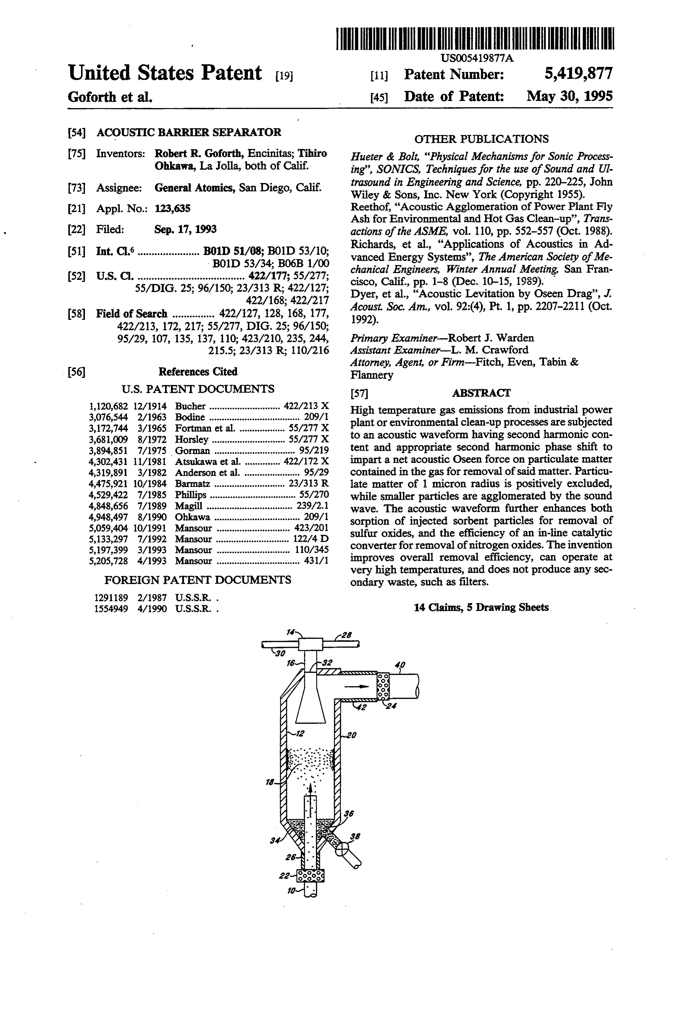
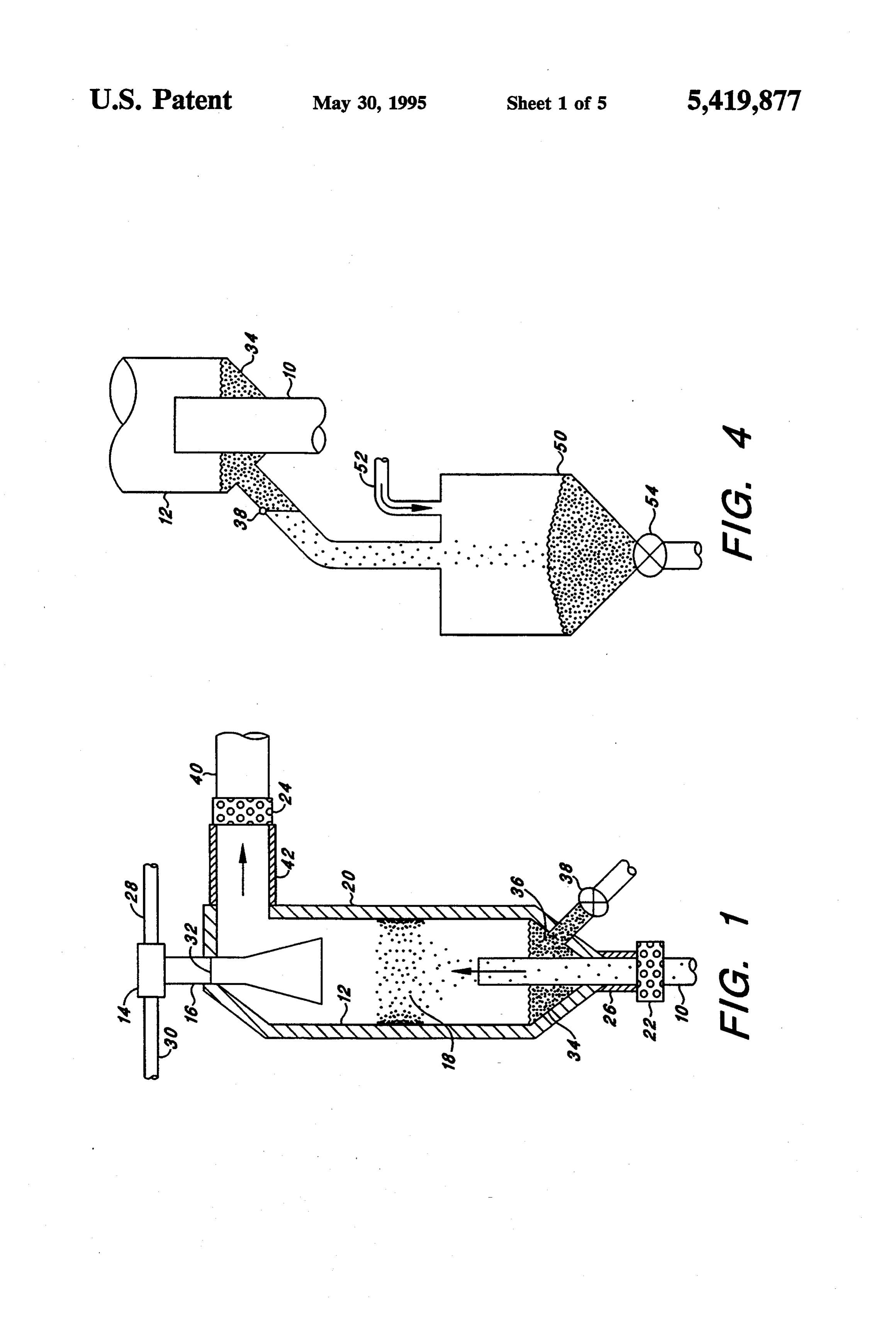
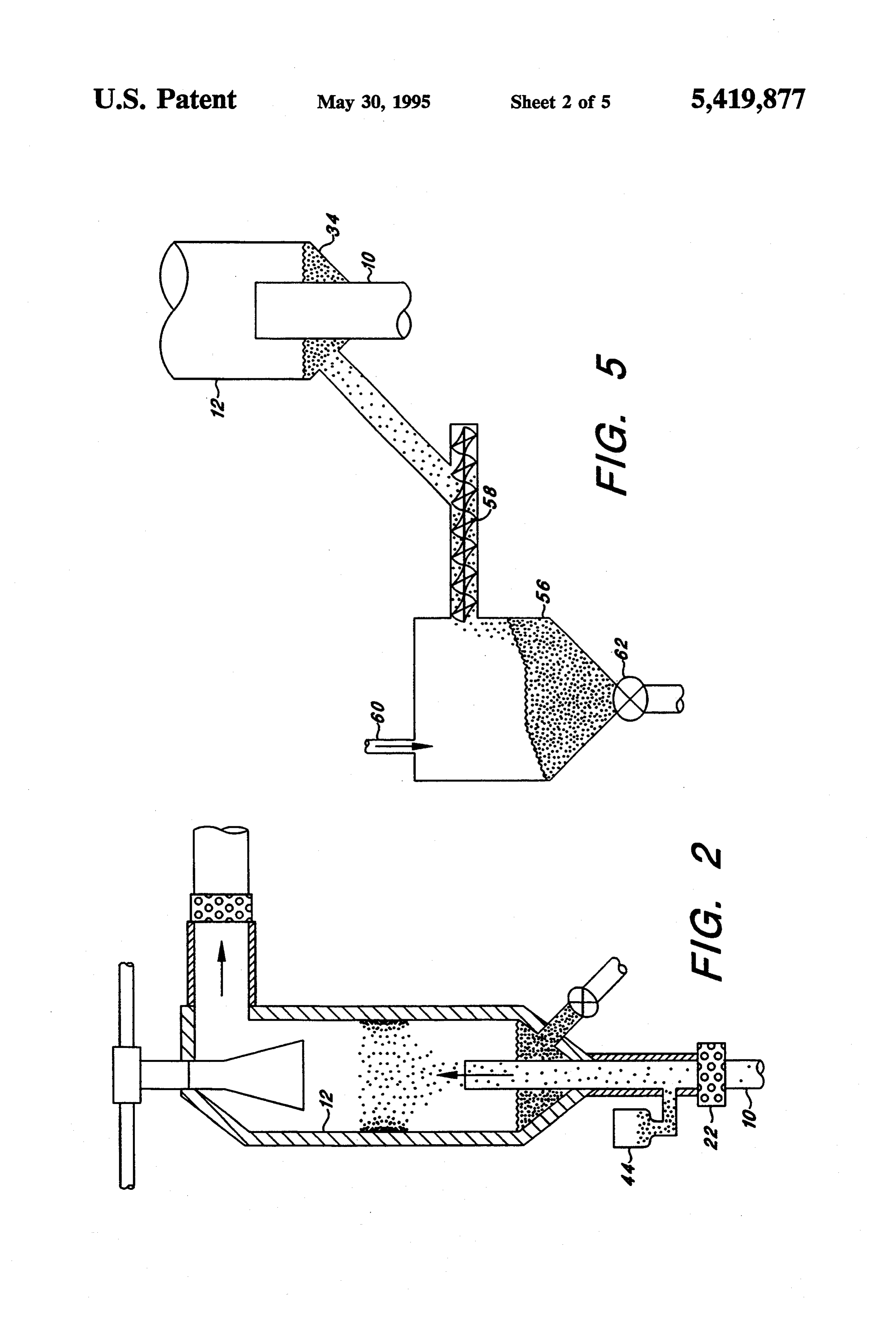
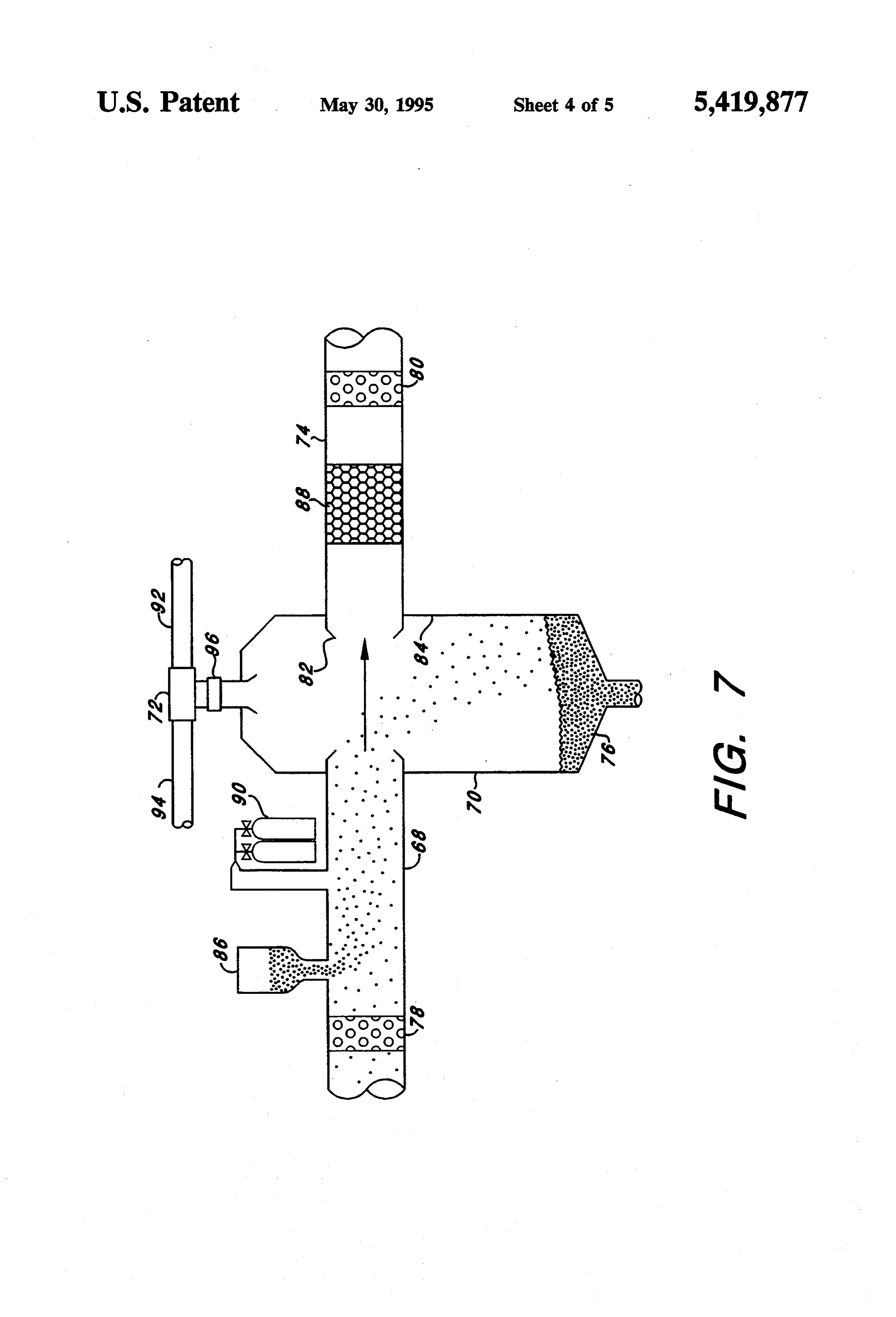
The present invention provides an acoustic barrier rator FIG. 1 is a sectional view of an acoustic barrier sepa separator and acoustic enhancement treatment for use according to the present invention; in substantially and efficiently removing small- and 30 FIG. 2 is a sectional view of an acoustic barrier sepa larger-diameter fly ash and hazardous volatiles from rator with a sorbent injection system; high temperature gas emissions, such as the flue gas rator FIG. 3 is a sectional view of an acoustic barrier sepa produced in a coal-fired boiler or high temperature with a catalytic converter system; FIG. 4 is a sectional view of a vertical embodiment of remediation process. The invention is particularly suit a collected able for use in efficiently removing small particulates at 35 solids conveyor system for the present in high temperatures that are not removed efficiently by vention; FIG. 5 is a sectional view of a horizontal embodiment prior art separation means at high temperatures.
According to the invention, the flue gas is subjected of a collected solids conveyor system for the present in a separator chamber to the output of an acoustic invention;
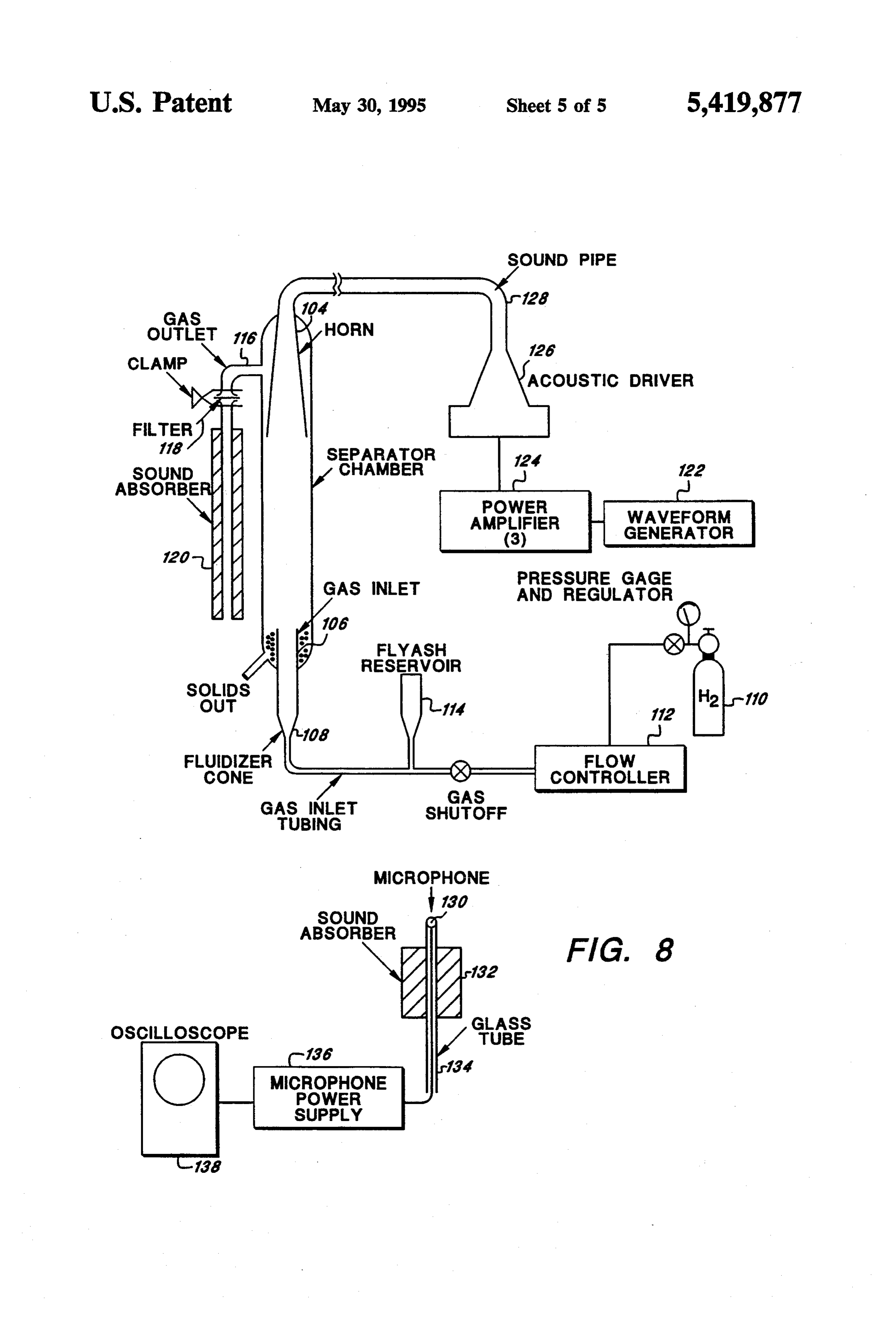
source, the amplitude, frequency and phase of which FIG. 6 is a sectional view of a purge-gas system for are selected to provide an Oseen force which acts on use in the present invention; the fly ash particulates in the gas stream. The acoustic FIG. 7 is a sectional view of another embodiment of waveform exerts over time a net Oseen force on the an acoustic barrier separator according to the present particulates, which may be directed against the gas flow invention; and or may be directed laterally to the gas flow. An Oseen 45 FIG. 8 schematically depicts a test configuration used force directed against the gas flow overcomes the drag to test the present invention.
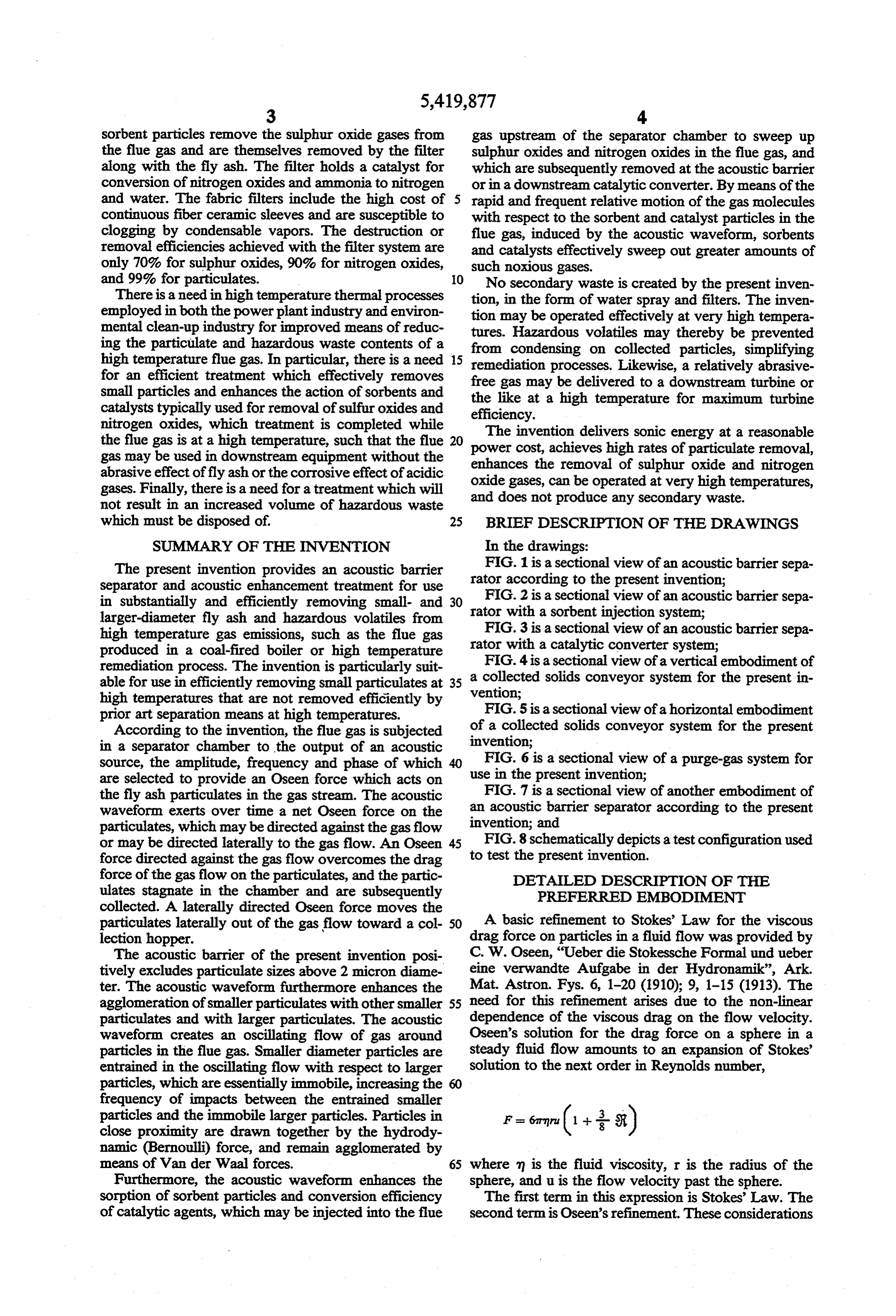
force of the gas flow on the particulates, and the partic DETALED DESCRIPTION OF THE ulates stagnate in the chamber and are subsequently PREFERRED EMBODIMENT collected. A laterally directed Oseen force moves the particulates laterally out of the gas flow toward a col 50 A basic refinement to Stokes' Law for the viscous lection hopper. drag force on particles in a fluid flow was provided by The acoustic barrier of the present invention posi C. W. Oseen, “Ueber die Stokessche Formal undueber tively excludes particulate sizes above 2 micron diame eine verwandte Aufgabe in der Hydronamik', Ark. ter. The acoustic waveform furthermore enhances the Mat. Astron. Fys. 6, 1-20 (1910); 9, 1-15 (1913). The agglomeration of smaller particulates with other smaller 55 need for this refinement arises due to the non-linear particulates and with larger particulates. The acoustic dependence of the viscous drag on the flow velocity. waveform creates an oscillating flow of gas around Oseen's solution for the drag force on a sphere in a particles in the flue gas. Smaller diameter particles are steady fluid flow amounts to an expansion of Stokes' entrained in the oscillating flow with respect to larger solution to the next order in Reynolds number, particles, which are essentially immobile, increasing the frequency of impacts between the entrained smaller particles and the immobile larger particles. Particles in close proximity are drawn together by the hydrody namic (Bernoulli) force, and remain agglomerated by
means of Van der Waal forces. 65 where m is the fluid viscosity, r is the radius of the Furthermore, the acoustic waveform enhances the sphere, and u is the flow velocity past the sphere. sorption of sorbent particles and conversion efficiency The first term in this expression is Stokes' Law. The of catalytic agents, which may be injected into the flue second termis Oseen's refinement. These considerations
Page 9
for the drag force on a sphere due to steadily flowing The maximum positive force away from the acoustic fluid can be adapted to determine the average drag source thus occurs for a phase angle of -7T/2. force on a sphere in an oscillating fluid flow associated The frequency spectrum of the acoustic wave used in with a traveling acoustic wave. Provided that the peak the present invention preferably comprises a basic fre Reynolds number of this flow is small, and the acoustic quency and a superimposed frequency of twice the wave length is much larger than the radius of the basic frequency value and phase shifted in relation to sphere, the results for a steadily flowing fluid are ex the basic frequency by - T/2. This phase shift maxi pected to apply for a traveling acoustic wave. The flow mizes the Oseen force in a direction away from the velocity u past a sphere in an acoustic field of a travel O acoustic source. However, any phase shift between ing sound wave is a periodic function of time and the -7t/2 and zero will create an Oseen force away from force experienced by the sphere will also be a function the acoustic source, if other considerations demand of time. It is the time average of this force that is of such a phase shift.
Turning now to FIG. 1, an acoustic separator accord interest. When averaged over a complete cycle of any purely periodic flow, the first term in the above equa 15 ing to one embodiment of the present invention is shown to comprise a gas introduction flue 10 for deliv tion vanishes since the time averaged fluid velocity of ery of a high temperature flue gas containing solid par such a flow is zero. The second term is ticulates or fly ash, sulfur oxide gases, nitrogen oxide gases, or a combination thereof, into a chamber 12, where an acoustic waveform is directed from a siren 14 20 or set of sirens via a linearly tapering horn 16 against the where p is fluid density. This term can yield a finite gasflow. Particulates 18 are stagnated in the flow by the average value depending on the time average of the Oseen force. Chamber 12 preferably has a larger cross product uu. The value of this Oseen-type moment section than either flue 10 or linearly tapering horn 16, and is made from a material resistant to high tempera depends on the Fourier content and intensity of the 25 tures.
acoustic wave. For symmetric velocity waveforms, the art,The siren 14 is preferably a gas siren as known in capable of delivering enough power to provide e.g., a pure sine wave, the Oseen-type moment is zero a sufficient Oseen force to overcome the drag force of and the Oseen term in the force expression vanishes. the gas.
For harmonically distorted waveforms, this moment An insulating layer 20 is employed around chamber can have a finite value implying the existence of a 30 12 for reducing the amount of noise to which workers in steady acoustic force on the sphere. The magnitude and the area of the chamber are subject. Since the chamber direction of this force will depend on the amplitudes is at a high temperature during use, a high-temperature and relative phases of the Fourier components of the resistant, sound-damping material, such as fiber glass, velocity waveform. may be used to encase the chamber 12 and the conduits The acoustic Oseen effect is only one of the steady 35 leading into and out of the chamber. Alternatively, the forces an acoustic field exerts on an object. Other steady chamber may be contained and supported in an outer sonic forces include: (a) the hydrodynamic attraction jacketing chamber, where air has been withdrawn from between objects (agglomeration) due to the periodic the space between the jacketing chamber and the sepa rush of fluid between them, (b) radiation pressure due to ration chamber 12, to provide a vacuum insulation. the scattering of the sound field by the object, and (c) 40 Mufflers 22 and 24 are also preferably located both the average Stokes' pressure due to a temperature de upstream and downstream from the chamber 12 to fur pendence of viscosity in the adiabatic compressions of a ther dampen the noise of the apparatus. Any muffler sound wave. For particles greater than 2 micrometers in knewn in the art which is suitable for the operating diameter in an Oseen-type, e.g., harmonically distorted, conditions described herein may be used. For example, progressive wave, the radiation pressure and the aver 45 one type of muffler that may be used is of the Helmholz age Stokes' force are small, compared to the Oseen type, which is well known in the art. Flue 10 may be force. The hydrodynamic attraction becomes important covered from muffler 22 to the chamber 12 with an only when the particle separation becomes small, com insulating jacket 26, such as fiber glass. pared to particle diameters, and is in part responsible for The temperature of the flue gas may be very high, for particle agglomeration according to this invention. A 50 example sufficiently high to prevent the condensation more complete appreciation of these force components of semi-volatile organics or other hazardous vapors on and their relationships is found with reference to T. F. the solid particulates. The acoustic waveform has sub Hueter and R. H. Bolt, Sonics, (John Wiley & Sons, stantial second harmonic content, preferably about New York, 1955). equal to the fundamental harmonic content, which is The Oseen force is dependent on the magnitude and 55 generated by shaping the apertures of the siren 14, or phase of the second harmonic component of the acous alternatively by providing in addition to a first set of tic wave. The particle velocity of the sound wave may siren apertures a second set of siren apertures emitting be written as: sound at twice the fundamental frequency emitted by the first set of apertures.
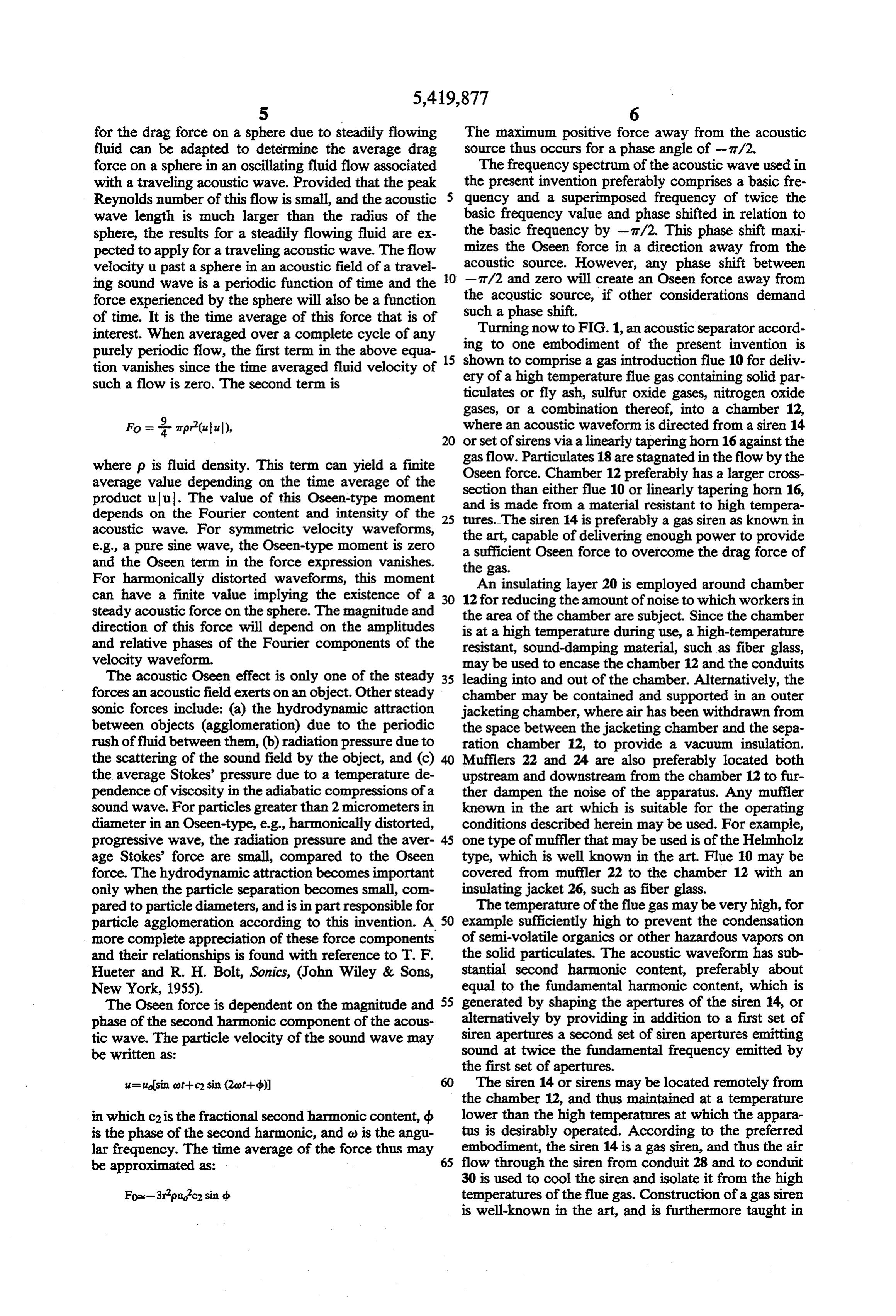
u- usin ot-c2 sin (2ot--d) The siren 14 or sirens may be located remotely from the chamber 12, and thus maintained at a temperature in which c2 is the fractional second harmonic content, cb lower than the high temperatures at which the appara is the phase of the second harmonic, and c) is the angu tus is desirably operated. According to the preferred lar frequency. The time average of the force thus may embodiment, the siren 14 is a gas siren, and thus the air be approximated as: 65 flow through the siren from conduit 28 and to conduit 30 is used to cool the siren and isolate it from the high
Foe-3r'puc2 sind temperatures of the flue gas. Construction of a gas siren is well-known in the art, and is furthermore taught in
Page 10
the Ph D thesis of F. G. Pla, “An Experimental and cated at the base of the chamber 12. The solids collec Theoretical Study of High Intensity, High Efficiency tion hopper 34 may be emptied of collected solids 36 by Sirens', Pennsylvania State University, 1987, available means of a discharge valve 38. Discharge valve 38 con from UMI Dissertation Services. trols the amount of solids maintained in the solids col The sound field from the siren is expanded through lection hopper 34, which amount is kept at a predeter an exponential horn and is then transmitted through an mined level to facilitate proper absorption of acoustic isolator 32 to attenuate the gas flow associated with the energy, as discussed below.
siren operation. A sheet of felted, woven and sintered Flue gas which is substantially free of solid particu stainless steel may be used as an isolator. The sound is lates exits the chamber 12 via an exit flue 40, which may then propagated through horn 16 before being radiated 10 covered with an insulating jacket 42 offiber glass or into the separation chamber. Horn 16 comprises an be the like, similar to insulating jacket 26. A muffler 24 inside shell and an outside shell, as is typical of such reduces noise coming out of the chamber 12 via flue 40. horns and well known in the art, and it is preferable that Separation chamber 12 is of sufficient size to accom the area of the annular region formed between the shells modate adequate gas flow for a desired application, and in cross-section is about the same as the cross-sectional 15 area of the flue 10. As a consequence, horn 16 may start may typically have a radius of about 0.3 meters or so. from an outer diameter approximately equivalent to Gas introduction flue 10 may then be about 0.1 meters that of flue 10, and expand to an outer diameter of al in radius or so. There should be sufficient space be tween the chamber walls and the flue 10 to allow col most that of the chamber 2. There should remain, however, sufficient space between the outer shell and 20 lected fly ash 36 to accumulate in hopper 34 to form an the chamber wall for adequate flow of flue gas beyond adequate sound absorbing layer. Therefore, the flue 10 horn 16. should also protrude in chamber 12 high enough to Preferably, as previously mentioned, the Oseen force allow for the accumulation of solids 36 to build to a is maximized away from the acoustic source by select depth sufficient for sound dampening purposes. A typi ing the phase of the second harmonic component to be 25 cal protrusion height is in the range of about 0.15-0.3 -T/2 radians with respect to the fundamental fre meters or so. Chamber 12 is preferably long, providing quency employed. The Oseen force on a particle is a length between the end of flue10 and the end of horn further maximized by selection of a fundamental fre 16 equivalent to a many times the diameter of the cham quency high enough that the particle inertia prevents ber. For example, the chamber may provide a distance entrainment in the acoustic wave oscillations. The parti 30 between flue 10 and horn 16 at least six times greater cle displacement is then less than the gas displacement than the diameter of the chamber. Horn 16 projects into in an acoustic cycle, and the particle “slips' with re chamber 12 for a distance sufficient to allow the turbu spect to the gas. For a particle diameter of 4 microme lent effect imparted to the gas by the transition from the ters, or less, the frequency is preferably greater than 5 chamber space to the space around the horn to die out. kHz to maximize the force. The fundamental frequency 35 For example, it is generally sufficient for horn 16 to employed in practice may be optimally selected by trial protrude about several horn outer diameters into the and error, or according to the requirements for acoustic chamber 12.
enhancement of sorption, agglomeration, or catalytic The Oseen force for these criteria may be written as: conversion, or according to the limits of gas siren de sign. Typically, the fundamental frequency may be in the audible range, and in particular in the range of 500
Hz to 8,000 Hz. FO st 32-A-
The power of the siren is selected such that the sec pc.
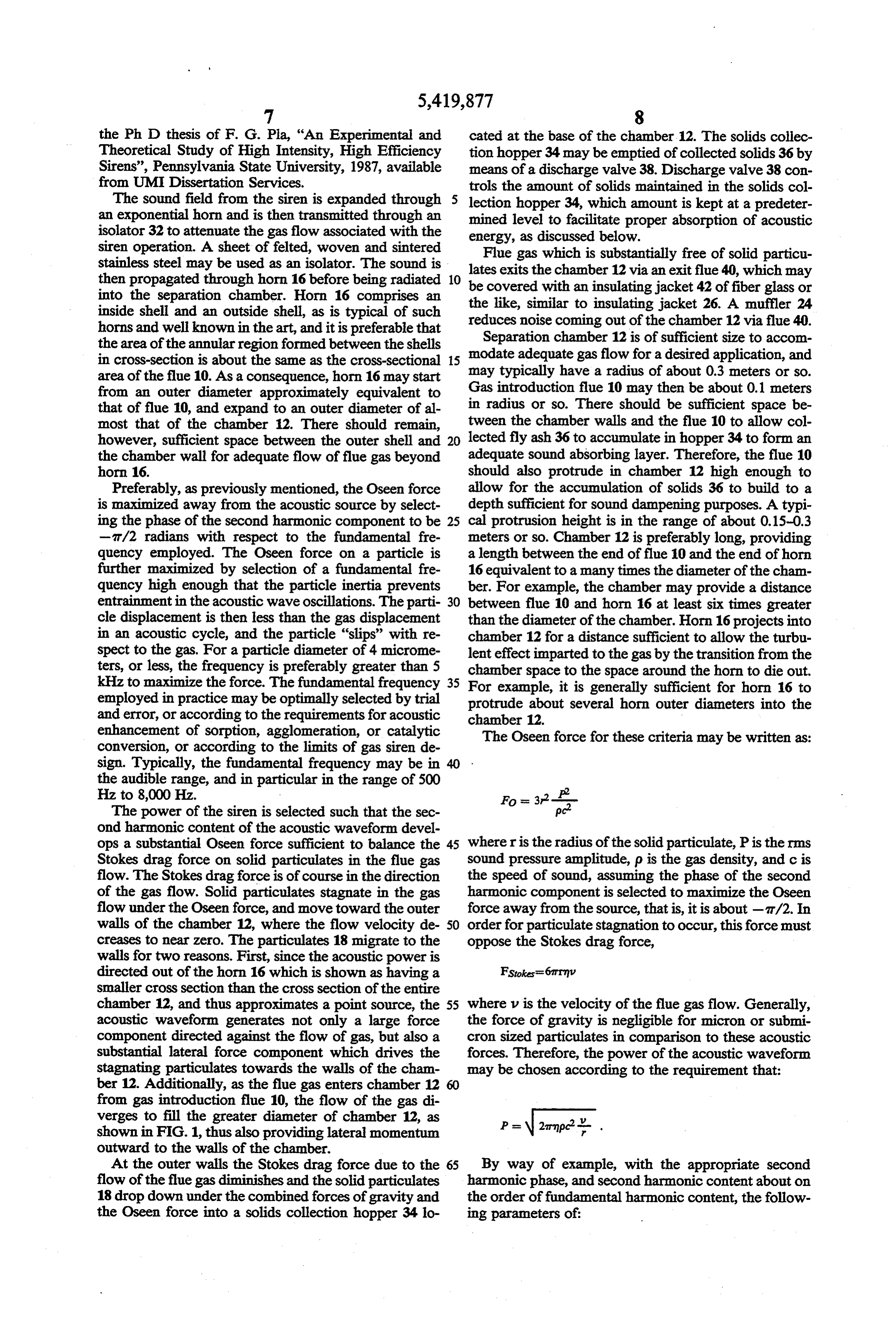
ond harmonic content of the acoustic waveform devel ops a substantial Oseen force sufficient to balance the 45 where ris the radius of the solid particulate, P is the rms Stokes drag force on solid particulates in the flue gas sound pressure amplitude, p is the gas density, and c is flow. The Stokes drag force is of course in the direction the speed of sound, assuming the phase of the second of the gas flow. Solid particulates stagnate in the gas harmonic component is selected to maximize the Oseen flow under the Oseen force, and move toward the outer force away from the source, that is, it is about -T/2. In walls of the chamber 12, where the flow velocity de 50 order for particulate stagnation to occur, this force must creases to near zero. The particulates 18 migrate to the oppose the Stokes drag force, walls for two reasons. First, since the acoustic power is directed out of the horn 16 which is shown as having a FStokes=6trav smaller cross section than the cross section of the entire chamber 12, and thus approximates a point source, the 55 where v is the velocity of the flue gas flow. Generally, acoustic waveform generates not only a large force the force of gravity is negligible for micron or submi component directed against the flow of gas, but also a cron sized particulates in comparison to these acoustic substantial lateral force component which drives the forces. Therefore, the power of the acoustic waveform stagnating particulates towards the walls of the cham may be chosen according to the requirement that: ber 12. Additionally, as the flue gas enters chamber 12 from gas introduction flue 10, the flow of the gas di verges to fill the greater diameter of chamber 12, as Ps \ 2rope? .
shown in FIG. 1, thus also providing lateral momentum outward to the walls of the chamber.
At the outer walls the Stokes drag force due to the 65 By way of example, with the appropriate second flow of the flue gas diminishes and the solid particulates harmonic phase, and second harmonic content about on 18 drop down under the combined forces of gravity and the order of fundamental harmonic content, the follow the Oseen force into a solids collection hopper 34 lo ing parameters of:
Page 11
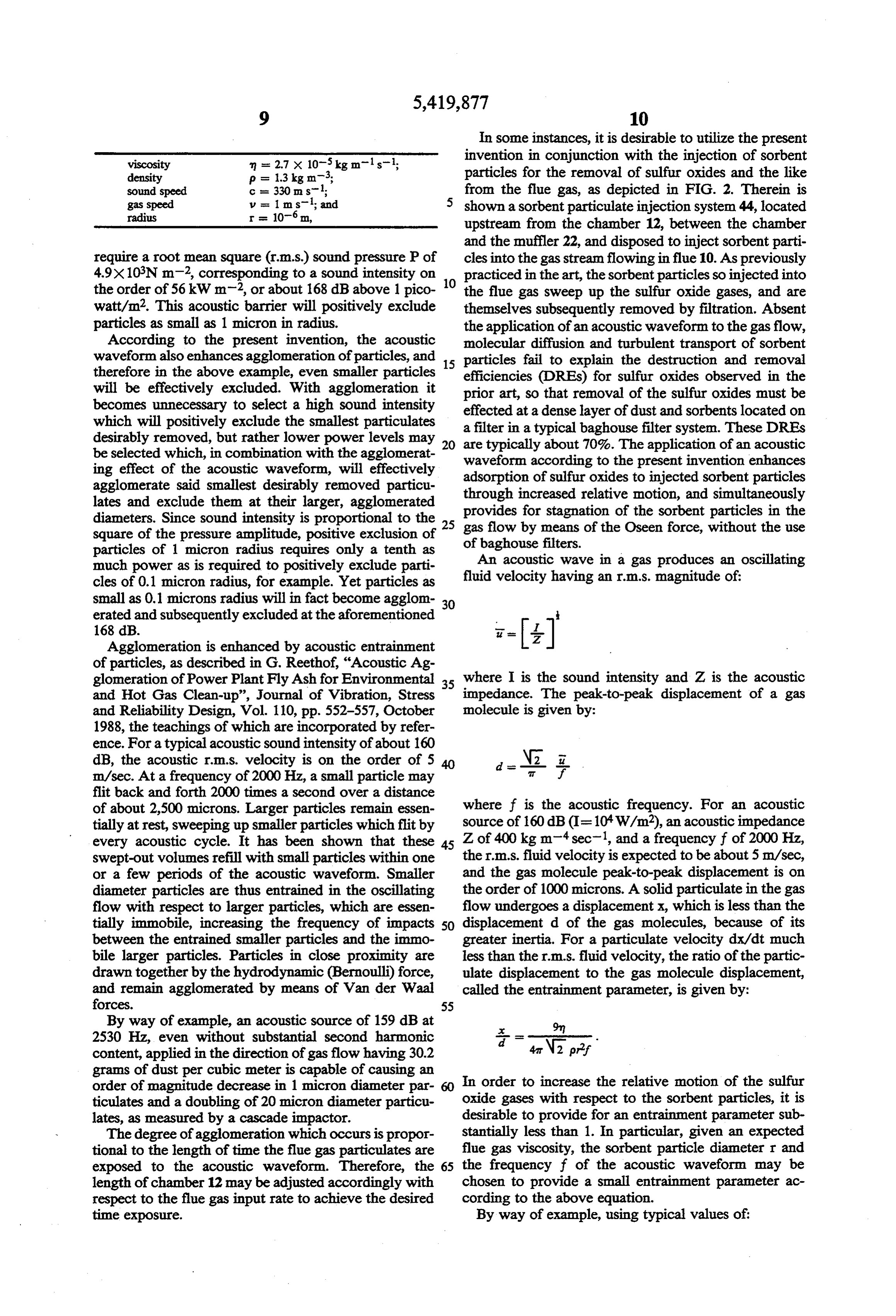
In some instances, it is desirable to utilize the present viscosity n = 2.7 x 10⁵ kg mis-l; invention in conjunction with the injection of sorbent density p = 1.3 kg m; particles for the removal of sulfur oxides and the like sound speed c = 330 ms; from the flue gas, as depicted in FIG. 2. Therein is gas speed v = 1 m st; and shown a sorbent particulate injection system 44, located radius r = 10.6m, upstream from the chamber 12, between the chamber and the muffler 22, and disposed to inject sorbent parti require a root mean square (r.m.s.) sound pressure P of cles into the gas streamflowing influe10. As previously 4.9x10N m2, corresponding to a sound intensity on practiced in the art, the sorbent particles so injected into the order of 56kW m-2, or about 168 dB above 1 pico 10 the flue gas sweep up the sulfur oxide gases, and are watt/m2. This acoustic barrier will positively exclude themselves subsequently removed by filtration. Absent particles as small as 1 micron in radius. the application of an acoustic waveform to the gas flow, According to the present invention, the acoustic molecular diffusion and turbulent transport of sorbent waveform also enhances agglomeration of particles, and 15 particles fail to explain the destruction and removal therefore in the above example, even smaller particles efficiencies (DREs) for sulfur oxides observed in the will be effectively excluded. With agglomeration it prior art, so that removal of the sulfur oxides must be becomes unnecessary to select a high sound intensity effected at a dense layer of dustandsorbents located on which will positively exclude the smallest particulates desirably removed, but rather lower power levels may 20 arefilter a in a typical baghouse filter system. These DREs typically about 70%. The application of an acoustic be selected which, in combination with the agglomerat waveform according to the present invention enhances ing effect of the acoustic waveform, will effectively adsorption of sulfur oxides agglomerate said smallest desirably removed particu through increased relative to injected sorbent particles motion, and simultaneously lates and exclude them at their larger, agglomerated provides for stagnation of the sorbent particles in the diameters. Since sound intensity is proportional to the 25 gas flow by square of the pressure amplitude, positive exclusion of of baghouse meansfilters.
of the Oseen force, without the use particles of 1 micron radius requires only a tenth as much power as is required to positively exclude parti An acoustic wave in a gas produces an oscillating cles of 0.1 micron radius, for example. Yet particles as fluid velocity having an r.m. s. magnitude of: small as 0.1 microns radius will in fact become agglom 30 erated and subsequently excluded at the aforementioned
Agglomeration is enhanced by acoustic entrainment of particles, as described in G. Reethof, "Acoustic Ag glomeration of Power Plant Fly Ash for Environmental 35 where I is the sound intensity and Z is the acoustic and Hot Gas Clean-up”, Journal of Vibration, Stress impedance. The peak-to-peak displacement of a gas and Reliability Design, Vol. 110, pp. 552-557, October molecule is given by:
1988, the teachings of which are incorporated by refer ence. For a typical acoustic sound intensity of about 160 dB, the acoustic r.m. s. velocity is on the order of 5 40 d m/sec. At a frequency of 2000 Hz, a small particle may T
fit back and forth 2000 times a second over a distance of about 2,500 microns. Larger particles remain essen where f is the acoustic frequency. For an acoustic tially at rest, sweeping up smaller particles which flit by source of 160 dB (I-10 W/m2), an acoustic impedance every acoustic cycle. It has been shown that these 45 Z of 400 kg m-sec-1, and a frequency if of 2000 Hz, swept-out volumes refill with small particles within one the rim.s. fluid velocity is expected to be about 5 m/sec, or a few periods of the acoustic waveform. Smaller and the gas molecule peak-to-peak displacement is on diameter particles are thus entrained in the oscillating the order of 1000 microns. A solid particulate in the gas flow with respect to larger particles, which are essen flow undergoes a displacement x, which is less than the tially immobile, increasing the frequency of impacts SO displacement d of the gas molecules, because of its between the entrained smaller particles and the immo greater inertia. For a particulate velocity dx/dt much bile larger particles. Particles in close proximity are less than the rim.s. fluid velocity, the ratio of the partic drawn together by the hydrodynamic (Bernoulli) force, ulate displacement to the gas molecule displacement, and remain agglomerated by means of Van der Waal called the entrainment parameter, is given by: forces. 55
By way of example, an acoustic source of 159 dB at -- 2530 Hz, even without substantial second harmonic content, applied in the direction of gas flow having 30.2 grams of dust per cubic meter is capable of causing an order of magnitude decrease in 1 micron diameter par In order to increase the relative motion of the sulfur ticulates and a doubling of 20 micron diameter particu oxide gases with respect to the sorbent particles, it is lates, as measured by a cascade impactor. desirable to provide for an entrainment parameter sub The degree of agglomeration which occurs is propor stantially less than 1. In particular, given an expected tional to the length of time the flue gas particulates are flue gas viscosity, the sorbent particle diameter r and exposed to the acoustic waveform. Therefore, the 65 the frequency f of the acoustic waveform may be length of chamber 12 may be adjusted accordingly with chosen to provide a small entrainment parameter ac respect to the flue gas input rate to achieve the desired cording to the above equation. time exposure. By way of example, using typical values of:
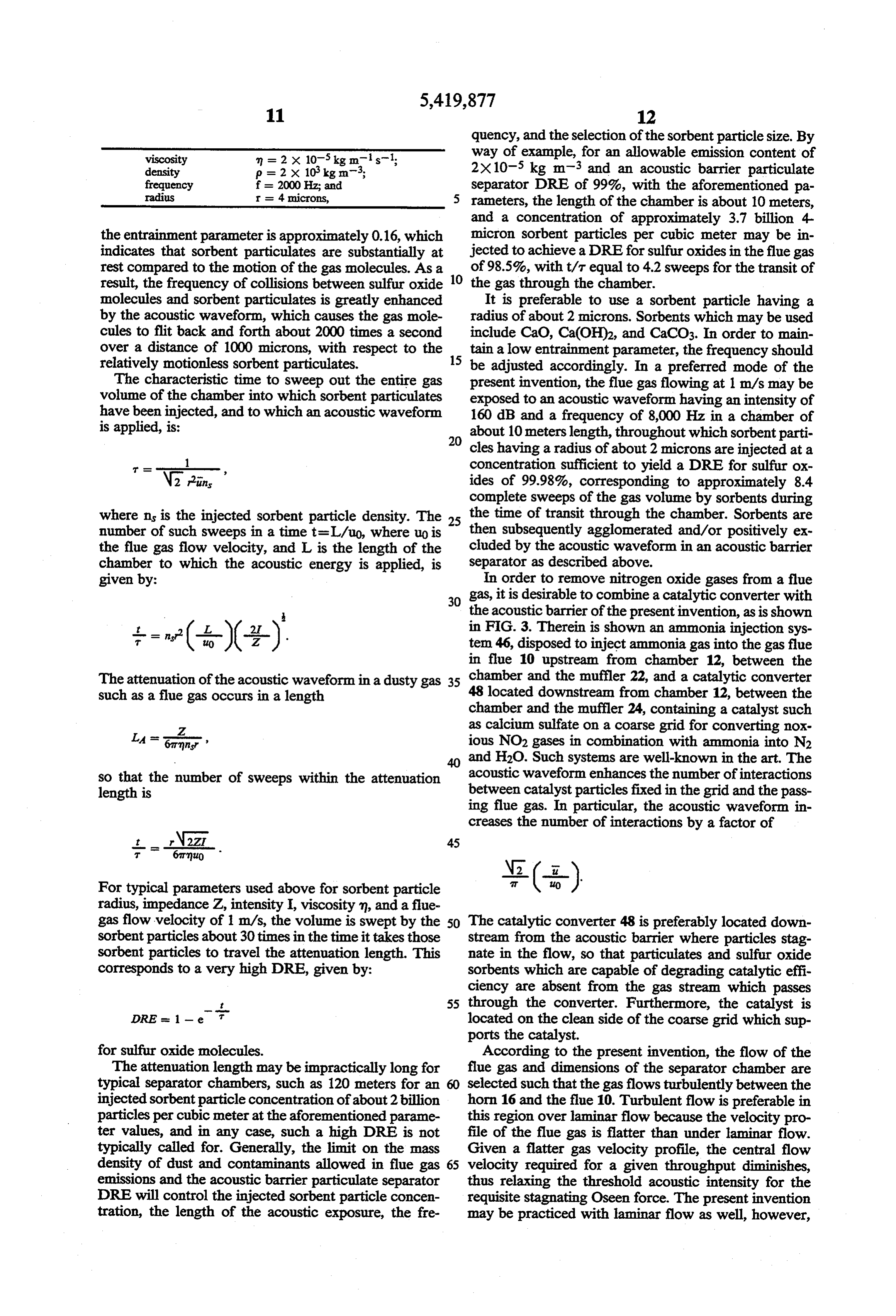
Page 12
quency, and the selection of the sorbent particle size. By viscosity n = 2 x 10⁵ kg mist; way of example, for an allowable emission content of density p = 2 x 10⁸ kg m3; 2x10 kg m3 and an acoustic barrier particulate frequency f = 2000 Hz; and separator DRE of 99%, with the aforementioned pa radius r = 4 microns, rameters, the length of the chamber is about 10 meters, and a concentration of approximately 3.7 billion 4 the entrainment parameter is approximately 0.16, which micron sorbent particles per cubic meter may be in indicates that sorbent particulates are substantially at jected to achieve a DRE for sulfur oxides in the flue gas rest compared to the motion of the gas molecules. As a of 98.5%, with twit equal to 4.2 sweeps for the transit of result, the frequency of collisions between sulfur oxide 10 the gas through the chamber. molecules and sorbent particulates is greatly enhanced It is preferable to use a sorbent particle having a by the acoustic waveform, which causes the gas mole radius of about 2 microns. Sorbents which may be used cules to flit back and forth about 2000 times a second include CaO, Ca(OH)2, and CaCO3. In order to main over a distance of 1000 microns, with respect to the 15 tain a low entrainment parameter, the frequency should relatively motionless sorbent particulates. be adjusted accordingly. In a preferred mode of the The characteristic time to sweep out the entire gas present invention, the flue gas flowing at 1 m/s may be volume of the chamber into which sorbent particulates exposed to an acoustic waveform having an intensity of have been injected, and to which an acoustic waveform 160 dB and a frequency of 8,000 Hz in a chamber of is applied, is:
20 about 10 meters length, throughout which sorbent parti cles having a radius of about 2 microns are injected at a 1 concentration sufficient to yield a DRE for sulfur ox
\22in, ides of 99.98%, corresponding to approximately 8.4 complete sweeps of the gas volume by sorbents during where ns is the injected sorbent particle density. The 25 the time of transit through the chamber. Sorbents are number of such sweeps in a time t=L/uo, where u0 is then subsequently agglomerated and/or positively ex the flue gas flow velocity, and L is the length of the cluded by the acoustic waveform in an acoustic barrier chamber to which the acoustic energy is applied, is separator as described above.
given by: In order to remove nitrogen oxide gases from a flue 30 gas, it is desirable to combine a catalytic converter with the acoustic barrier of the present invention, as is shown +--(4)(3-) in FIG. 3. Therein is shown an ammonia injection sys tem 46, disposed to inject ammonia gas into the gas flue in flue 10 upstream from chamber 12, between the
The attenuation of the acoustic waveform in a dusty gas 35 chamber and the muffler 22, and a catalytic converter such as a flue gas occurs in a length 48 located downstream from chamber 12, between the chamber and the muffler 24, containing a catalyst such
Z as calcium sulfate on a coarse grid for converting nox LA = 6 s ious NO2 gases in combination with ammonia into N2 and H2O. Such systems are well-known in the art. The so that the number of sweeps within the attenuation acoustic waveform enhances the number of interactions length is between catalyst particles fixed in the grid and the pass ing flue gas. In particular, the acoustic waveform in creases the number of interactions by a factor of
For typical parameters used above for sorbent particle radius, impedance Z, intensity I, viscosity m, and a flue
gas flow velocity of 1 m/s, the volume is swept by the 50 The catalytic converter 48 is preferably located down sorbent particles about 30 times in the time it takes those stream from the acoustic barrier where particles stag sorbent particles to travel the attenuation length. This nate in the flow, so that particulates and sulfur oxide corresponds to a very high DRE, given by: sorbents which are capable of degrading catalytic effi ciency are absent from the gas stream which passes --- 55 through the converter. Furthermore, the catalyst is
located on the clean side of the coarse grid which sup ports the catalyst.
for sulfur oxide molecules. According to the present invention, the flow of the The attenuation length may be impractically long for flue gas and dimensions of the separator chamber are typical separator chambers, such as 120 meters for an selected such that the gas flows turbulently between the injected sorbent particle concentration of about 2 billion horn 16 and the flue 10. Turbulent flow is preferable in particles per cubic meter at the aforementioned parame this region over laminar flow because the velocity pro ter values, and in any case, such a high DRE is not file of the flue gas is flatter than under laminar flow. typically called for. Generally, the limit on the mass Given a flatter gas velocity profile, the central flow density of dust and contaminants allowed in flue gas 65 velocity required for a given throughput diminishes, emissions and the acoustic barrier particulate separator thus relaxing the threshold acoustic intensity for the DRE will control the injected sorbent particle concen requisite stagnating Oseen force. The present invention tration, the length of the acoustic exposure, the fre may be practiced with laminar flow as well, however,
Page 13
the acoustic intensity required to positively exclude a deflected from the flue gas flow by the acoustic Oseen given diameter particulate will be relatively greater force during transit through the chamber 70. These because of the greater gas flow velocity at the axial deflected solids are collected in a solids collection center of chamber 12. Laminar flow is distinguished in hopper 76 located laterally from the axis of flue gas that the flow velocity at the axial center of a tube is flow. As needed for maintaining proper operation of the about twice the average flow velocity. invention, a level sensor may be placed on the inside As mentioned above, absorption of the acoustic wall of the chamber 70, preferably close to the surface power to prevent resonance and standing wave phe of the solids that are collected in the solids collection nomenon may be obtained by maintaining a predeter hopper.
mined level of solids in the solids collection hopper 34. O Chamber 70 and conduits 68 and 74 may be insulated The level of solids in the hopper may be monitored by as described above for the embodiment shown in FIG. a number of well-known techniques in the arts including 1 to reduce the overall noise given off by the entire proximity detectors using acoustic frequency emissions, apparatus. Similarly, mufflers 78 and 80 may be located which measure the time of reflection of an incident upstream and downstream, respectively, from the signal to gauge the distance to the top of the solids in the 15 chamber 70, to further reduce the noise which may hopper. escape from the apparatus.
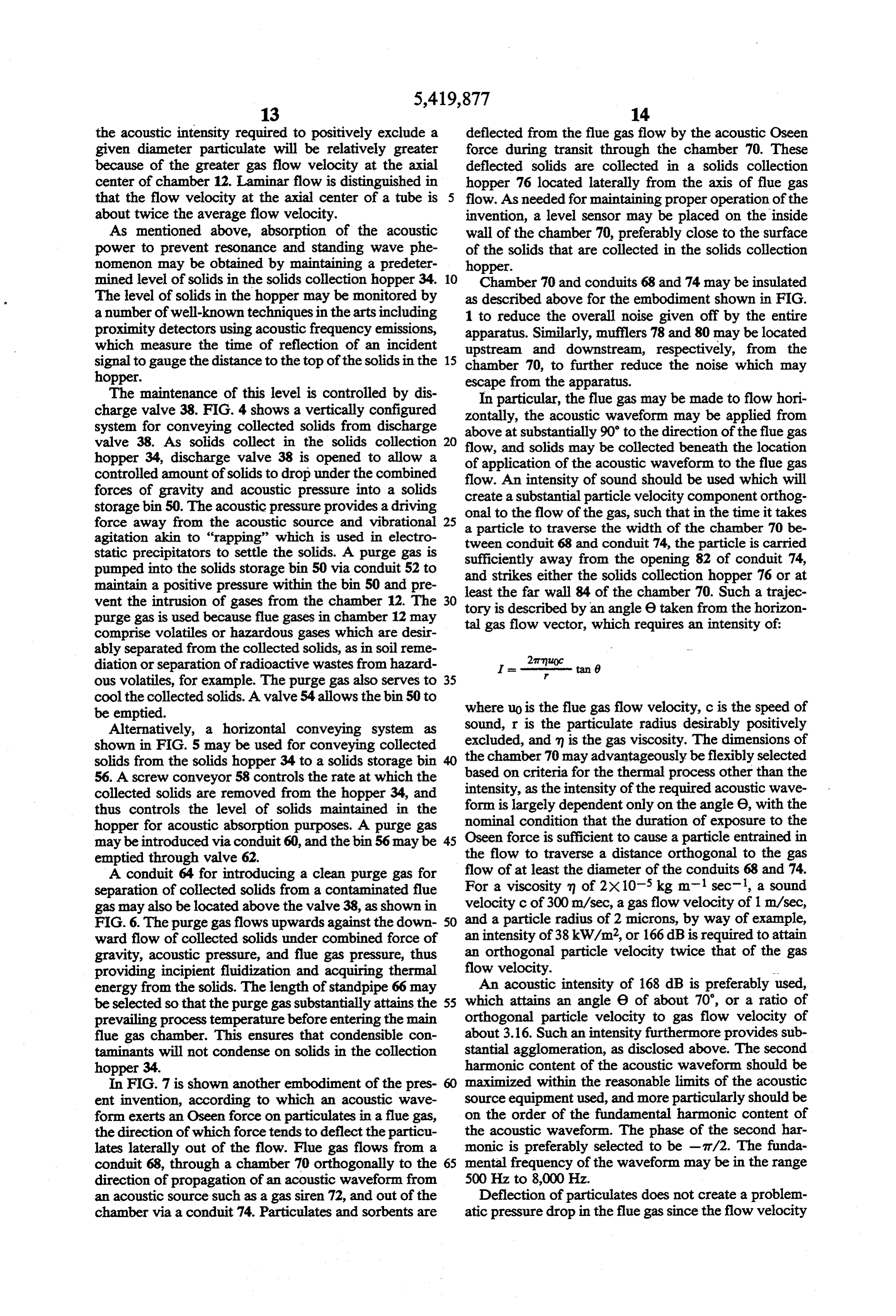
The maintenance of this level is controlled by dis In particular, the flue gas may be made to flow hori charge valve 38. FIG. 4 shows a vertically configured zontally, the acoustic waveform may be applied from system for conveying collected solids from discharge above at substantially 90 to the direction of the flue gas valve 38. As solids collect in the solids collection 20 flow, and solids may be collected beneath the location hopper 34, discharge valve 38 is opened to allow a of application of the acoustic waveform to the flue gas controlled amount of solids to drop under the combined forces of gravity and acoustic pressure into a solids flow. An intensity of sound should be used which will storage bin 50. The acoustic pressure provides a driving onal toathe create substantial particle velocity component orthog flow of the gas, such that in the time it takes force away from the acoustic source and vibrational 25 a particle to traverse the width of the chamber 70 be agitation akin to “rapping” which is used in electro tween conduit 68 and conduit 74, the particle is carried static precipitators to settle the solids. A purge gas is sufficiently away from the opening 82 of conduit 74, pumped into the solids storage bin 50 via conduit 52 to and strikes either the solids collection hopper 76 or at maintain a positive pressure within the bin 50 and pre least the far wall 84 of the chamber 70. Such a trajec vent the intrusion of gases from the chamber 12. The 30 tory is described by an angle e taken from the horizon purge gas is used because flue gases in chamber 12 may tal gas flow vector, which requires an intensity of comprise volatiles or hazardous gases which are desir ably separated from the collected solids, as in soil reme diation or separation of radioactive wastes from hazard 27truoc tan 8 ous volatiles, for example. The purge gas also serves to 35 cool the collected solids. A valve 54 allows the bin 50 to be emptied. where uo is the flue gas flow velocity, c is the speed of Alternatively, a horizontal conveying system as sound, r is the particulate radius desirably positively shown in FIG. 5 may be used for conveying collected excluded, and m is the gas viscosity. The dimensions of solids from the solids hopper 34 to a solids storage bin the chamber 70 may advantageously be flexibly selected 56. A screw conveyor 58 controls the rate at which the based on criteria for the thermal process other than the collected solids are removed from the hopper 34, and intensity, as the intensity of the required acoustic wave thus controls the level of solids maintained in the form is largely dependent only on the angle 6, with the hopper for acoustic absorption purposes. A purge gas nominal condition that the duration of exposure to the may be introduced via conduit 60, and the bin 56 may be 45 Oseen force is sufficient to cause a particle entrained in emptied through valve 62. the flow to traverse a distance orthogonal to the gas A conduit 64 for introducing a clean purge gas for flow of at least the diameter of the conduits 68 and 74. separation of collected solids from a contaminated flue For a viscosity m of 2x10⁻⁵ kg m-1 sec, a sound gas may also be located above the valve 38, as shown in velocity c of 300 m/sec, a gas flow velocity of 1 m/sec, FIG. 6. The purge gas flows upwards against the down 50 and a particle radius of 2 microns, by way of example, ward flow of collected solids under combined force of an intensity of 38kW/m2, or 166 dB is required to attain gravity, acoustic pressure, and flue gas pressure, thus an orthogonal particle velocity twice that of the gas providing incipient fluidization and acquiring thermal flow velocity.
energy from the solids. The length of standpipe 66 may An acoustic intensity of 168 dB is preferably used, be selected so that the purge gas substantially attains the 55 which attains an angle 6 of about 70', or a ratio of prevailing process temperature before entering the main orthogonal particle velocity to gas flow velocity of flue gas chamber. This ensures that condensible con about 3.16. Such an intensity furthermore provides sub taminants will not condense on solids in the collection stantial agglomeration, as disclosed above. The second hopper 34. harmonic content of the acoustic waveform should be In FIG. 7 is shown another embodiment of the pres maximized within the reasonable limits of the acoustic ent invention, according to which an acoustic wave source equipment used, and more particularly should be form exerts an Oseen force on particulates in a flue gas, on the order of the fundamental harmonic content of the direction of which force tends to deflect the particu the acoustic waveform. The phase of the second har lates laterally out of the flow. Flue gas flows from a monic is preferably selected to be -nt/2. The funda conduit 68, through a chamber 70 orthogonally to the 65 mental frequency of the waveform may be in the range direction of propagation of an acoustic waveform from 500 Hz to 8,000 Hz.
an acoustic source such as a gas siren 72, and out of the Deflection of particulates does not create a problem chamber via a conduit 74. Particulates and sorbents are atic pressure drop in the flue gas since the flow velocity
Page 14
along the original flue gas velocity vector remains un having a diameter of 40 micrometers or less were en changed. The flue gas itself is only negligibly deflected trained in the gas and were carried upward through the by the tangential motion of the particulates because gas inlet, through the separator tube, and out through generally the total gas mass is much greater than the the gas exit port. The peak gas flow speed was 8 cm/s total particulate mass. in the gas inlet and exit tubes, and was estimated to be 4 Further according to the embodiment shown in FIG. cm/s in the separator tube (twice the equilibrium flow 7, a sulfur oxide sorbent particle injection means 86 is value). The gas was allowed to flow through the tube located upstream from the chamber 70, between the for 2 minutes. The flow was then stopped and the filter chamber and muffler 78. Such an injection means may was removed and weighed the next day (after be any one of various means widely known in the art for O rehumidification) to determine the mass of the particu injecting such sorbents into a flue gas for sweeping up lates.
sulfur oxide gases. The sorbent injection means 86 is The test was repeated with the sound turned on, i.e., preferably located about ten meters upstream from the in the presence of an acoustic wave. With the sound entrance to the chamber 70. turned on, the dust was observed to stagnate in a cloud Acoustic energy is provided to the sorbent particles 15 just beyond the gas inlet tube. Much thinner clouds in the flue gas along a 10-meter distance between the were also evident spaced a half wave apart along the point of injection and the entrance to the chamber 70 by separator tube, indicating a standing wave component the acoustic source 72, some of the energy of which due to acoustic reflection at the gas inlet. The dust travels out of chamber 70 and into conduit 68. The clouds dissipated over about 1 minute as particles col chamber 70 and conduits 68 and 74 are designed accord 20 lected on the wall of the separator tube and fell into the ing to well-known requirements in the field of acoustic collection hopper.
waveguides to provide for this transmission of some of Three types of dust were tested as described above: the acoustic energy into the conduit 68. In particular, graphite, diatomaceous earth, and bone char. After with an acoustic source intensity of 168 dB, it is desir conducting the test, the gas inlet end was removed from able to allow acoustic energy of about 160 dB intensity 25 the separator tube and a movable calibrated micro to propagate into conduit 68 for the purpose of enhanc phone probe was inserted through 5 inches of low den ing the effectiveness of the injected sorbents. sity foam to determine the sound intensity in the separa The radius of the injected sorbent particles is prefera tor tube under conditions of minimal reflection. The bly in the range of about 1 micron to about 5 microns, microphone generated a voltage signal proportional to and more particularly is about 2 microns. Sorbents 30 acoustic pressure. The pressure signal was found to be which may be used include CaO, Ca(OH)2, and CaCO3. constant to within 10 percent as the axial position of the The fundamental frequency of the acoustic waveform is microphone probe was varied.
then preferably about 8,000 Hz. The percentage of the particulate mass remaining in A catalytic converter 88 as known in the art may be the flow as a function of sound intensity was deter employed in conduit 74 downstream from chamber 70, mined. At low sound intensity, the particulate mass for between the chamber and muffler 80, for removal of the graphite dust was larger than that for nosound be nitrogen oxides from the flue gas. The converter com cause the fluid bed was more agitated when the sound prises a coarse grid which supports a catalyst such as was on. At a high sound intensity, the removal effi calcium sulfate. Ammonia is injected into the flue gas at ciency varied from 94% for graphite dust to 99% for ammonia injection means 90, located between the bone char dust, with the removal efficiency increasing chamber 70 and muffler 78. with the sound intensity.
Gas siren 72 is powered by a process gas flowing in The filters were examined by microscope to deter via conduit 92 and flowing out via conduit 94. The siren mine a cutoff diameter, defined as that diameter where is effectively isolated from the high temperatures of the 99% of the particulates retained on the filter are smaller separation chamber 70 by an isolating seal 96, which is 45 than the cutoff diameter. The cutoff diameter was found acoustically transparent. A sheet of felted, woven and to vary from about 40 micrometers at low sound inten sintered stainless steel may be used as a seal. sity to 4.5-8 micrometers at the highest intensity used. Example 1 The data obtained reasonably follow the stagnation condition that the diameter cannot exceed a critical
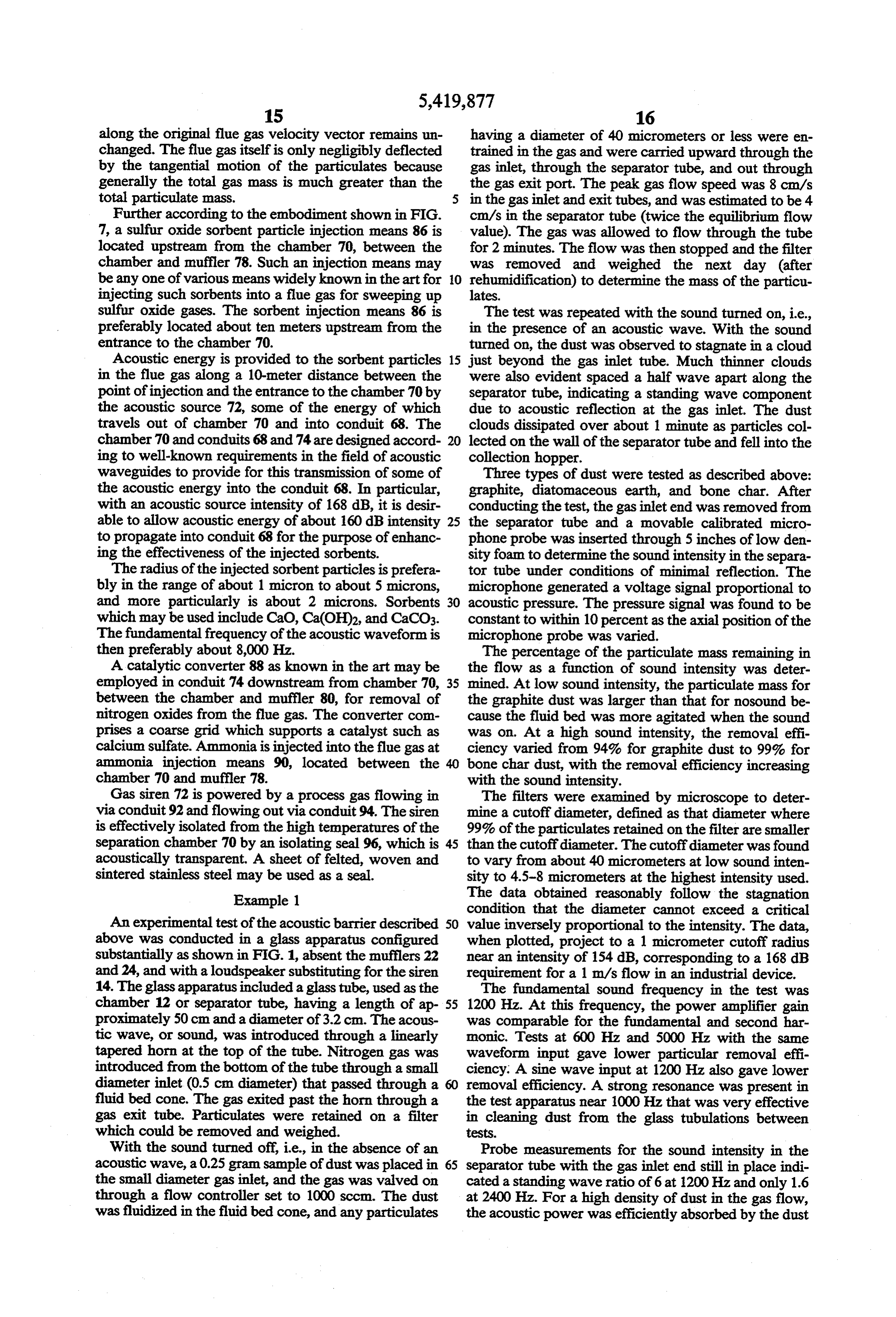
An experimental test of the acoustic barrier described 50 value inversely proportional to the intensity. The data, above was conducted in a glass apparatus configured when plotted, project to a 1 micrometer cutoff radius substantially as shown in FIG. 1, absent the mufflers 22 near an intensity of 154 dB, corresponding to a 168 dB and 24, and with a loudspeaker substituting for the siren requirement for a 1 m/s flow in an industrial device. 14. The glass apparatus included a glass tube, used as the The fundamental sound frequency in the test was chamber 12 or separator tube, having a length of ap 55 1200 Hz. At this frequency, the power amplifier gain proximately 50 cm and a diameter of 3.2 cm. The acous was comparable for the fundamental and second har tic wave, or sound, was introduced through a linearly monic. Tests at 600 Hz and 5000 Hz with the same tapered horn at the top of the tube. Nitrogen gas was waveform input gave lower particular removal effi introduced from the bottom of the tube through a small ciency. A sine wave input at 1200 Hz also gave lower diameter inlet (0.5 cm diameter) that passed through a removal efficiency. A strong resonance was present in fluid bed cone. The gas exited past the horn through a the test apparatus near 1000 Hz that was very effective gas exit tube. Particulates were retained on a filter in cleaning dust from the glass tubulations between which could be removed and weighed. tests.
With the sound turned off, i.e., in the absence of an Probe measurements for the sound intensity in the acoustic wave, a 0.25 gram sample of dust was placed in separator tube with the gas inlet end still in place indi the small diameter gas inlet, and the gas was valved on cated a standing wave ratio of 6 at 1200 Hz and only 1.6 through a flow controller set to 1000 sccm. The dust at 2400 Hz. For a high density of dust in the gas flow, was fluidized in the fluid bed cone, and any particulates the acoustic power was efficiently absorbed by the dust
Page 15
itself such that the reflected power was low. However, b. Place an o-ring in lower glass face, add o-ring on for low dust density the test apparatus acted like a reso top, raise to position, and clamp. Tighten screw nant cavity (driven somewhat off resonance in the tests) on clamp.
for the fundamental. The second harmonic continued to c. Add acoustic absorber pipe to outlet tube end. be essentially a unidirectional traveling wave that was 5 5. Conduct Test largely absorbed in the termination. Such a configura a. With gas inlet tubing disconnected from separa tion is calculated to retain a large net Oseen force. tor, clear tubing of dust at max flow and then set flow rate, record flow rate.
Example 2 b. Close gas shutoff valve to stop flow.
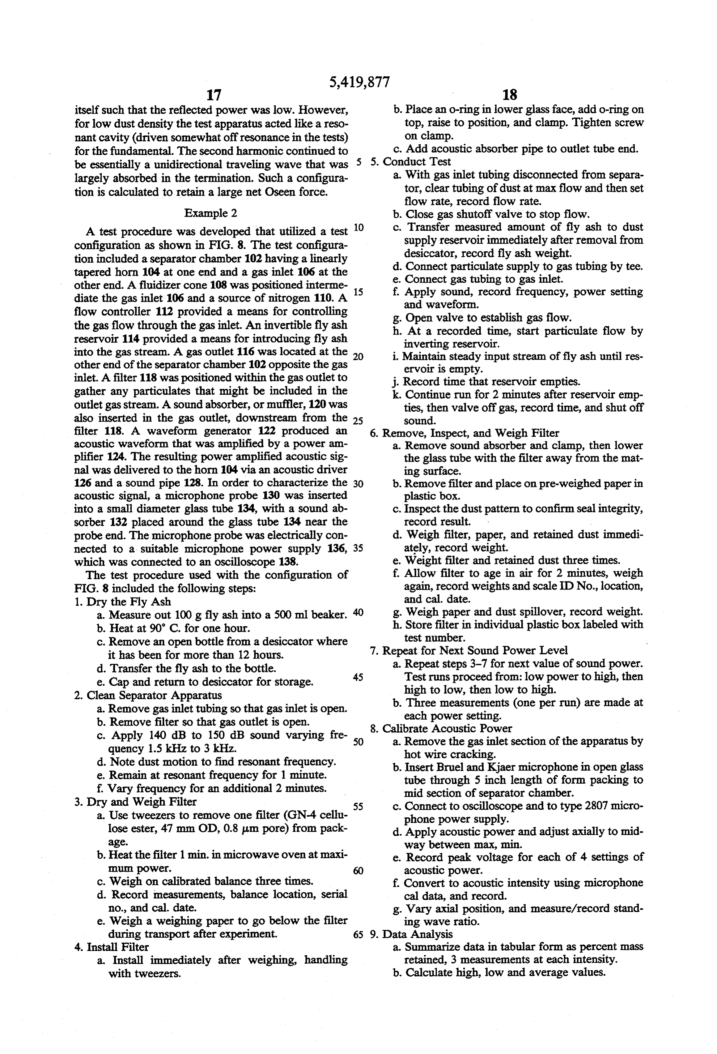
A test procedure was developed that utilized a test c. Transfer measured amount of fly ash to dust configuration as shown in FIG. 8. The test configura supply reservoir immediately after removal from tion included a separator chamber 102 having a linearly desiccator, record fly ash weight. tapered horn 104 at one end and a gas inlet 106 at the d. Connect particulate supply to gas tubing by tee. other end. A fluidizer cone 108 was positioned interme e. Connect gas tubing to gas inlet. diate the gas inlet 106 and a source of nitrogen 110. A 1S f. Apply sound, record frequency, power setting and waveform.
flow controller 112 provided a means for controlling g. Open valve to establish gas flow. the gas flow through the gas inlet. An invertible fly ash h. At a recorded time, start particulate flow by reservoir 114 provided a means for introducing fly ash inverting reservoir.
into the gas stream. A gas outlet 116 was located at the 20 i. Maintain steady input stream of fly ash until res other end of the separator chamber 102 opposite the gas ervoir is empty.
inlet. A filter 118 was positioned within the gas outlet to j. Record time that reservoir empties. gather any particulates that might be included in the k. Continue run for 2 minutes after reservoir emp outlet gas stream. A sound absorber, or muffler, 120 was ties, then valve off gas, record time, and shut off also inserted in the gas outlet, downstream from the 25 sound.
filter 118. A waveform generator 122 produced an 6. Remove, Inspect, and Weigh Filter acoustic waveform that was amplified by a power am a. Remove sound absorber and clamp, then lower plifier 124. The resulting power amplified acoustic sig the glass tube with the filter away from the mat nal was delivered to the horn 104 via an acoustic driver ing surface.
126 and a sound pipe 128. In order to characterize the 30 b. Remove filter and place on pre-weighed paper in acoustic signal, a microphone probe 130 was inserted plastic box.
into a small diameter glass tube 134, with a sound ab c. Inspect the dust pattern to confirm seal integrity, sorber 132 placed around the glass tube 134 near the record result.
probe end. The microphone probe was electrically con d. Weigh filter, paper, and retained dust immedi nected to a suitable microphone power supply 136, 35 ately, record weight. which was connected to an oscilloscope 138. e. Weight filter and retained dust three times. The test procedure used with the configuration of f. Allow filter to age in air for 2 minutes, weigh FIG. 8 included the following steps: again, record weights and scale ID No., location, 1. Dry the Fly Ash and cal. date.
a. Measure out 100 g fly ash into a 500 ml beaker. 40 g. Weigh paper and dust spillover, record weight. b. Heat at 90° C. for one hour. h. Store filter in individual plastic box labeled with c. Remove an open bottle from a desiccator where test number.
it has been for more than 12 hours. 7. Repeat for Next Sound Power Level d. Transfer the fly ash to the bottle. a. Repeat steps 3-7 for next value of sound power. e. Cap and return to desiccator for storage. 45 Test runs proceed from: low power to high, then 2. Clean Separator Apparatus high to low, then low to high. a. Remove gas inlet tubing so that gas inlet is open. b. Three measurements (one per run) are made at b. Remove filter so that gas outlet is open. each power setting.
8. Calibrate Acoustic Power c. Apply 140 dB to 150 dB sound varying fre 50 a. Remove the gas inlet section of the apparatus by quency 1.5 kHz to 3 kHz. hot wire cracking.
d. Note dust motion to find resonant frequency. b. Insert Bruel and Kjaer microphone in open glass e. Remain at resonant frequency for 1 minute. tube through 5 inch length of form packing to f. Vary frequency for an additional 2 minutes. mid section of separator chamber. 3. Dry and Weigh Filter 55 c. Connect to oscilloscope and to type 2807 micro a. Use tweezers to remove one filter (GN-4 cellu phone power supply.
lose ester, 47 mm OD, 0.8 um pore) from pack d. Apply acoustic power and adjust axially to mid age. way between max, min.
b. Heat the filter 1 min. in microwave oven at maxi e. Record peak voltage for each of 4 settings of mum power. acoustic power.
c. Weigh on calibrated balance three times. f. Convert to acoustic intensity using microphone d. Record measurements, balance location, serial cal data, and record.
no., and cal. date. g. Vary axial position, and measure/record stand e. Weigh a weighing paper to go below the filter ing wave ratio.
during transport after experiment. 65 9. Data Analysis 4. Install Filter a. Summarize data in tabular form as percent mass a. Install immediately after weighing, handling retained, 3 measurements at each intensity. with tweezers. b. Calculate high, low and average values.
Page 16
c. Plot average value of mass retained versus inten collection means for collecting particulates forced sity. from the gas flow in said separator chamber by the d. Indicate confidence level by bar connecting high Oseen force.
and low values. 2. An apparatus according to claim 1, wherein said Using the above procedure, several separation tests 5 acoustic waveform generating means comprises means were performed. The acoustic measurements (acoustic for generating the acoustic waveform so that it has a power calibration) were performed prior to beginning fundamental frequency and a second harmonic that is the separator tests. Also, prior to the separation tests, phase shifted about -T/2 radians with respect to said the filter was dried by inserting it in a microwave oven 10 fundamental frequency.
for 1 minute, and its weight was noted with time expo 3. An apparatus according to claim 2, wherein said sure to room air on a rainy day. The filter weight was acoustic waveform generating means includes means stable to within 0.2 mg over 20 minutes and did not for generating the acoustic waveform so that approxi trend upward. Each separation test required between 1 mately the same amount of power is included in the hour and 1.5 hour to complete, including filter prepara 15 second harmonic as is included in the fundamental fre tion and final weighing and recording. During the sepa quency.
ration test, it required about 10 minutes to empty the fly 4. An apparatus according to claim 2, wherein said ash hopper which contained 1 gram of fly ash. Each acoustic waveform generating means includes means filter with retained fly ash was weighed within 5 min for selecting the frequency of the fundamental fre utes after the gas flow (1.1 liters min) was stopped. The 20 quency to be within the range of audible frequencies. fly ash used complied with ASTM C 618, and was certi 5. An apparatus according to claim 4, wherein said fied by the supplier. The nitrogen used was 99.98% acoustic waveform generating means generates the fun damental frequency to be within the frequency range pure and was also certified by the supplier. The flow from 500 Hz to 8,000 Hz.
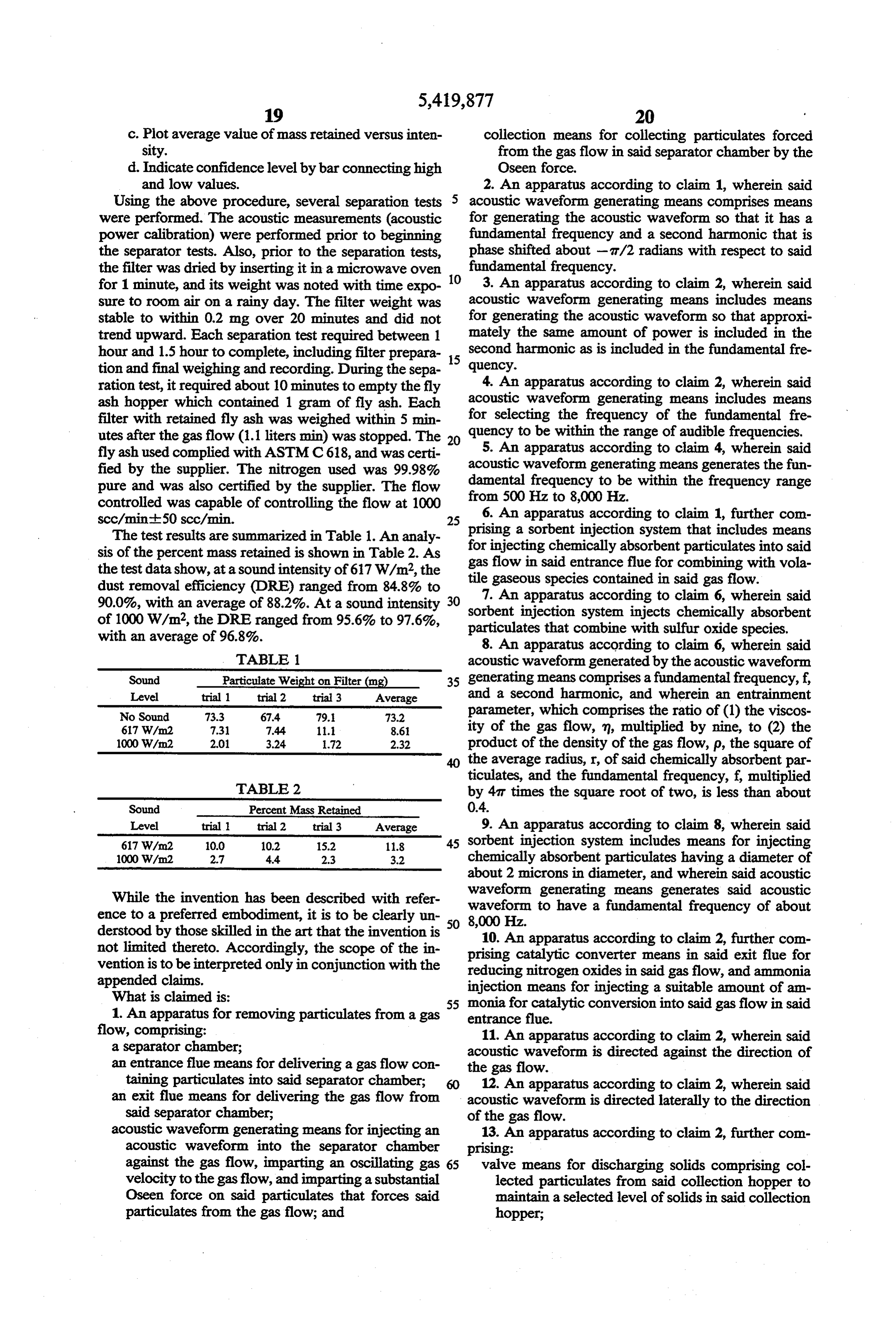
controlled was capable of controlling the flow at 1000 scc/mini--50 scc/min. 25 6. An apparatus according to claim 1, further com The test results are summarized in Table 1. An analy prising for a sorbent injection system that includes means injecting chemically absorbent particulates into said sis of the percent mass retained is shown in Table 2. As gas flow in said entrance flue for combining with vola the test data show, at a sound intensity of 617W/m2, the tile gaseous species contained in said gas flow. dust removal efficiency (DRE) ranged from 84.8% to 7. An apparatus according to claim 6, wherein said 90.0%, with an average of 88.2%. At a sound intensity 30 sorbent injection system injects chemically absorbent of 1000 W/m2, the DRE ranged from 95.6% to 97.6%, particulates that combine with sulfur oxide species. with an average of 96.8%. 8. An apparatus according to claim 6, wherein said TABLE 1. acoustic waveform generated by the acoustic waveform Sound Particulate Weight on Filter (ng) 35 generating means comprises a fundamental frequency, f, Level trial 1 trial 2 trial 3 Average and a second harmonic, and wherein an entrainment No Sound 73.3 67.4 79. 73.2 parameter, which comprises the ratio of (1) the viscos 617 W/m2 7.31 7.44 11. 8.61 ity of the gas flow, m, multiplied by nine, to (2) the 1000 W/m2 2.01 3.24 1.72 2.32 product of the density of the gas flow, p, the square of the average radius, r, of said chemically absorbent par ticulates, and the fundamental frequency, f, multiplied
TABLE 2 by 4t times the square root of two, is less than about Sound Percent Mass Retained 0.4.
Level trial trial 2 trial 3 Average 9. An apparatus according to claim 8, wherein said 617 WAn2 10.0 10.2 15.2 1.8 45 sorbent injection system includes means for injecting 1000 W/m2 2.7 4.4 2.3 3.2 chemically absorbent particulates having a diameter of about 2 microns in diameter, and wherein said acoustic
While the invention has been described with refer waveform generating means generates said acoustic ence to a preferred embodiment, it is to be clearly un SO 8,000 Hz. to have a fundamental frequency of about waveform derstood by those skilled in the art that the invention is 10. An apparatus according to claim 2, further com not limited thereto. Accordingly, the scope of the in prising vention is to be interpreted only in conjunction with the reducingcatalytic nitrogen converter means in said exit flue for oxides in said gas flow, and ammonia appended claims. injection means for injecting a suitable amount of am What is claimed is: 55 monia for catalytic conversion into said gas flow in said 1. An apparatus for removing particulates from a gas entrance flue.
flow, comprising: 11. An apparatus according to claim 2, wherein said a separator chamber; acoustic waveform is directed against the direction of an entrance flue means for delivering a gas flow con the gas flow.
taining particulates into said separator chamber; 12. An apparatus according to claim 2, wherein said an exit flue means for delivering the gas flow from acoustic waveform is directed laterally to the direction said separator chamber; of the gas flow.
acoustic waveform generating means for injecting an 13. An apparatus according to claim 2, further com acoustic waveform into the separator chamber prising:
against the gas flow, imparting an oscillating gas valve means for discharging solids comprising col velocity to the gas flow, and imparting a substantial lected particulates from said collection hopper to Oseen force on said particulates that forces said maintain a selected level of solids in said collection particulates from the gas flow; and hopper;
Page 17
bin means for receiving discharged solids via said p." apparatus according to claim 13, further com valve; and a horizontal conduit between said valve and said bin; and means for providing a sufficient positive air pressure 5 conveyor screw means for conveying along said hori in said bin to prevent infiltration into said bin via zontal conduit to said bin solids discharged by said valve.
said valve by gas from the gas flow. st
Provenance
- Collection
- Cited prior art
- Original PDF
- patentimages.storage.googleapis.com →
- Filed
- 1993-09-17
- Pages
- 17
- Method
- pdftotext (the PDF's own text layer) + pdftoppm 300dpi page scans
- Source
- Google Patents bibliographic record
- Granted
- 1995-05-30
- Inventors
- Robert R. Goforth; Tihiro Ohkawa; General Atomics Corp
- Transcribed from
- patentimages.storage.googleapis.com →