patent · US20120258410A1
Oxy-hydrogen fuel integration and control system
11 October 2012
Page 1 — bibliographic record
(19) United States (12) Patent Application Publication (10) Pub. No.: US 2012/0258410 A1
ROBINSON (43) Pub. Date: Oct. 11, 2012 (54) OXY-HYDROGEN FUEL INTEGRATION AND Publication Classification CONTROL SYSTEM (51) Int. Cl.
(76) Inventor: MARK MACDONOUGH F23N 5/00 (2006.01) ROBINSON, Kingston, MA (US) (52) U.S. Cl. ................................ 431/29: 431/72: 431/18 (21) Appl. No.: 13/438,140 (57) ABSTRACT An oxy-hydrogen generator control system may include an (22) Filed: Apr. 3, 2012 oxy-hydrogen generator for fuel production on demand. A controller may determine if ignition is present in a burner
Related U.S. Application Data assembly prior to generating the oxy-hydrogen fuel and pro viding it to the burner assembly. The controller may also (60) Provisional application No. 61/472,978, filed on Apr. purge system lines of any residual oxy-hydrogen fuel when 7, 2011. heating is no longer needed.
SIGNAL CONFIRMSPRIMARYIGNITION y
THERMOSTAT
OXYHYDROGEN y
OUTPUTS ACTIVATE CONVENTIONAL BURNER
DELIVERAIRTO
PURGE
CLOSES RELAY
CALL FOR
WALWETO
DEWEROXY.
HYDROGEN
TOBURN 135
S AIR WNEA LOWPRESSURE FACLITY - - TANK 130 TANK AIRSUPPLY POWER - N - HHO GAS AIR (<100psi)
Page 2
Drawing sheet — no readable text.
Page 3
Drawing sheet — no readable text.
Page 4
Patent Application Publication Oct. 11, 2012 Sheet 3 of 4 US 2012/O25841.0 A1
TOBURNER
WALVE POSITION 1
DURING BURN
130 DELIVERS GAS
HHO 131 133 137 PLAN AIR
GAS
WALWE POSITION2
130 DURINGPURGE
DELIVERSPURGED AIR
PLAN
HHO
WALVE POSITION3
SYSTEMNOTACTIVE
130 PURGED DEVERY
CIRCUITREMAINS
PASSES OTHERWAY
HHO 131 133 137 PLAN
GAS
Page 5
Patent Application Publication Oct. 11, 2012 Sheet 4 of 4 US 2012/0258410 A1 OXYHYDROGENSYSTEMCONTROLISTURNEDON 405 7400
YES OXYHYDROGENSYSTEMCONTROL NO
DETERMINES FELECTRICALSUPPLY
SPRESENT
OXYHYDROGENSYSTEM -42) OXY-HYDROGENSYSTEMCONTROLCONTINVESTOLOOKING FORELECTRICAL I-45 ACTIVE AND READY SUPPLYUNTITISPRESENT ORTHESYSTEMIS MANUALLY SHUTDOWN OXYHYDROGENSYSTEMCONTROL DETECTS ACALL FROM THE FURNACE OR HOT WATER HEATERTHERMOSTAT 425 OXYHYDROGENSYSTEMCONTROL OXYHYDROGENSYSTEMCONTROLFALSTODETECT PRIMARY SYSTEM DETECTSPRIMARY IGNITION ACTIVATES ANALARM, CONTINVESTOMONITORUNTILPRIMARY SYSTEMIGNITION? SYSTEMIGNITION DETECTED ORSYSTEMIS MANUALLY SHUTDOWN YES 430 436 OXY-HYDROGENSYSTEMCONTROLACTIVATESOXYHYDROGENSUPPLYUNTPOWERAND ACTIVATES 440 THEOXYHYDROGENFUEDEVERY VALVE POSITIONINGIT TO ALLOWTHE FLOY OFOXYHYDROGEN TOEEDELIVERED TO THE DISPENSINGNOZZLEMOUNTED WITHINTHEBURNER ASSEMBLY
OXYHYDROGENSYSTEMCONTROLRECEIVES THESIGNALFROM THEAPPROPRIATETHERMOSTAT THAT 445
HEATORHOTWATERARENOLONGER NEEDED
OXY-HYDROGENSYSTEMCONTROL DEACTIVATES THEOXYHYDROGEN SUPPLYUNTAND MOVES THE POSITION 450 OF THE FUEDELVERYFLOWVALVEFROMFUELPOSITIONTO COMPRESSEDARPOSITION FOR ASETPERIOD OF TIVEADEQUATE TO PURGETHEREMAINING OXYHYDROGENTIMEEXPRES VALVECLOSES
OXYHYDROGENSYSTEMCONTROLREMAINSACTIVEWATING FORSUBSEQUENT CALL FROM THETHERMOSTAT AND ARESUMPTION OF THECYCLEORUNTILTHESYSTEMISSHUTDOWNMANUALLY MANUAL
SHUTDOWN
FIG. 4
Page 6
US 2012/025841.0 A1 Oct. 11, 2012
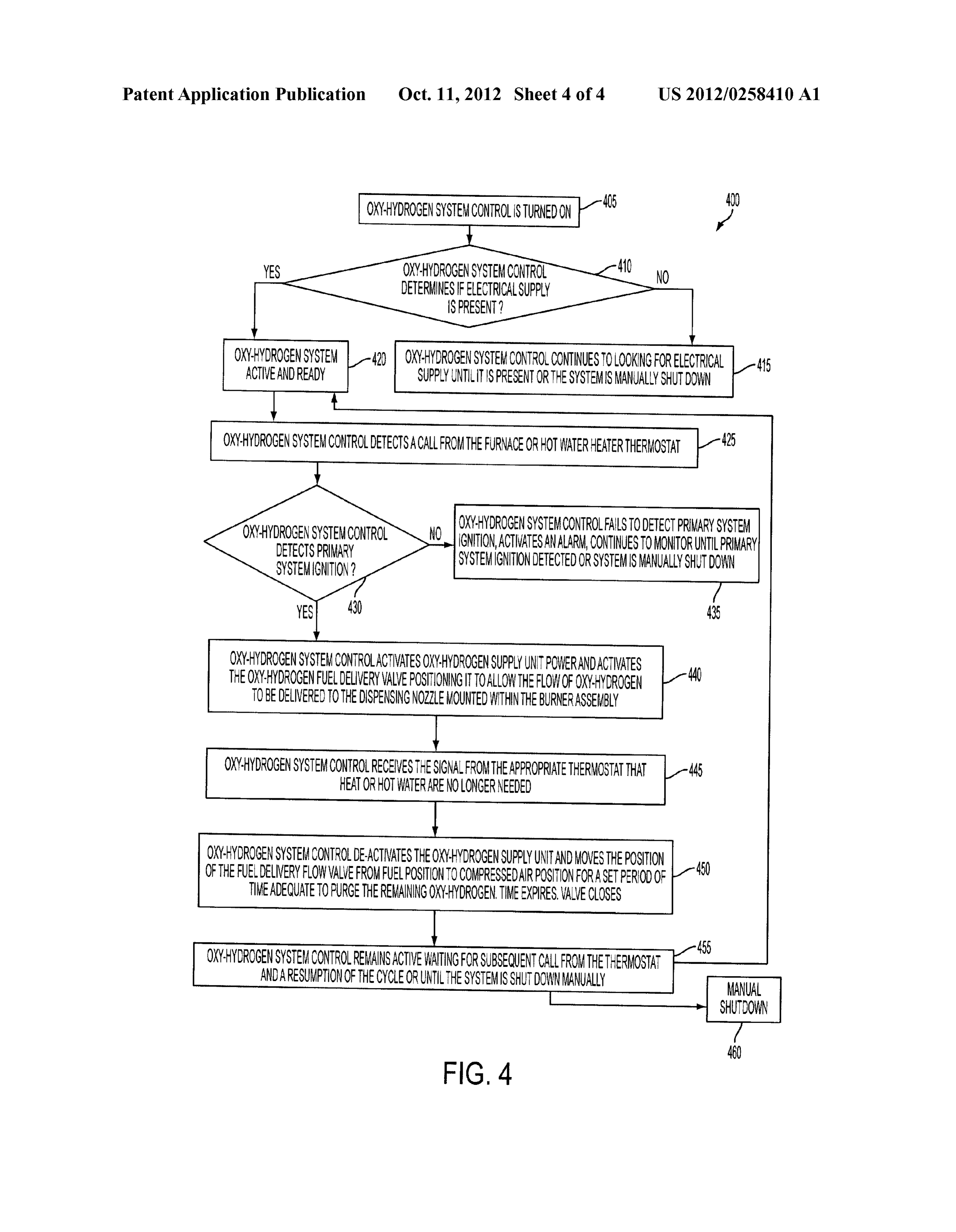
OXY-HYDROGEN FUEL INTEGRATION AND 0012 FIG. 4 is a flowchart illustrating a series of steps CONTROL SYSTEM according to an exemplary embodiment of the present inven tion.
CROSS-REFERENCE TO RELATED
APPLICATION DETAILED DESCRIPTION OF THE INVENTION 0001. This application claims benefit under 35 U.S.C. 0013 The following detailed description is of the best S119(e) of U.S. Provisional Application having Ser. No. currently contemplated modes of carrying out exemplary 61/472,978 filed Apr. 7, 2011, which is hereby incorporated embodiments of the invention. The description is not to be by reference herein in its entirety. taken in a limiting sense, but is made merely for the purpose of illustrating the general principles of the invention, since the
BACKGROUND OF THE INVENTION scope of the invention is best defined by the appended claims. 0002 The present invention generally relates to fuel gen 0014 Broadly, an embodiment of the present invention generally provides an oxy-hydrogen generation integration eration systems, and more particularly to an oxy-hydrogen and control system. In one aspect, exemplary embodiments of fuel generation system. the present invention may be useful in, for example, residen 0003 Heating and hot water systems where people reside tial or commercial environments. Aspects of the present or work that rely on petroleum fuel can be cost prohibitive and invention may supply an oxy-hydrogen fuel as an alternative waste fuel due to inefficient combustion. Inefficient combus heating source to petroleum based systems. Aspects of the tion also produces higher levels of pollution. present invention may generate oxy-hydrogen fuel on 0004 Additionally, traditional storage of hydrogen alone demand rather than storing a static Supply of fuel. By contrast involved keeping it as a liquid in a pressurized tank which can with heating systems that rely on petroleum fuel, oxy-hydro present dangerous conditions. For example, in storage tanks, gen on demand generation uses water as the only fuel stored there exists an ever present danger that the storage tank may which presents no risk of combustion under any condition. explode. Moreover, another aspect of the present invention provides a 0005. As can be seen, there is a need for a safe fuel source control system for enabling generation of oxy-hydrogen fuel that can be generated on demand. Additionally, there is a need under safety conditions.
for a fuel generator system that can be controlled to operate 0015 Referring now to FIG. 1, a schematic of an oxy under safe conditions.
hydrogen generation control system 100 (also referred to as
SUMMARY OF THE INVENTION
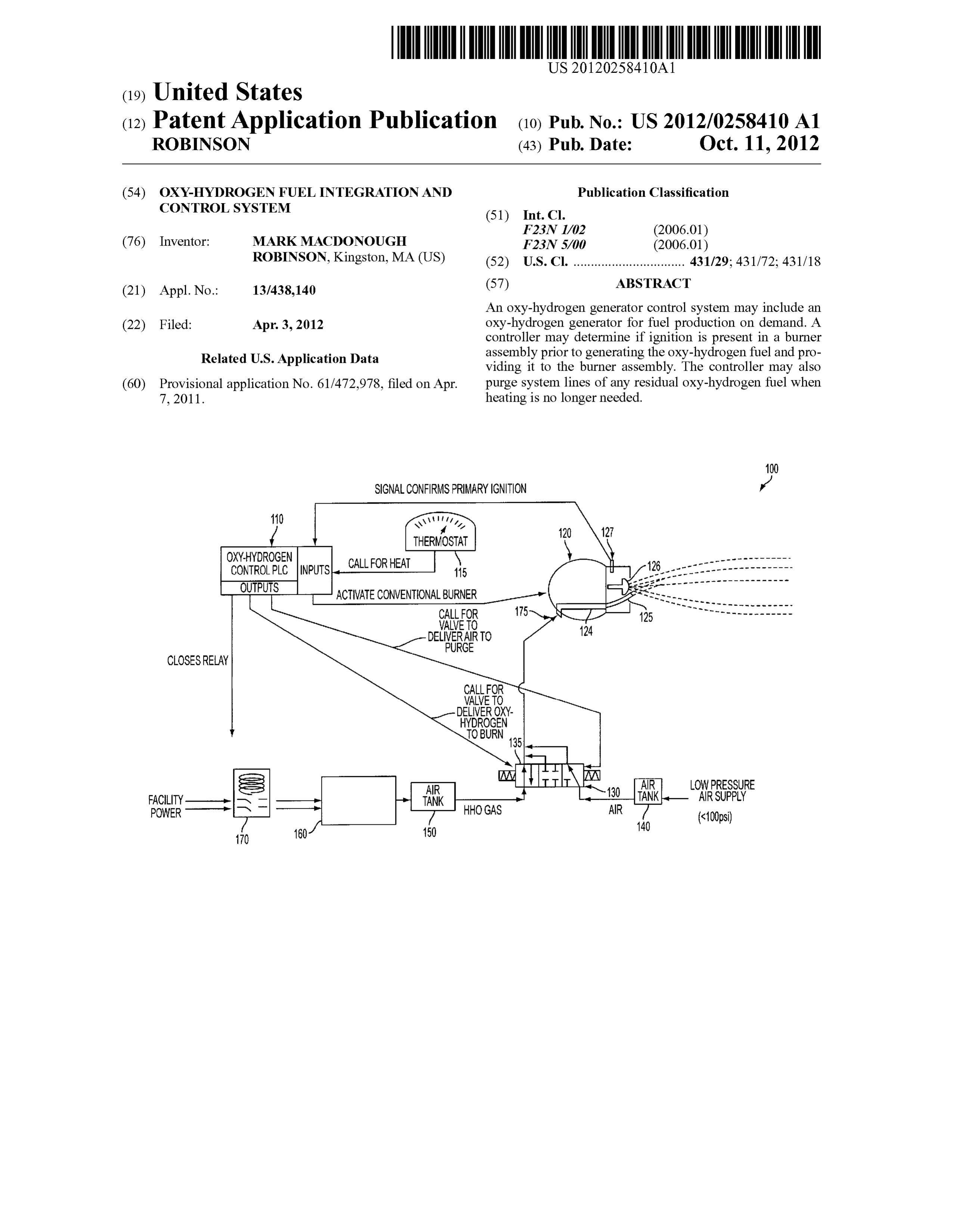
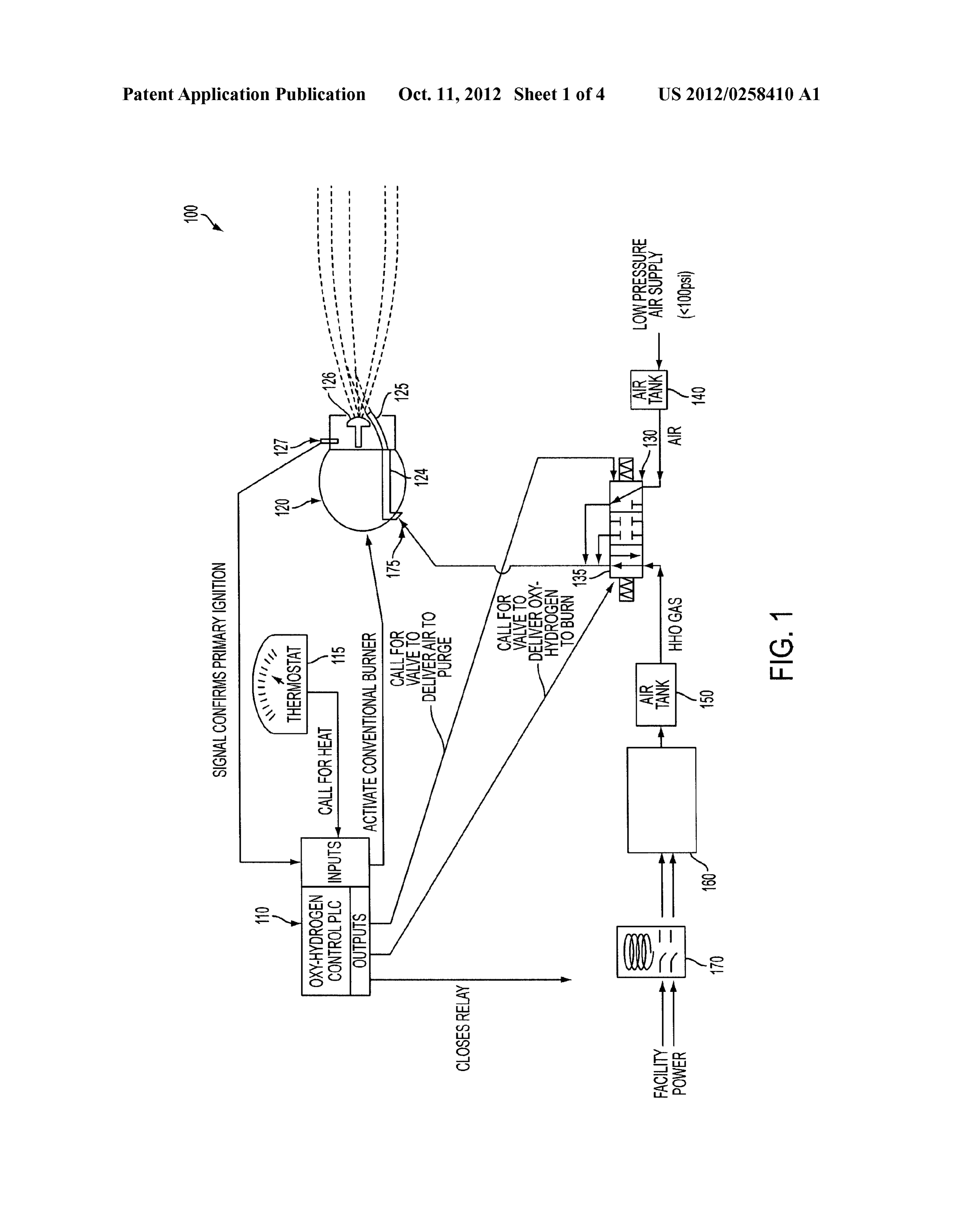
the “system 100') is shown in accordance with exemplary embodiments of the present invention. The system 100 may 0006. In one aspect of the present invention, an oxy-hy include a controller 110, a burner assembly 120, and an oxy drogen generator control system comprises a burner assem hydrogen generator 160. The system 100 may also include a bly; an oxy-hydrogen generator coupled to the burner assem manifold 130 between the burner assembly 120 and the oxy bly; a valve coupled between the oxy-hydrogen generator and hydrogen generator 160. A flashback arrestor 150 may be the burner assembly; and a controller coupled to the valve and positioned between the manifold 130 and the oxy-hydrogen the burner assembly, the controller configured to: detect a generator 160. A non-combustible air source 140 may be heat distribution source signal to initiate oxy-hydrogen fuel coupled to the manifold 130.
generation, detect a burner assembly signal that an ignition 0016. In one aspect, the controller 110 may be configured Source is enabled, and provide a valve opening signal to the to control the production of oxy-hydrogen and the feed of valve to allow oxy-hydrogen fuel into the burner assembly. oxy-hydrogen to the burner assembly 120 safely. For 0007. In another aspect of the present invention, an oxy example, the controller 110 may be a programmable device, hydrogen generator control system comprises a burner for example, a microprocessor including non-volatile assembly; an oxy-hydrogen generator coupled to the burner memory incorporating instructions to operate elements of the assembly; a valve coupled between the oxy-hydrogen gen system 100. It will be understood that lines emanating from erator and the burner assembly; and a controller coupled to the controller 100 to other elements in the system 100 may be the valve and the burner assembly, the controller configured electrical connections carrying signals. to: detect a signal from a heat distribution Source to initiate 0017. In one exemplary embodiment, the controller 110 oxy-hydrogen fuel generation, detect a signal from the burner may be coupled to a thermostat 115. The thermostat 115 may assembly that an ignition source is enabled, and provide a be programmable to indicate to the controller 110 a threshold signal to the valve to allow oxy-hydrogen fuel into the burner temperature that is needed at a heat distribution source (not assembly. shown), for example, a furnace or a hot water system. A 0008. These and other features, aspects and advantages of switch 170, for example, a relay, may be coupled between the the present invention will become better understood with controller 110 and the oxy-hydrogen generator 160. When the reference to the following drawings, description and claims. thermostat is below the threshold temperature, the controller 110 may be configured to close the switch 170 so that a power
BRIEF DESCRIPTION OF THE DRAWINGS Supply (not shown) is delivered to the oxy-hydrogen genera tor 160. In one exemplary embodiment, the oxy-hydrogen 0009 FIG. 1 is schematic diagram of an oxy-hydrogen generator 160 may be an electrolysis system carrying a water generation control system according to an exemplary reserve that is converted into oxy-hydrogen fuel on demand embodiment of the present invention; rather than stored.
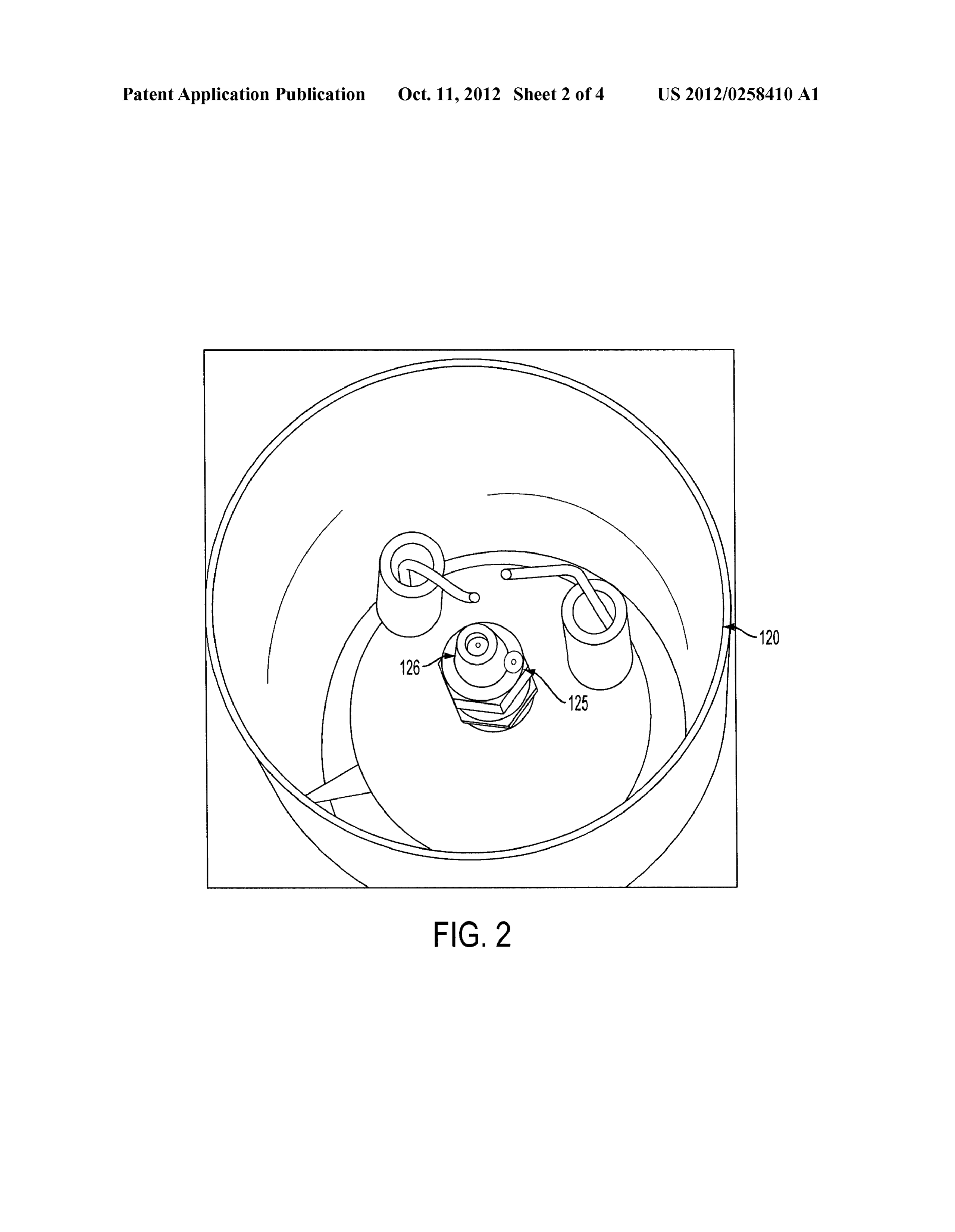
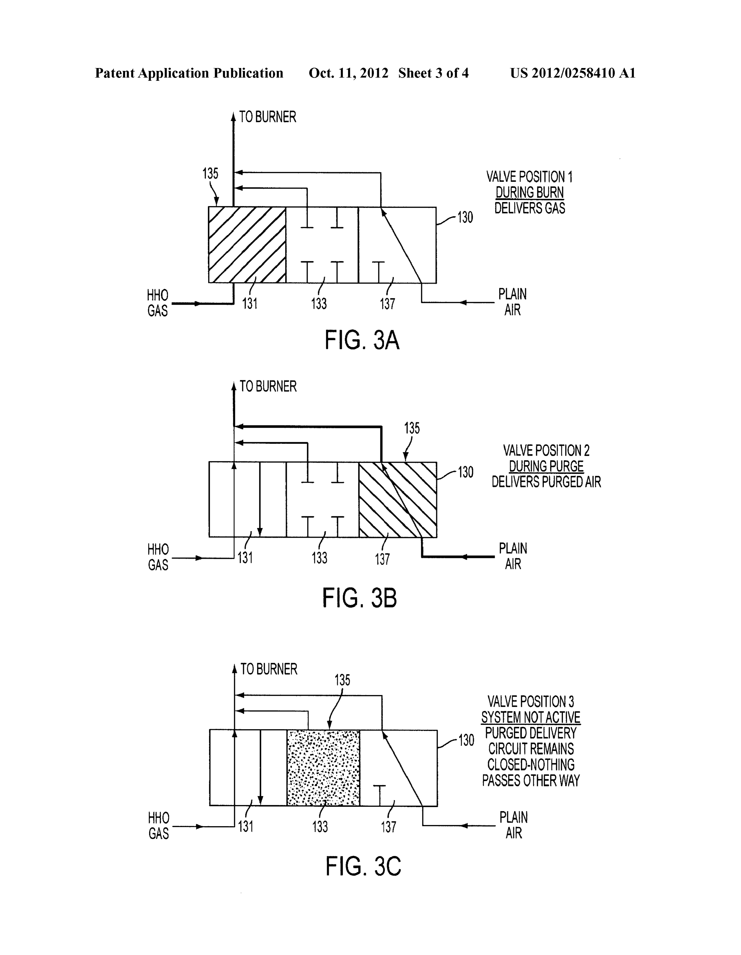
0010 FIG. 2 is top plan view of a burner assembly for use (0018. Referring now to FIGS. 1 and 2, the system 100 and in the system of FIG. 1; an enlarged view of the burner assembly 120 is shown in 0011 FIGS. 3A-3C are schematic illustrations of a valve accordance with an exemplary embodiment of the present and valve positions during use in the system of FIG. 1; and invention. The burner assembly 120 may include a micro
Page 7
US 2012/025841.0 A1 Oct. 11, 2012
nozzle 125 and a primary fuel ignition nozzle 126. The micro 110 may receive an indication from the thermostat 115 that nozzle 125 may be proximate the primary fuel ignition nozzle the temperature threshold is reached and additional heating is 126 so that fuel being expelled by the micro-nozzle 125 may not needed. In step 450, the controller 110 may open the be ignited by a lit primary fuel ignition nozzle 126. The switch 170 and cut off power to the oxy-hydrogen generator micro-nozzle is utilized in this low pressure application to 160. The controller 110 may also move the valve 135 into the insure a positive exit pressure is maintained prohibiting any air purge delivery mode for a predetermined time, for potential burn back and to insure the gas travels to the center example 10 seconds and the valve 135 may then enter into the of the primary flame pattern insuring even heat distribution. closed mode. In step 455, the controller 110 may wait until the The controller 110 may be connected to the burner assembly thermostat 115 indicates the need for more heating or the system may then proceed into a shutdown in step 460.
120 so that the ignition nozzle 126 may be enabled and ignited 0021. It should be understood, of course, that the forego by igniters 123 by commands from the controller 110. An ing relates to exemplary embodiments of the invention and ignition thermal sensor 127 may be proximate the ignition that modifications may be made without departing from the nozzle 126. The controller 110 may be connected to the spirit and scope of the invention as set forth in the following ignition thermal sensor 127 to determine based on feedback claims.
from the thermal sensor 127 that verifies the ignition nozzle What is claimed is:
126 is indeed lit. 1. An oxy-hydrogen generator control system, comprising: 0019 Referring now to FIGS. 1 and 3A-3C, the system a burner assembly;
100 and various configurations of the manifold 130 are shown an oxy-hydrogen generator coupled to the burner assem in accordance with exemplary embodiments of the present bly:
invention. The controller 110 may also be connected to the a valve coupled between the oxy-hydrogen generator and manifold 130. The manifold 130 may include an electrically the burner assembly; and activated pneumatic three position valve 135 allowing fluid to a controller coupled to the valve and the burner assembly, flow from the manifold 130 through conduit 175 to the micro the controller configured to: nozzle 125. The conduit 175 may include an internal volume detect a heat distribution source signal to initiate oxy insufficient to support combustibility within the line, for hydrogen fuel generation, example, less than 200 mL. The controller 110 may control detect a burner assembly signal that an ignition Source is the position of the valve 135 between an oxy-hydrogen gas enabled, and delivery mode, an air purge delivery mode, and a closed provide a valve opening signal to the valve to allow oxy mode. FIG. 3A shows the oxy-hydrogen gas delivery mode hydrogen fuel into the burner assembly. where the valve 135 oxy-hydrogen gas to flow through sec 2. The oxy-hydrogen generator control system of claim 1 tion 131 to the burner assembly 120. FIG. 3B shows the air wherein the oxy-hydrogen generator is an electrolysis sys purge delivery mode where the valve 135 closes the section tem.
131. Thus, the flow of oxy-hydrogen gas through to the burner 3. The oxy-hydrogen generator control system of claim 2 assembly 125 is cutoff. Meanwhile, section 137 is opened, wherein the controller is configured to detect if electrical allowing non-combustible air from an air source 140 to flow power is available to the electrolysis system. into the conduit 175 and purging any residual oxy-hydrogen 4. The oxy-hydrogen generator control system of claim 1 gas from the line to the burner assembly 120. The air source wherein the valve includes an oxy-hydrogen gas delivery may be under low pressure, for example, less than 100 psi. mode, an air purge delivery mode, and a closed mode. FIG. 3C shows the closed mode where sections 131, 133, and 5. The oxy-hydrogen generator control system of claim 4 137 may all be partitioned from access to conduit 175. wherein the controller is also configured to, during the purge 0020 Referring now to FIGS. 1 and 4, use of the system delivery mode, purge a conduit leading to the burner assem 100 through a series of steps of a method 400 are illustrated bly from the valve prior to closing the valve into the closed according to another exemplary embodiment of the present mode.
invention. In step 405, the system controller 110 may be 6. The oxy-hydrogen generator control system of claim 1 activated. In step 410, the controller 110 may determine is wherein the burner assembly includes a micro-nozzle power is available. If not, in step 415, the controller 110 may coupled to the valve and the ignition source is disposed proxi wait for power to be available or the system 100 may enter a mate the micro-nozzle.
shutdown mode. If power is available, in step 420 the system 7. An oxy-hydrogen generator control system, comprising: 100 enters a ready state. In step 425, the controller 110 may an oxy-hydrogen micro-nozzle burner; receive temperature level request from the thermostat 115 an oxy-hydrogen electrolysis generator coupled to the activating the controller 110 to supply heat to a heat distribu micro-nozzle burner, tion source. In step 430, the controller 110 activates the pri a water source coupled to the electrolysis generator; mary burner unit 120 control which initiates primary fuel a conduit between the electrolysis generator and the micro ignition at the primary fuel ignition noZZle 126 and may check nozzle burner, the conduit having an internal Volume of if the ignition nozzle 126 is indeed lit. If the controller 110 less than 200 ml; and determines that the ignition nozzle 126 is not lit, then the a controller coupled to the valve and the burner assembly, controller 110 may activate an alarm until the nozzle 126 is lit the controller configured to: or the system 100 is shutdown. If the nozzle 126 is indeed lit, detect a signal that an ignition Source proximate the then in step 440, the controller 110 may provide power to the micro-nozzle burner is enabled, and oxy-hydrogen generator 160 to produce oxy-hydrogen gas allow oxy-hydrogen fuel from the electrolysis generator and move the valve 135 into oxy-hydrogen gas delivery mode into the micro-nozzle burner. where the oxy-hydrogen fuel may be combusted in the burner 8. The oxy-hydrogen generator control system of claim 7 assembly 120 and the resultant heat is delivered to the heat further comprising a switch coupled between the controller distribution source (not shown). In step 445, the controller and the electrolysis generator, wherein the controller is con
Page 8
US 2012/025841.0 A1 Oct. 11, 2012
figured to close the switch and allow power to the electrolysis 10. The oxy-hydrogen generator control system of claim 8 generator for producing oxy-hydrogen fuel. further comprising a thermostat coupled to the controller 9. The oxy-hydrogen generator control system of claim 8 wherein the controller is configured to open the switch when wherein the controller is configured to release a non-combus- a threshold temperature is detected on the thermostat. tible air Supply into the conduit purging oxy-hydrogen fuel from the conduit. ck

Provenance
- Collection
- Patents citing this work
- Pages
- 8
- Method
- pdftotext (the PDF's own text layer) + pdftoppm 300dpi page scans
- Patent office record
- patents.google.com →
- Source
- Google Patents citing-documents table
- Assignee
- Mark Macdonough Robinson
- Inventors
- Mark Macdonough Robinson
- Published
- 2012-10-11
- Transcribed from
- patentimages.storage.googleapis.com →