patent · US3298785
Burner and method of use
17 January 1967
Page 1
Drawing sheet — no readable text.
Page 2
United States Patent Office 3,298,785 Patented Jan. 17, 1967
inner passageway and separate outer passageways about 3,298,785 the inner passageway. Each of said passageways has an
BURNER AND METHOD OF USE inlet end and an outlet end and said inlet ends are dis Friedrich Reul, Windecken, Hanau, Germany, assignor to posed adjacent each other and the outlet ends are disposed Heraeas Quarzschmelze G.m.b.H., Rohrstrasse, Ger many, a corporation of Germany adjacent each other. Means are provided for introduc Filed Dec. 21, 1962, Ser. No. 246,572 ing fuel into the inlet end of the inner-passageway, and Claims priority, application Germany, Jan. 13, 1962, means are provided for placing material for facilitating H 44,610 burning (hydrogen and oxygen in the case of the Dr.
8 Claims. " (Cl. 23-230) Wickbold burner) of the fuel into the inlet end of the
This invention relates to burners and finds particular Further, according to the invention, the fuel and one of application in the case of burners used for analysis of the materials for facilitating combustion are admixed at material in liquid or gas form. The apparatus and pro the discharge of the fuel supply passageway (the inner cedure of the invention is particularly well suited for the passageway) and additional material for facilitating com. burning and analysis of organic liquids and gases. 5 bustion of the fuel is released from the outer passageway Apparatus is known for the determination of sulfur, at a point spaced from the discharge end of the two inner halogen, and boron content of organic substances by passageways. : } quantitative combustion of the substances. An example i. In accordance with the invention, the burner com of such apparatus is the Dr. Wickbold burner. prises four concentrically disposed pipes providing a first These analysis burners are suction burners and com 20 passageway through the innermost pipe, a second pas prise four concentrically disposed pipes whereby an inner sageway as as annulus about the first passageway, a third passageway and three annular passageways are provided. passageway as an annulus about said second passageway, The inner passageway is referred to herein as the first and a fourth passageway as an annulus about the third passageway and the innermost annular passageway is passageway. Fuel is to be introduced into the first referred to as the second passageway, the next annular passageway and material for facilitating burning of the passageway as the third passageway, and the outermost fuel is introduced through the remaining three passage annular passageway as the fourth passageway. In the ways. ' - known apparatus the oxygen necessary for combustion is The invention particularly contemplates an apparatus passed through the inner or first passageway; the sub comprising four concentrically disposed pipes, as just stance to be analyzed is passed through the second pas described, and wherein the first, second, and third pas sageway; a combustible gas, usually hydrogen, is passed sageways terminate short of the fourth or outermost pas through the third passageway; and excess oxygen is passed sageway. Such construction is provided by terminating through the fourth passageway. The oxygen supply the two inner pipes short, of the two outer pipes. The Supports combustion, and the hydrogen supply provides two inner pipes can terminate in the same plane which a flame to assure burning of the substance to be analyzed 35 is perpendicular to the axis of the burner and the two (herein referred to as the fuel). In the known apparatus, outer pipes can terminate in the same plane, also per the exit ends of the pipes terminate in a common plane pendicular to the axis of the burner. * perpendicular to the axis of the pipes. The invention provides the burning procedure wherein These known burners have the disadvantage that the at least part of the material for facilitating combustion substance to be analyzed burns at the mouth of the 4. is conveyed by its delivery pipe to a locus of release respective supply pipes, and solids are deposited at the - spaced from the outlet end of the pipe through which exit ends of the burner. As a consequence, the pipes, the fuel is conveyed, whereby the material for facilitating particularly the pipes defining the passageway for the combustion is admixed with the fuel at the locus spaced substance to be analyzed or the fuel, may become com from the outlet end of the fuel delivery pipe, and burning pletely closed so that the device is inoperative, or may 45 of the fuel occurs at a locus spaced from the outlet end become partially closed so that errors occur in the of the fuel delivery pipe. Thus, the fuel is burned at a analysis. Moreover, in the known burners, the exit end locus removed from the outlet end of its delivery pipe, of the burner is heated to the extent that the substance and combustion does not start at the said outlet end as is analyzed, if a liquid, is vaporized within the passageway the case for prior art burners. Further, if the fuel is in through which it travels, and, depending on the substance 50 liquid form, conversion of the fuel into a gas does not being analyzed, solids are deposited in the pipe by reason take place in the fuel delivery pipe, but rather occurs of this evaporation in the pipe. This tends to clog the after discharge of the fuel from the outlet end of its pipe. pipe and may occasion errors in analysis. In the four pipe burners of the prior art, oxygen is The thermally stressed parts of the known burners are passed through the inner pipe, the fuel is passed through made up of quartz. 55 the first annular passageway, hydrogen through the second It is a principal object of the invention to provide a annular passageway and oxygen through the third annular burner which is free of the mentioned disadvantages of passageway. According to the invention, fuel is passed the known burners. through the inner pipe, oxygen can be passed through According to the invention, a burner construction is the first and second annular passageways, and hydrogen provided which is characterized in that the burning of the 60 can be passed through the third annular passageway. fuel (substance to be analyzed) occurs at a locus spaced This preferred procedure offers the advantage that the from the discharge end of the passageway through which fuel is well shielded from the hydrogen which diffuses the fuel passes. This prevents the deposit of solids due readily. The hydrogen provides the igniting flame, main to burning at the discharge of the fuel supply passageway, tains the combustion, and assures complete combustion . and further reduces the extent to which the discharge end 65 of the fuel. Since the hydrogen is released at a point of the fuel supply passageway is heated, so that, in the spaced from the outlet end of the fuel supply pipe, burn case of liquids, evaporation does not occur or does not ing tends to occur at a locus spaced from the outlet end occur to as great an extent, as in the case of burners of the fuel supply pipe and adjacent the outlet end of the wherein the burning takes place at the discharge of the hydrogen supply pipe. Further, this arrangement pro fuel Supply passageway. 70 vides a cooling effect at the burner end of the apparatus. According to the invention, a burner comprises a In another preferred embodiment of the invention, the plurality of concentrically disposed pipes providing an cross-sectional flow area of the passageways adjacent the
Page 3
outlet ends thereof, decreases in the direction of the out - particular embodiments thereof, various modifications let ends. This provides an increase in flow velocity as the will occur to those skilled in the art whose desire it is de fuel and materials for facilitating approach the outlet ends sired to secure by these letters passed all such modifica of their respective pipes. Another preferred embodiment, tions as are within the scope of the appended claims. is with respect to the relative cross-sectional flow area of 5 What is claimed is:
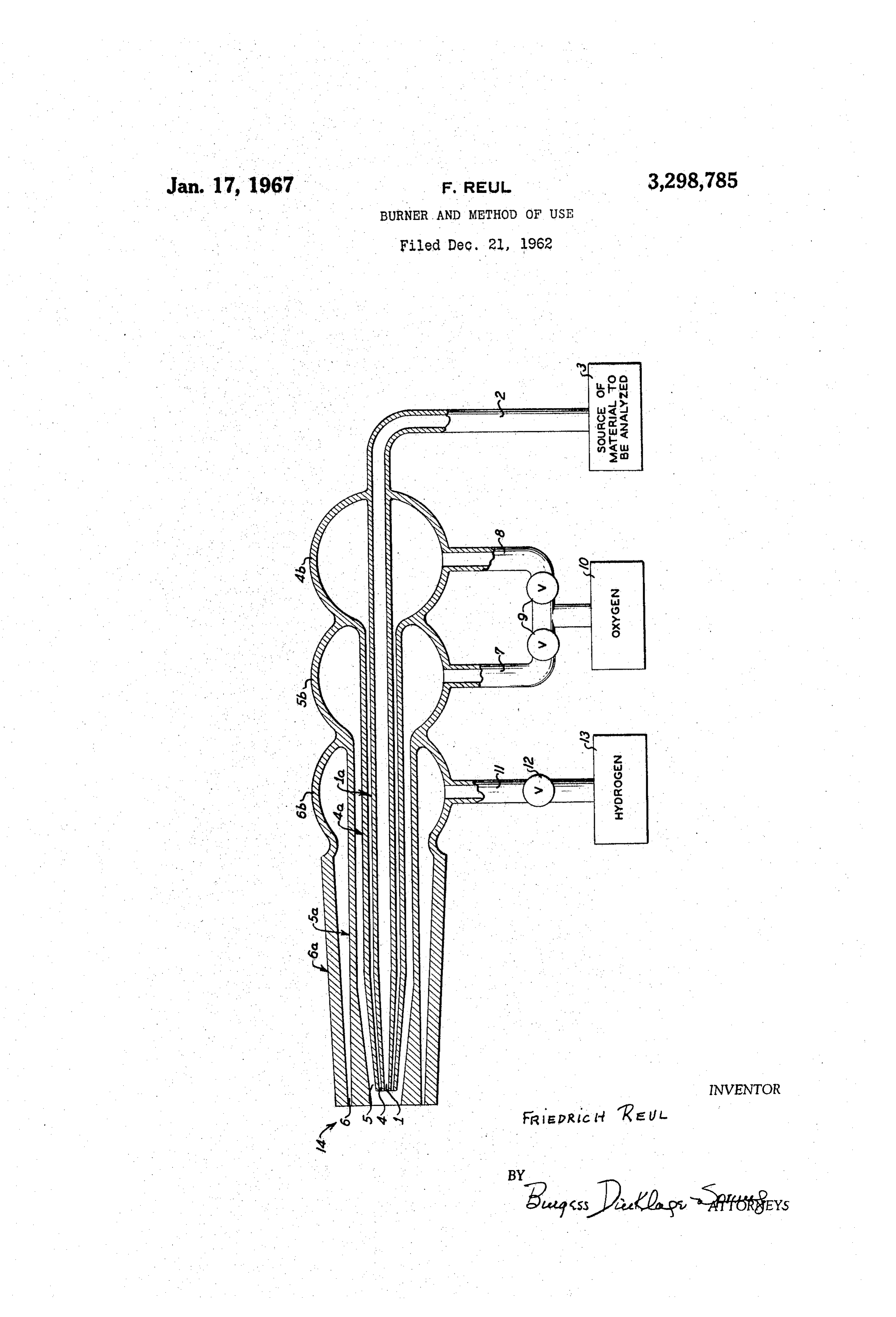
the second passageway (first annular passageway) and the 1. A burner comprising four concentrically disposed third passageway (second annular passageway). Prefer pipes providing a first passageway through the innermost ably, particularly where oxygen is passed through the sec pipe, a second passageway as an annulus about said first ond and third passageways, the cross-sectional flow area passageway, a third passageway as an annulus about said of the third passageway is larger than the cross-sectional O second passageway, and a fourth passageway as an annulus flow area of the second passageway. about said third passageway, each of said passageways The invention is further described in reference to the having an inlet end and an outlet end, and said inlet ends accompanying drawing, wherein an elevation view, par being disposed adjacent each other and said outlet ends tially a cross-section, of a device according to the inven being disposed adjacent each other, means for introducing tion is shown. fuel to said first passageway and means for introducing Referring to the drawing, four pipes 1a, 4a, 5a, and 6a material for facilitating burning of the fuel through the are disposed in concentric relationship and provide an remaining three passageways, said first, second, and third inner or first passageway 1, a second passageway or first passageways terminating short of said fourth passageway. annular passageway 4, a third passageway or second an 2. A burner according to claim 1, the cross-sectional nular passageway 5, and a fourth passageway or third flow area of said passageways adjacent the outlet ends annular passageway 6. The pipes terminate in outlet ends thereof, decreasing in the directions of the outlet ends. indicated by the arrow 14, and the pipes. 1a and 4ater 3. A burner according to claim 1, the cross-sectional minate short of the point of termination of the pipes 5a flow area of said third passageway adjacent the outlet ends and 6a, so that the passageways, 1,4 and 5 terminate short being larger than the cross-sectional flow area of said sec of the termination of the passageway 6. The pipe 1a ex ond passageway adjacent the outlet ends. tends rearwardly from the outlet ends 14 and is integral 4. A burner according to claim 2, the cross-sectional with a connecting link 2 which connects the pipe 1a with flow area of said third passageway adjacent the outlet ends a source of fuel or material to be analyzed. The material being larger than the cross-sectional flow area of said Sec to be analyzed is contained in the container 3. . The pipe ond passageway adjacent the outlet ends. 4a extends rearwardly and communicates with the bulb 30 5. A burner according to claim 1, said pipes being 4b. In similar manner, the pipe. 5a extends rearwardly quartz.
and communicates with the bulb 5b. The bulbs 4b and 6. A burner according to claim , the two inner pipes 5b are communicated respectively with a container 10, by terminating in a plane perpendicular to the axis of the the connecting links 8 and 7. The connecting links 8 and burner and the two outer pipes terminating in a plane 7 are each outfitted with a valve 9, whereby the flow in 3 5 perpendicular to the axis of the burner. the pipes 4a and 5a can be proportioned as is desired. 7. The method of burning a fuel which comprises Oxygen can be contained in the container 10. The Outer burning the fuel with a burner comprising four concen pipe 6a extends rearwardly and connects with a bulb 6b, trically disposed pipes providing a first passageway through and this bulb is communicated with a container 13 by a the innermost pipe, a second passageway as an annulus connecting link 11. The connecting link 11 is outfitted 40 about said first passageway, a third passageway as an with a valve 12. Hydrogen for supporting the combustion annulus about said second passageway, and a fourth pas can be contained in the container 13. sageway as an annulus about said third passageway, each . The cross-sectional flow area of the various passage of said passageways having an inlet end and an outlet end, ways, adjacent the outlet ends 14, decreases toward the and said inlet ends being disposed adjacent each other and outlet end. The two inner pipes 1a and 4a converge ad said outlet ends being disposed adjacent each other, said jacent the outlet end and provide these pipes as burner first, second, and third passageways terminating short of nozzles. The cross-sectional flow area of the second pas said fourth passageway whereby three shortened passage sageway (first annular passageway) is smaller than the ways are provided, passing fuel for combustion through cross-sectional flow area of the third passageway (sec said first passageway, passing oxygen through said second ond annular passageway). The wall. --of the pipe 5a, ad 50 and third passageways, and passing a combustible ma jacent the outlet ends 14, diverges to provide, on the one terial through said fourth passageway. hand, the desired reduction of cross-sectional flow area 8. The method of claim 7, wherein the combustion ma for the third passageway 5 and, on the other hand, the terial passed through the fourth passageway is hydrogen. desired cross-sectional flow area for the fourth passage
References Cited by the Examiner
The burner can be constructed of quartz, as is known UNITED STATES PATENTS for such burners, and the outer pipe 6a can be a ground section. .. . . •- .. 2,121463 6/1938 Wisdom --------- 23-259.5 X The burner operates in a known manner as a suction 3,141,741 7/1964 Hoel et al. ---------------- 23-253 burner. In use, it can be placed in a fired tube, as is 60 MORRIS O. WOLK, Primary Examiner.
While the invention has been described with reference to JAMES H.TAYMAN, JR., Examiner.
Provenance
- Collection
- Cited prior art
- Original PDF
- patentimages.storage.googleapis.com →
- Filed
- 1962-12-21
- Pages
- 3
- Method
- pdftotext (the PDF's own text layer) + pdftoppm 300dpi page scans
- Source
- Google Patents bibliographic record
- Granted
- 1967-01-17
- Inventors
- Reul Friedrich; Heraeus Schott Quarzschmelze GmbH
- Transcribed from
- patentimages.storage.googleapis.com →