patent · US5040970
Burner construction and method of making the same
20 August 1991
Page 1 — bibliographic record
United States Patent (19) 11 Patent Number: 5,040,970 Riehl (45) Date of Patent: Aug. 20, 1991 54) BURNER CONSTRUCTION AND METHOD 2408096 7/1979 France ................................ 431/264 OF MAKING THE SAME 1450i 53 9/1976 United Kingdom ................ 431/266 (75) Inventor: Fred Riehl, Greenburg, Pa. Primary Examiner-James C. Yeung Attorney, Agent, or Firm-Candor, Candor & Tassone (73) Assignee: Robertshaw Controls Company,
Richmond, Va. 57) ABSTRACT 21 Appl. No.: 508,799 A burner construction and method of making the same are provided, the burner construction comprising a 22 Filed: Apr. 12, 1990 burner body having a chamber therein and having op (51) Int. Cl................................................. F23Q 3/00 posed ends one of which is open to the chamber and the (52) U.S. C. .................................... 431/264; 431/266; other of which has structure for interconnecting a 431/354; 126/39 R; 126/39 E source of fuel to the chamber, and a removable cap (58) Field of Search ................. 126/39 R, 39 E, 39 F, closing the one end of the body, the cap having opposed 126/39 N, 39 Ki: 431/264, 266, 263, 354, 355; sides and an annular peripheral edge interconnecting 239/553.3, 567, 390, 396 the opposed sides together, the burner construction having ports interconnecting the chamber to the exte (56) References Cited rior of the burner construction and through which the U.S. RATENT DOCUMENTS fuel can issue to burn externally to the burner construc 1,004,291 9/1911 Merrill . tion, the cap having an annular groove in one of the 4,773,383 9/1988 Le Monnier de Gouville et opposed sides thereof ang inboard of the peripheral al. .................................. 126/39 R edge thereof, the burner body having a projection dis 4,846,671 7/1989 Kwiatek .............................. 431/266 posed in the groove to hold the cap on the one end of
FOREIGN PATENT DOCUMENTS
the burner body in its closing position thereof.
i 109625 6/1961 Fed. Rep. of Germany ...... 431/343 11 Claims, 4 Drawing Sheets
39 35 62 6465 3O
- SiNRSXSG
2 65 5% 90
area: a
Page 2
Drawing sheet — no readable text.
Page 3
Drawing sheet — no readable text.
Page 4
Drawing sheet — no readable text.
Page 5
Drawing sheet — no readable text.
Page 6
struction, the cap means having an annular groove
BURNER CONSTRUCTION AND METHOD OF means in one of the opposed sides thereof and inboard MAKING THE SAME of the peripheral edge means thereof, the burner body means having projection means disposed in the groove
BACKGROUND OF THE INVENTION 5 means to hold the cap means on the one end means of 1. Field of the Invention the burner body means in its closing position thereof. This invention relates to a new burner and to a new It is another feature of this invention to provide a new method of making such a burner construction. burner construction that has unique spacing of the port 2. Prior Art Statement means and the carry-over land means thereof so as to It is known to provide a burner construction compris O provide good combustion performance. ing a burner body means having a chamber means In particular, it was found according to the teachings therein and having opposed end means one of which is of this invention that one of the body means and the cap open to the chamber means and the other of which has means of the burner construction can have an annular means for interconnecting a source of fuel to the cham surface means interrupted by a plurality of radially ber means, and a removable cap means closing the one 15 disposed groove means that are spaced apart by land end means of the body means, the cap means having means and that define a generally repeating pattern of a opposed sides and an annular peripheral edge means set of a certain number of the groove means and the interconnecting the opposed sides together, the burner land means separated from the next adjacent set of the construction having port means interconnecting the certain number of the groove means and the land means chamber means to the exterior of the burner construc- 20 by one of the land means that is not part of the sets and tion and through which the fuel can issue to burn exter that has an annular or circumferential length that is nally to the burner construction. For example, see the longer than the annular or circumferential length of any Merrill U.S. Pat. No. 1,004,291 and the Kwiatek U.S. one of the land means of the sets separated thereby, Pat. No. 4,846,671. For example, another embodiment of this invention It is also known to provide a burner construction 25 comprises a burner construction comprising a burner comprising a burner body means having a chamber body means having a chamber means therein and hav means therein and having opposed end means one of ing opposed end means one of which is open to the which is open to the chamber means and the other of chamber means and the other of which has means for which has means for interconnecting a source of fuel to interconnecting a source of fuel to the chamber means, the chamber means, and a removable cap means closing 30 the one end means of the body means, the burner con and a removable cap means closing the one end means struction having port means interconnecting the cham of the body means, the burner construction having port means interconnecting the chamber means to the exte ber means to the exterior of the burner construction and through which the fuel can issue to burn externally to rior of the burner construction and through which the the burner construction, the other of the opposed end 35 tion, oneissue fuel can to burn externally to the burner construc of the body means and the cap means having means of the body means having a generally cylindrical portion having a free end and a fuel flow passage lead an annular surface means interrupted by a plurality of radially disposed groove means that are spaced apart by ing from the free end to the chamber means, and an land means of the annular surface means and that define orifice adaptor carried by the portion to feed fuel from the source into the passage at the free end of the por- 40 a generally repeating pattern of a set of a certain num tion. For example, see the aforementioned Merrill U.S. ber of the groove means and the land means separated Pat. No. 1,004,291 and the aforementioned Kwiatek from the next adjacent set of the certain number of the U.S. Pat. No. 4,846,671. groove means and the land means by one of the land means that is not part of the sets and that has an annular
SUMMARY OF THE INVENTION 45 length that is longer than the annular length of any one It is one feature of this invention to proVide a new of the land means of the sets separated thereby and burner construction that utilizes unique means for locat wherein the other of the body means and the cap means ing the burner cap means in its proper position without has an annular surface means cooperating with the an requiring great manual dexterity. nular surface means that has the groove means therein In particular, it was found according to the teachings 50 to close the groove means on one end thereof whereby of this invention that the burner cap means can be pro the groove means define the port means. vided with an annular groove means which will receive It is another feature of this invention to provide a new projection means of the burner body means therein so as burner construction that has unique igniter means for to hold the cap means in its proper position on the igniting the fuel issuing from the burner construction. burner body means. 55 In particular, it was found according to the teachings For example, one embodiment of this invention com of this invention that one of the land means that is dis prises a burner construction comprising a burner body posed between a pair of groove means that form port means having a chamber means therein and having means of the burner construction can have an igniter opposed end means one of which is open to the chamber receiving slot means formed therein so that an igniter means and the other of which has means for intercon- 60 assembly can have a part thereof disposed in such slot necting a source of fuel to the chamber means, and a eaS.
removable cap means closing the one end means of the For example, another embodiment of this invention body means, the cap means having opposed sides and an comprises a burner construction comprising a burner annular peripheral edge means interconnecting the op body means having a chamber means therein and hav posed sides together, the burner construction having 65 ing opposed end means one of which is open to the port means interconnecting the chamber means to the chamber means and the other of which has means for exterior of the burner construction and through which interconnecting a source of fuel to the chamber means, the fuel can issue to burn externally to the burner con a removable cap means closing the one end means of the
Page 7
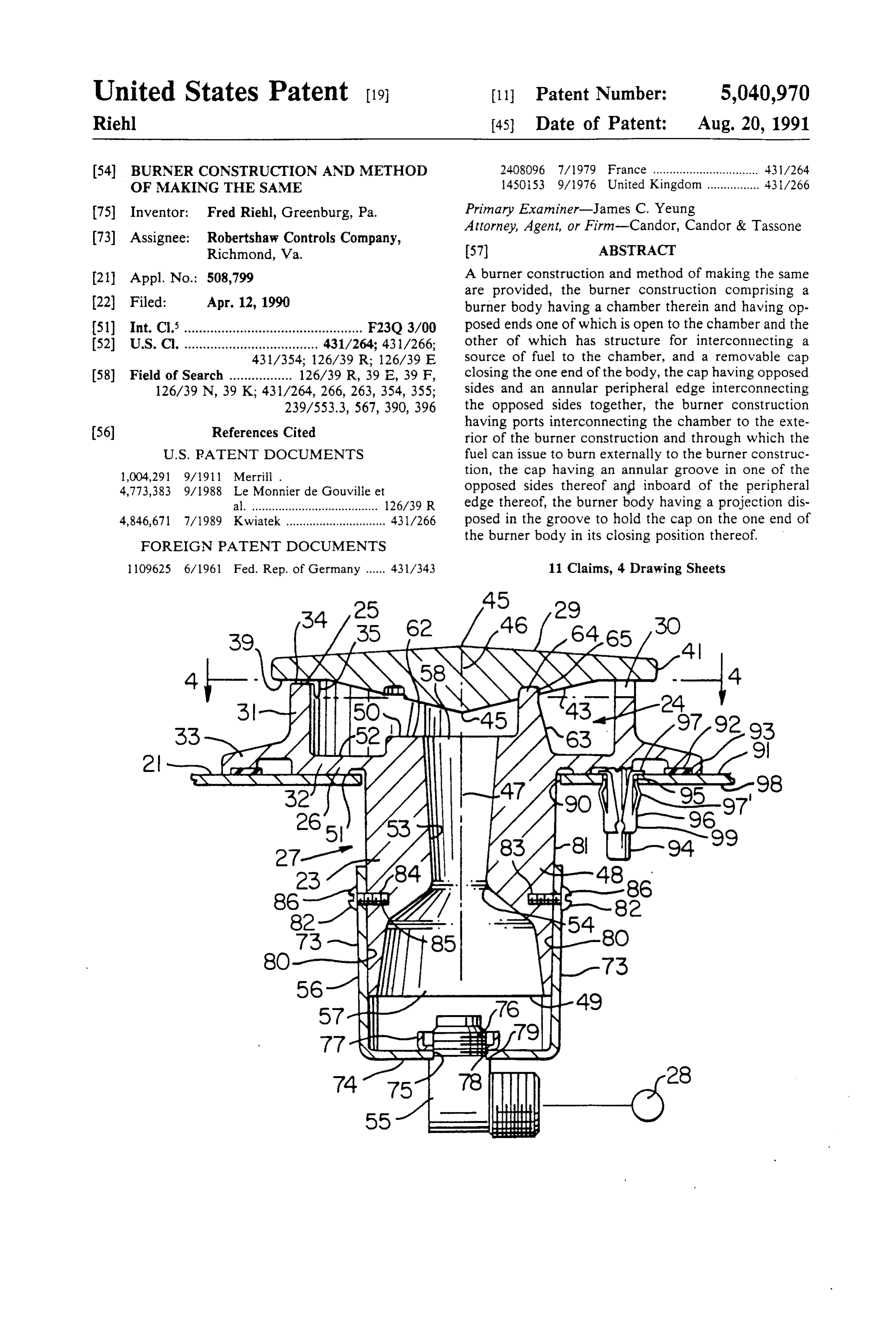
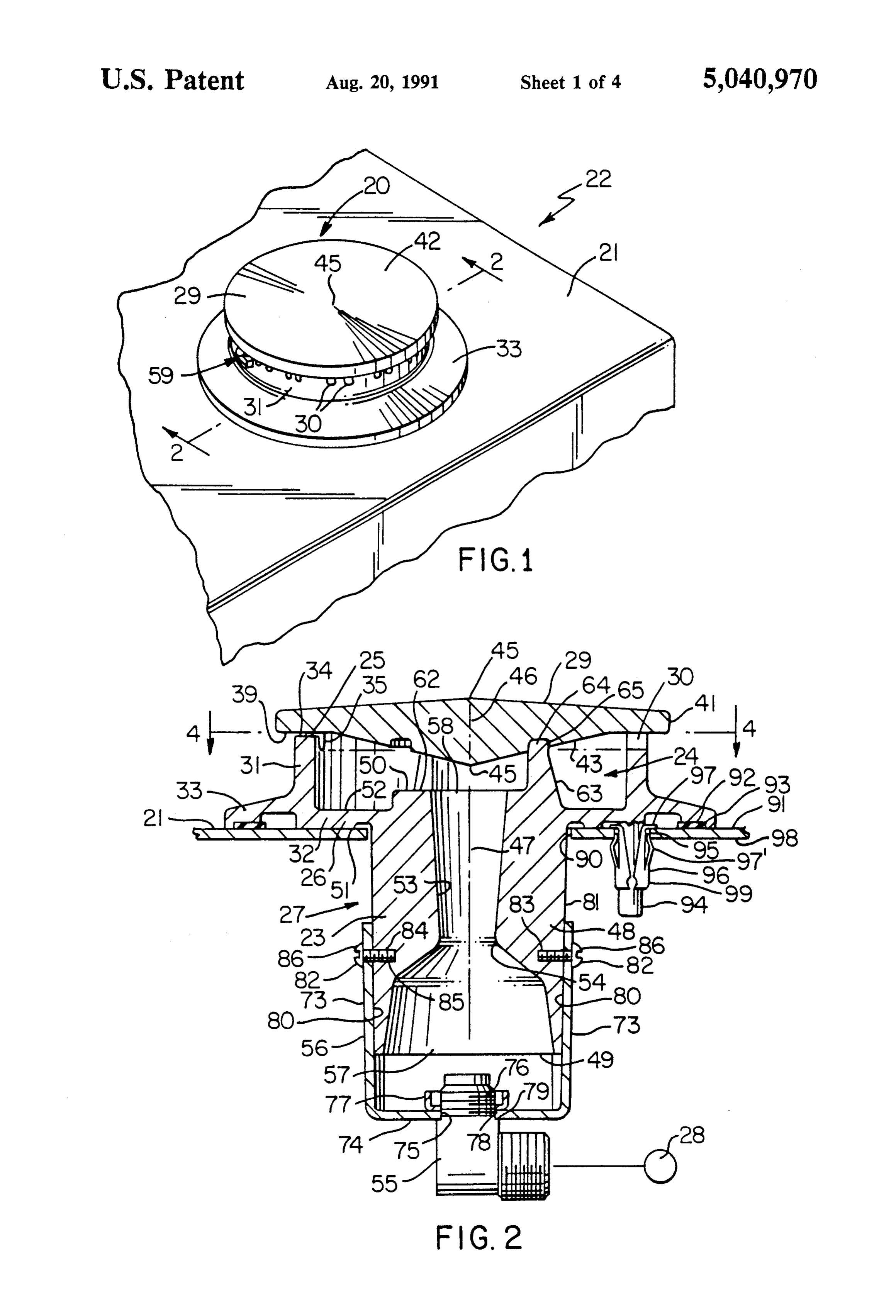
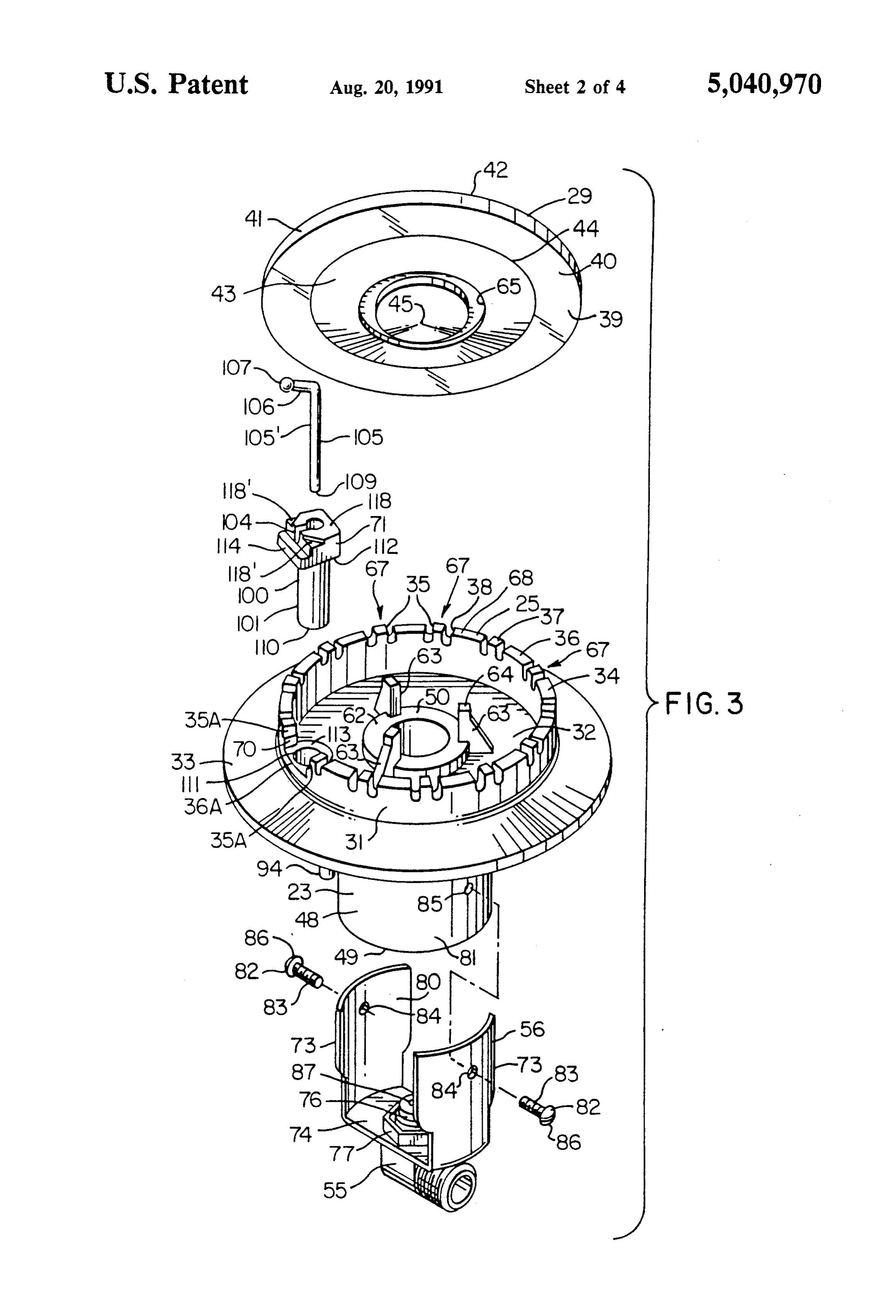
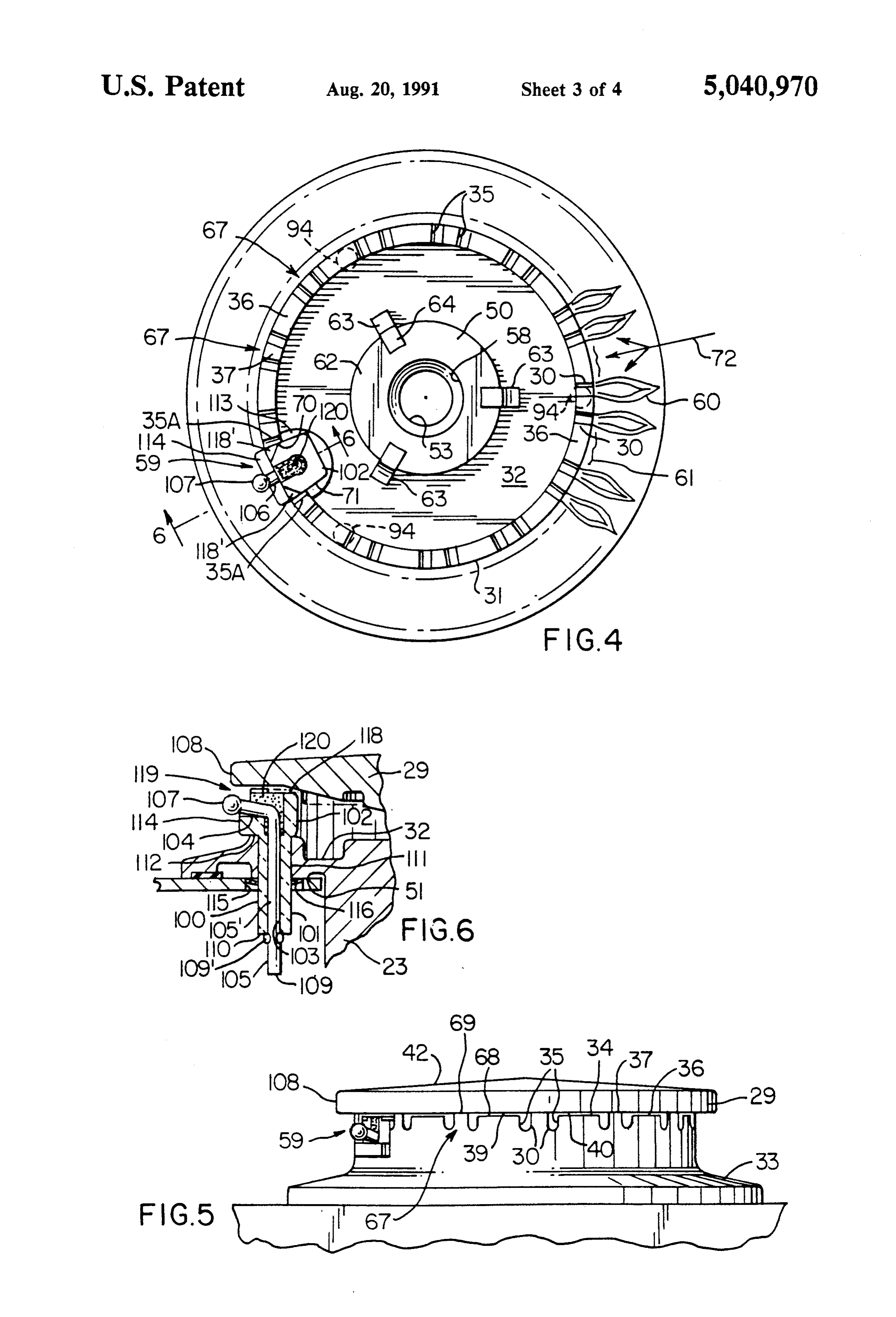
burner body means, the burner construction having FIG. 2 is an enlarged fragmentary cross-sectional port means interconnecting the chamber means to the view taken on line 2-2 of FIG. i. exterior of the burner construction and through which FIG. 3 is an exploded perspective view of the various the fuel can issue to burn externally to the burner con parts of the burner construction of FIGS. 1 and 2. struction, one of the body means and the cap means 5 FIG. 4 is a cross-sectional view of the burner con having an annular surface means interrupted by a plu struction of FIG. 2 and is taken in the direction of the rality of radially disposed groove means that are spaced arrows 4-4 of FIG. 2.
apart by land means of the annular surface means one of FIG. 5 is a fragmentary side view of the burner con which has an igniter receiving slot means therein and struction of FIG. 1 and illustrates the igniter assembly wherein the other of the body means and the cap means O thereof.
has an annular surface means cooperating with the an FIG. 6 is a fragmentary cross-sectional view taken on nular surface means that has the groove means therein line 6-6 of FIG. 4 and illustrating the igniter assembly to close the groove means on one end thereof whereby of the burner construction.
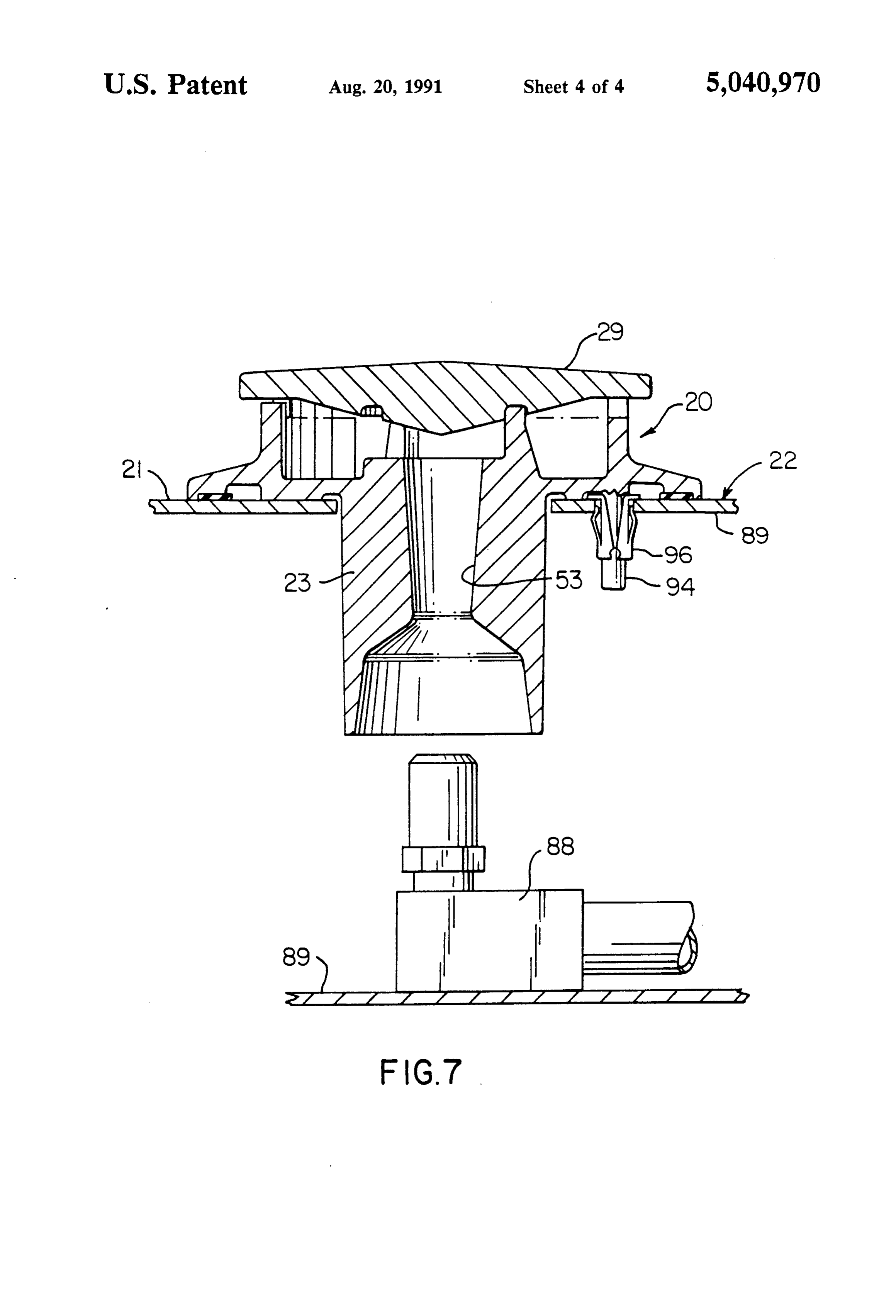
the groove means defines the port means, and an igniter FIG. 7 is a view similar to FIG. 2 and illustrates the assembly having a part thereof disposed in the slot 15 burner construction of this invention being utilized with leanS. a remote orifice adaptor.
It is another feature of this invention to provide a new DESCRIPTION OF THE PREFERRED burner construction that is adapted to be installed with EMBODIMENTS a remote coaxial orifice adaptor arrangement and has 20 unique means for being converted so as to carry an While the various features of this invention are here orifice adaptor as a part thereof, if desired. inafter illustrated and described as being particularly In particular, it was found according to the teachings adapted to provide a burner construction for being of this invention that a unique generally U-shaped be sealed into the range top of a cooking apparatus, it is to bracket can be detachably mounted to the burner body 25 understood that the various features of this invention means of the burner construction and carry an orifice can be utilized singly or in various combinations thereof to provide a burner construction for other apparatus as adaptor in the proper position for feeding fuel to the desired.
burner construction.
For example, another embodiment of this invention theTherefore, this invention is not to be limited to only embodiments illustrated in the drawings, because comprises a burner construction comprising a burner 30 drawings are merely body means having a chamber means therein and hav the wide variety of uses of utilized to illustrate one of the this invention.
ing opposed end means one of which is open to the The burner construction of this invention is of a type chamber means and the other of which has means for that is similar to the burner constructions that are set interconnecting a source of fuel to the chamber means, forth in applicant's copending patent application, Ser. a removable cap means closing the one end means of the 35 No. 448,935, filed Dec. 12, 1989. However, the burner body means, the burner construction having port means construction of this invention has many features that are interconnecting the chamber means to the exterior of unique and are not provided in the burner constructions the burner construction and through which the fuel can of such copending patent application as will be apparent issue to burn externally to the burner construction, the hereinafter.
other of the opposed end means of the burner body Referring now to FIGS. 1-3, the new burner con means having a generally cylindrical portion having a struction free end and a fuel flow passage leading from the free reference of this invention is generally indicated by the end to the chamber means, and an orifice adaptor car a range top surface2021 numeral and is illustrated as being sealed to of a cooking apparatus that is ried by the portion to feed fuel from the source into the generally indicated by the reference numeral 22, the passage at the free end of the portion, the burner con 45 burner construction 20 comprising a burner body means struction comprising a generally U-shaped bracket de 23 having a chamber means 24 therein fined by two legs respectively interconnected to the posed end means 25 and 26 with the end and having op portion of the body means and a cross member that open to the chamber means 24 and the other end25means means being interconnects the legs together and carries the orifice 26 being closed and having means that is generally adaptor. 50 indicated by the reference numeral 27 for interconnect Accordingly, it is an object of this invention to pro ing a source 28 of fuel with the chamber means 24 in a vide a new burner construction having one or more of manner hereinafter set forth. the novel features of this invention as set forth above or The burner construction 20 comprises a removable hereinafter shown or described. cap means 29 closing the open end means 25 of the Another object of this invention is to provide a new 55 burner body means 23, the burner construction 20 hav method of making such a burner construction, the ing a plurality of port means 30 interconnecting the method of this invention having one or more of the chamber means 24 to the exterior of the burner con novel features of this invention as set forth above or struction 20 and through which fuel can issue to burn hereinafter shown or described. externally to the burner construction 20 in a manner Other objects, uses and advantages of this invention well known in the art. For example, see the aforemen are apparent from a reading of this description which tioned Merrill U.S. Pat. No. 1,004,291 and the afore proceeds with reference to the accompanying drawings mentioned Swiatek U.S. Pat. No. 4,846,671, whereby forming a part thereof and wherein: these two patents are being incorporated into this dis BRIEF DESCRIPTION OF THE DRAWINGS 65 closure by this reference thereto.
While the burner body means 23 and removable cap
FIG. 1 is a fragmentary top perspective view illus means 29 of the burner construction 20 of this invention trating the new burner construction of this invention can be formed of any suitable material or combination mounted in a range top of a cooking apparatus. of materials, such as metallic material, one working
Page 8
embodiment thereof has the body means 23 and cap cent flames 60 at the land means 36 in a unique manner means 29 each formed of die cast aluminum RMS-105 hereinafter set forth.
with the body means 23 being a one-piece member and The free end 50 of the portion 48 of the burner body with the open end means 25 thereof being defined by an means 23 defines an annular surface means 62 that sur annular wall 31 extending upwardly from a wall 32 that rounds the outlet end 58 of the passage 53 and extends defines the closed end means 26 of the body member 23, beyond the surface 52 of the wall 32 as illustrated in the wall means 32 having an annular extension 33 for FIG. 3. The burner body means 23 includes three uni extending outboard of the upstanding annular wall 31 as formly spaced apart projections 63 disposed in a circu illustrated. lar array about the free end 50 of the cylindrical portion In this manner, the two main parts of the burner O 28 and having free end portions 64 which are adapted to construction 20, namely the burner body means 23 and be respectively received in an annular groove means 65 the cap means 29 can be manufactured as two castings formed in the side 40 of the cap means 29, the groove without machining processes and thereby having a re means 65 being substantially concentric to the longitu duced manufacturing cost. dinal axis 46 of the cap means 29 which joins the center The annular wall 31 of the body means 23 has an 15 points 45 thereof whereby the cap means 29 is axially annular substantially flat top surface means 34 inter oriented on the burner body means 23 in any desired rupted by a plurality of radially disposed and spaced rotational position thereof while still having the axis 46 apart U-shaped grooves 35 disposed in the circular thereof substantially coaxial with the axis 47 of the burner body means 23 so as to properly close the open array pattern as illustrated in FIGS. 3 and 4, the groove 20 ends means 35 being separated by ungrooved land means 36 38 of the grooves 35.
and 37 of the annular surface means 34 in a unique pat readily Thus, it can be seen that the cap means 29 can be tern arrangement that will be hereinafter set forth. removed from the burner body means 23 and be readily replaced thereon in any rotational position
The grooves 35 in the body member 23 are adapted to thereof be respectively closed at the open ends 38 thereof by a 25 tions 63 by having the free end means 64 of the projec substantially flat annular surface means 39 formed on a manner illustratedin intheFIG.
received annular groove means 65 in the side 40 of the cap means 29 when the cap means 29 is manual dexterity to properly2 orient without requiring great the cap means 29 disposed in its closing position on the open end 25 of the relative to the body means 23.
burner body means 23 in the manner illustrated in
FIGS. 2 and 5 so as to cooperate with the grooves 35 to 30 ingsIn of addition, it has been found according to the teach this invention that the fingers or projections 63 define the port means 30 previously set forth. provide obstructions to the fuel air mixture issuing out The cap means 29 has an annular peripheral edge of the outlet end 58 of the passage means 53 into the means 41 that interconnects the side 40 of the cap means chamber 24 of the burner construction 20 so as to pro 29 with an opposed side 42 thereof, the side 42 being vide for increased fuel air mixing of the primary air and generally conical and the side 40 having a central coni 35 the fuel through the resulting turbulence thereof caused cal portion 43 that has its larger base 44 joining with the by the obstructions 63 prior to the fuel air mixture exit flat annular portion 40 thereof as illustrated whereby ing through the port areas 30 so that good combustion the respective apexes 45 of the conical side 42 and of the is provided by the burner construction 20 of this inven conical section 43 of the side 40 define a center axis 46 tion.
of the cap means 29 that is disposed substantially coaxial The groove means 35 that are formed in the wall 31 with a longitudinal axis 47 of the burner body means 23 of the burner body means 23 to subsequently form the as illustrated in FIG. 2 when the cap means 29 is in its port means 30, are so constructed and arranged that the closed position on the burner body means 23. same define a substantially repeating pattern of a set 67 The burner body means 23 has the means 27 thereof of two grooves 35 separated from each other by the comprising a cylindrical portion 48 extending from the 45 land means 37 and then separated from the next set 67 of closed end 26 thereof and being substantially coaxial a pair of grooves 35 and their respective intermediate with the longitudinal axis 47 of the burner body means land means 37 by a large land means 36 that has an 23, the cylindrical portion 48 having opposed free end annular or circumferential length greater than the annu means 49 and 50 respectively extending from opposed lar or circumferential length of each of the lands 37 of sides 51 and 52 of the wall 32 and being respectively 50 the two adjacent sets 67 as illustrated. In addition, the interrupted by a passage means 53 passing longitudi separating lands 36 each has a free end flat surface 68 nally therethrough and defining an intermediate Ven that is recessed below the free end flat surfaces 69 of the turi throat portion 54 for a purpose well known in the lands 37 as will be apparent hereinafter so as to provide art. In this manner, an orifice adaptor 55 that is carried for the carry-over flame means 61 previously described by a unique bracket structure 56 of this invention in a 55 One of the larger land means 36 of the burner con manner hereinafter set forth is adapted to direct fuel struction 20 of this invention is indicated by the refer from the source 28 into an inlet end 57 of the passage ence numeral 36A in FIG. 3 and part of the groove means 53 to issue out of an outlet end 58 thereof into the means 35A on each side of the land means 36A are cut chamber means 24 after passing through the Venturi away to form a substantially rectangular slot means 70 throat means 54. Such fuel flowing into the chamber 24 60 therein to receive an enlarged substantially rectangular passes out through the port means 30 to be ignited by an end 71 of the igniter assembly 59 therein in the manner igniter assembly of this invention that is generally indi illustrated in FIGS. 4 and 6 and hereinafter set forth cated by the reference numeral 59 and will be hereinaf It has been found in one working embodiment of the ter set forth whereby the ignited fuel will propagate burner construction 20 of this invention wherein the around the burner construction 20 to produce the flame 65 outer diameter of the wall 31 of the burner body means pattern that is illustrated in FIG. 4 wherein main flames 23 at the annular surface means 34 is approximately 60 are issuing from the port means 30 and carry-over 2.375 inches and the inner diameter of the wall 31 at the flame means 61 are provided between each pair of adja annular surface means 34 is approximately 2.125 inches,
Page 9
the grooves 35 each has a width at the open end 38 apparatus 22 has an orifice adaptor means 88 mounted thereof of approximately 0.062 of an inch and a depth of to a structure 89 of the cooking apparatus so as to be approximately 0.115 of an inch while the U-shaped end separate or remote from the burner construction 20 as thereof is defined by a radius that is one-half of the illustrated in FIG. 7. In this manner, the premounted width of the respective groove 35. The outer surfaces orifice adaptor 88 permits the fuel supply lines to be 68 of the separating lands 36 are each recessed below assembled to the cooking apparatus 22 and be leak the outer surfaces 69 of the lands 37 by approximately tested prior to the placing of the burner constructions 0.015 of an inch. The annular or circumferential length 20 of this invention in position on the top surface means of the surface 68 of each separating land 36 is approxi 21 and the passage means 53 thereof will still be coaxi mately 0.315 of an inch and the annular or circumferen 10 ally aligned with the remote orifice adaptors 88. tial length of the surface 69 of each land 37 is approxi However, as fully illustrated in FIGS. 1-6, the burner mately 0.125 of an inch. construction 20 of this invention readily permits the It has been found in the above working embodiment bracket member 56 to be secured thereto by the two for the grooves 35 and lands 36 and 37 that the carry screws 82 to convert the burner assembly of FIG. 7 to over flames 61 between each set 67 of grooves 35 15 an integral orifice burner design concept wherein the caused by the fuel flowing outwardly from the chamber orifice adaptor 55 is carried by the bracket means 56 as 24 between the cap means 29 and the lowered surfaces previously set forth and as illustrated in FIG. 2. 68 of the lands 36 are sufficient to propagate the main While the burner body means 23 of the burner con burner flames 60 around the burner circumference and struction 20 of this invention can be mounted to the top do not interfere with the vital induction of secondary 20 surface means 21 of the cooking apparatus 22 in any air at each land 36 as represented by the arrow 72 in suitable manner, the embodiment of the burner con FIG. 4 so as to complete combustion of the outer mantle struction 20 illustrated in the drawings is adapted to of the main burner flames 60. have the portion 48 of the burner body means 23 in The unique bracket 56 of this invention comprises a serted through a suitable circular opening 90 formed U-shaped structure as illustrated in FIG. 3 that defines 25 through a top wall 91 of the cooking apparatus 22 that two legs 73 that are joined together by a cross member has the top surface means 21 as illustrated in FIG. 2 and 74 that has an opening 75 passing centrally there be sealed thereto by a conventional annular sealing through and receiving a threaded end 76 of the orifice means 92 received in a groove means 93 in the wall adaptor 55 therethrough so that the orifice adaptor 55 extension 33 as illustrated. If desired, the annular sealing can be fastened to the bracket 56 by a nut means 77 30 means 92 can actually space the wall means 32 of the threaded on the threaded end 76 of the adaptor 55 to burner body means 23 slightly above the top surface 21 sandwich a peripheral edge means 78 of the cross mem of the wall means 91 in order to prevent heat of the ber 74 of the bracket 56 between the nut 77 and an burner construction 20 being transferred by conduction annular shoulder 79 of the orifice adaptor 55 in the to the wall 91 through intimate contact of the metallic manner illustrated in FIG. 2. 35 material of the burner construction 20 with the wall While the bracket 56 can be formed of any suitable means 91.
material and in any suitable manner, one working em In any event, the wall means 32 of the burner body 23 bodiment of the bracket 56 comprises a sheet metal has a plurality, such as three, of tapering projections 94 member that has been suitably cut, stamped and bent formed integrally there with and extending downwardly into the configuration illustrated. therefrom so as to be adapted to pass through cooperat The legs 73 of the bracket member 56 define arcuate ing openings 95 through the wall 91 at the same time inner surface means 80 that are adapted to mate with that the portion 48 of the burner body means 23 is being large areas of the cylindrical external peripheral surface inserted through the large opening 90, the projections means 81 of the portion 48 of the burner body means 23 94 being held in the inserted position thereof by conven in the manner illustrated in FIG. 2 and be detachably 45 tional spring clip means 96 that respectively have en fastened directly thereto by threaded fastening mem larged flange means 97 resting on the top surface 21 of bers or screws 82 respectively having threaded shank the wall means 91 and spring fingers 97 engaging portions 83 thereof passing through suitable openings 84 against the under surface 98 of the wall means 91 so that in the legs 73 and being received in threaded openings the lower C-shaped split ends 99 thereof will respec 85 formed in the portion 48 of the burner body means 23 50 tively spring engage against the projections 94 to tend in the manner illustrated in FIG 2 wherein enlarged to prevent the same from being pulled out of the clip heads 86 of the fastening members 82 sandwich the legs means 96 in a conventional manner for such type of clip 73 against the surface means 81 of the portion 48 of the CaS.
burner body means 23 as illustrated in FIG. 2. Because Thus, it can be seen that it is a relatively simple matter of the relatively long arcuate inner surfaces 80 of the 55 to first insert the clip means 96 through the opening legs 73, it can be seen that the bracket member 56 can means 95 in the wall means 91 of the cooking apparatus not rotate about the axis of the fastening members 82 22 and then push the projections 94 of the burner body whereby the center or orifice opening 87, FIG. 3, of the means 23 through such clip means 96 as the cylindrical orifice adaptor 55 will be substantially disposed coaxial projection 48 of the burner body means 23 is being with the longitudinal axis 47 of the passage 53 for 60 inserted through the main opening 90 so as to hold the proper injection of the fuel flow into the Venturi throat burner body means 23 in the fully inserted condition 54 of the passage means 53. illustrated in FIGS. 2 or 7. However, it can readily be seen that the bracket However, as previously stated other means can be member 56 can be readily detached from the burner utilized to mount the burner body means 23 in the open body means 23 by removing the fastening members 82 65 ing 90 of the cooking apparatus 22, as desired. whereby the burner body means 23 can be assembled to The unique igniter assembly 59 of this invention com the top surface means 21 of the cooking apparatus 22 in prises a one-piece electrically insulating member 100, the manner illustrated in FIG. 7 wherein the cooking such as a suitable ceramic material known as L 5 Stea
Page 10
tite, that has a cylindrical portion 101 extending from illustrated in FIG. 7, suitable control means (not shown) the enlarged rectangular head 102 thereof that actually will direct fuel from the fuel source 28 through the has a generally frusto-conical profile when looking orifice adaptor 55 or the orifice adaptor 88 into the down on the same. The cylindrical portion 100 has an Venturi throat means 54 of the passage means 53 that opening 103 passing completely therethrough and lead causes primary air to be drawn into the passage means ing from a transverse groove 104 formed in the head 102 53 in a manner well known in the art whereby the fuel whereby an electrode wire 105 can have a body portion air mixture is passed into the chamber means 24 where 105" thereof disposed through the opening 103 and an turbulence thereof is provided by the projections 63 in L-shaped bent end 106 that is angled upwardly received the manner previously described to provide for a good in the cooperating groove 104 as illustrated whereby a 10 air fuel mixture before the fuel issues out of the port ball-like free end 107 of the electrode wire 105 will be means 30 thereof. At the same time, other control means disposed in a proper position for sparking to an adjacent (not shown) provides for electrical sparking across the part 108 of the grounded cap means 29 when electrical spark gap 119 of the ignition assembly 59 and cap means current is passed through the wire means 105 by suitable 29 so that fuel issuing over the top 118 of the igniter electrical lead means being attached to the end 109 of 15 member 100 and out through the cutouts 118 of the the wire means 105 which projects out of the lower end igniter assembly 59 will be ignited by such sparking and 110 of the insulating member 100 and is upset at 109 to then through flame propagation will spread completely prevent movement of the electrode wire means 105 around the burner construction 20 through the propa relative to the ceramic member 100. gating flames 61 at the land means 36 and from flame In order to mount the igniter assembly 59 in place, the 20 means 60 to flame means 60 at the U-shaped grooves 35 wall 32 and land 36A are provided with a suitable open in the manner previously described so that the burner ing means 111 passing therethrough and through which construction 20 can be utilized for any desired purpose, the cylindrical portion 101 of the member 100 can pass such as a cooking purpose or the like. The igniter assem until the enlarged head 102 is received in the rectangu bly 59 can be so controlled that the same would also lar slot means 70 of the land means 36A by a lower 25 provide for flame rectification in a manner well known surface 112 thereof abutting against the surface 113 of in the art once the burner construction 20 has been the land 36A as illustrated in FIG. 6. If desired, a por ignited in the manner previously set forth. tion or lip 114 of the enlarged head 102 can extend Thus, it can be seen that the igniter assembly 59 of outwardly beyond the wall 31 of the burner body means this invention provides the cutouts 118' to meter the fuel 23 and beneath the electrode end 106 so as to prevent 30 flow for ignition and shielding that will direct the igni sparking from the ball end 107 of the electrode wire 105 tion sparks to a specified ground location at the point to structure of the burner body means 23 that is located 108 on the burner cap means 29 thereby ensuring a below the ball end 107 as illustrated. proper fuel mix and predictable spark for ignition of the The range top wall 91 has an opening 115 as illus same. Thereafter, rectification of the igniter probe 105 is trated in FIG. 6 so that the cylindrical portion 101 of 35 achieved by the external design of the ceramic member the member 100 can pass readily therethrough, a spring 100 at the enlarged head 102 thereof so as to provide clip 116 being telescopically disposed on the portion electrical conduction with the minimum stable turn 101 to engage against the underside 51 of the wall 32 to down flame size.
hold the igniter assembly 59 in the assembled relation Of course, when the control means disconnects the illustrated in FIG. 6. fuel source 28 from the orifice adaptor 55 or the orifice The enlarged head 102 of the insulating member 100 adaptor 88, fuel ceases to issue from the port means 30 of the igniter assembly 59 has a top surface 118 that is and thereby the burner construction 20 is turned off. spaced below the side 40 of the cap means 29 and that Thus, it can be seen that this invention provides a new has cutouts 118' therein at the forward edges thereof burner construction and a new method of making such that feed fuel issuing from the chamber means 24 into 45 a burner construction that will perform well with natu the adjacent grooves 35A to a spark gap area 119 above ral and LP fuels in the sealed burner applications the free end 107 of the igniter wire 105 so as to direct thereof.
additional ignition fuel into the gap 119 to add to the While the forms and methods of this invention now ignition fuel issuing directly to the gap 119 over the top preferred have been illustrated and described as re 118 of the member 100 from the chamber 24 so that 50 quired by the Patent Statute, it is to be understood that sparking across the gap 119 will ignite the fuel issuing other forms and method steps can be utilized and still from the chamber means 24. fall within the scope of the appended claims wherein In addition, in order to confine the sparking to the each claim sets forth what is believed to be known in gap 119 at the outer end 107 of the wire 105 so as to each claim prior to this invention in the portion of each prevent sparking from a part of the electrode portion 55 claim that is disposed before the terms "the improve 106 to the cap means 29 inside the ceramic area, suitable ment' and sets forth what is believed to be new in each ceramic potting material 120 can be disposed around claim according to this invention in the portion of each bent portion 106 of the wire 105 adjacent to the ball end claim that is disposed after the terms "the improve 107 thereof as illustrated. ment' whereby it is believed that each claim sets forth Therefore, it can be seen that it is a relatively simple 60 a novel, useful and unobvious invention within the pur method of this invention to make the burner construc view of the Patent Statute. tion 20 with or without the orifice adaptor 55 to be What is claimed is:
readily mounted in a top surface means 21 of a cooking 1. In a burner construction comprising a burner body apparatus 22 as illustrated in FIG. 2 or 7 so as to operatemeans having a chamber means therein and having in a manner now to be described. 65 opposed end means one of which is open to said cham After the burner construction 20 has been mounted in ber means and the other of which is open to said cham the surface 21 of the cooking apparatus 22 either in the ber means and the other of which has means for inter arrangement illustrated in FIG. 2 or in the arrangement connecting a source of fuel to said chamber means, and
Page 11
a removable cap means closing said one end means of means on one end thereof whereby said groove means said body means, said cap means having opposed sides define said port means.
and an annular peripheral edge means interconnecting 6. In a burner construction comprising a burner body said opposed sides together, said burner construction means having a chamber means therein and having having port means interconnecting said chamber means opposed end means one of which is open to said cham to the exterior of said burner construction and through ber means and the other of which has means for inter which said fuel can issue to burn externally to said connecting a source of fuel to said chamber means, and burner construction, the improvement wherein said cap a removable cap means closing said one end means of means has an annular groove means in one of said op said body means, said burner construction having port posed sides thereof and inboard of said peripheral edge O means interconnecting said chamber means to the exte means thereof, said burner body means having projec rior of said burner construction and through which said tion means disposed in said groove means to hold said fuel can issue to burn externally to said burner construc cap means on said one means of said burner body means tion, the improvement wherein one of said body means in its closing position thereof, said burner construction and said cap means has an annular surface means inter having a longitudinal axis that substantially passes 15 rupted by a plurality of radially disposed groove means through the center of said body means, said annular that are spaced apart by land means of said annular groove means of said cap means being substantially surface means and that define a generally repeating circular and having a center that is substantially coaxial pattern of a set of a certain number of said groove means with said axis whereby said cap means is oriented with and said land means separated from the next adjacent set said body means in any rotational position of said cap 20 of said certain number of said groove means and said means on said body means when said projection means land means by one of said land means that is not part of are received in said annular groove means. said sets and that has an annular length that is longer 2. In a burner construction comprising a burner body than the annular length of any one of said land means of means having a chamber means therein and having said sets separated thereby and wherein the other of said opposed end means one of which is open to said cham 25 body means and said cap means has an annular surface ber means and the other of which has means for inter means cooperating with said annular surface means that connecting a source of fuel to said chamber means, and has said groove means therein to close said groove a removable cap means closing said one end means of means on one end thereof whereby said groove means said body means, said cap means having opposed sides define said port means.
and an annular peripheral edge means interconnecting 30 7. A burner construction as set forth in claim 6 said, opposed sides together, said burner construction wherein each said set comprises two groove means having port means interconnecting said chamber means separated by one land means.
to the exterior of said burner construction and through 8. A burner construction as set forth in claim 7 which said fuel can issue to burn externally to said wherein each said groove means has a generally U burner construction, the improvement wherein said cap 35 shaped configuration throughout the radial length means has an annular groove means in one of said op thereof.
posed sides thereof and inboard of said peripheral edge 9. A burner construction as set forth in clairn 6 means thereof, said burner body means having projec wherein each said land means has a free end surface tion means disposed in said groove means to hold said means that faces said annular surface means of the other cap means on said one means of said burner body means of said body means and said cap means, said free end in its closing position thereof, the other of said opposed surface means of each of said land means that are not ends of said burner body means having a surface means part of said sets being spaced from said annular surface interrupted with an opening means that comprises said means of the other of said body means and said cap means for interconnecting said source of fuel to said means a greater distance than the distance said free end chamber means, said opening means being spaced from 45 surface means of each of said land means of said sets is said one side of said cap means and being disposed in spaced from said annular surface means of the other of board of said port means, said projection means being said body means and said cap means. disposed intermediate said opening means and part of 10. In a method of making a burner construction said port means to provide turbulence to said fuel as said comprising a burner body means having a chamber fuel moves from said opening means toward said part of 50 means therein and having opposed end means one of said port means. which is open to said chamber means and the other of 3. A burner construction as set forth in claim 2 which has means for interconnecting a source of fuel to wherein said burner construction has a longitudinal axis said chamber means, and a removable cap means clos that substantially passes through the center of said ing said one end means of said body means, said cap opening means, said annular groove means of said cap 55 means having opposed sides and an annular peripheral means being substantially circular and having a center edge means interconnecting said opposed sides to that is substantially coaxial with said axis. gether, said burner construction having port means 4. A burner construction as set forth in claim 3 interconnecting said chamber means to the exterior of wherein said projection means comprise a plurality of said burner construction and through which said fuel projections that are disposed in a circular array about 60 can issue to burn externally to said burner construction, said opening means. the improvement comprising the steps of forming said 5. A burner construction as set forth in claim 2 cap means to have an annular groove means in one of wherein said open end of said body means has an annu said opposed sides thereof and inboard of said periph lar surface means interrupted by a plurality of radially eral edge means thereof, and forming said burner body disposed and spaced apart groove means and wherein 65 means to have projection means disposed in said groove said one side of said cap means has an annular surface means to hold said cap means on said one end means of means cooperating with said annular surface means that said burner body means in its closing position thereof, has said groove means therein to close said groove forming said burner construction to have a longitudinal
Page 12
axis that substantially passes through the center of said comprising the steps of forming one of said body means body means, and forming said annular groove means of and said cap means to have an annular surface means Said cap means to be substantially circular and have a interrupted by a plurality of radially disposed groove center that is substantially coaxial with said axis means that are spaced apart by land means of said annu whereby said cap means is oriented with said body lar surface means and that define a generally repeating means in any rotational position of said cap means on said body means when said projection means are re pattern and said of a set of a certain number of said groove means land means separated from the next adjacent set ceived in said annular groove means, of said certain number of said groove means and said 11. In a method of making a burner construction land means by one of said land means that is not part of comprising a burner body means having a chamber 10 means therein and having opposed end means one of said sets and that has an annular length that is longer which is open to said chamber means and the other of that the annular length of any one of said land means of which has means for interconnecting a source of fuel to said sets separated thereby, and forming the other of said chamber means, and a removable cap means clos said body means and said cap means to have an annular ing said one end means of said body means, said burner 15 surface means cooperating with said annular surface construction having port means interconnecting said means that has said groove means therein to close said chamber means to the exterior of said burner construc groove means on one end thereof whereby said groove tion and through which said fuel can issue to burn exter means define said port means. nally to said burner construction, the improvement k s
Page 13
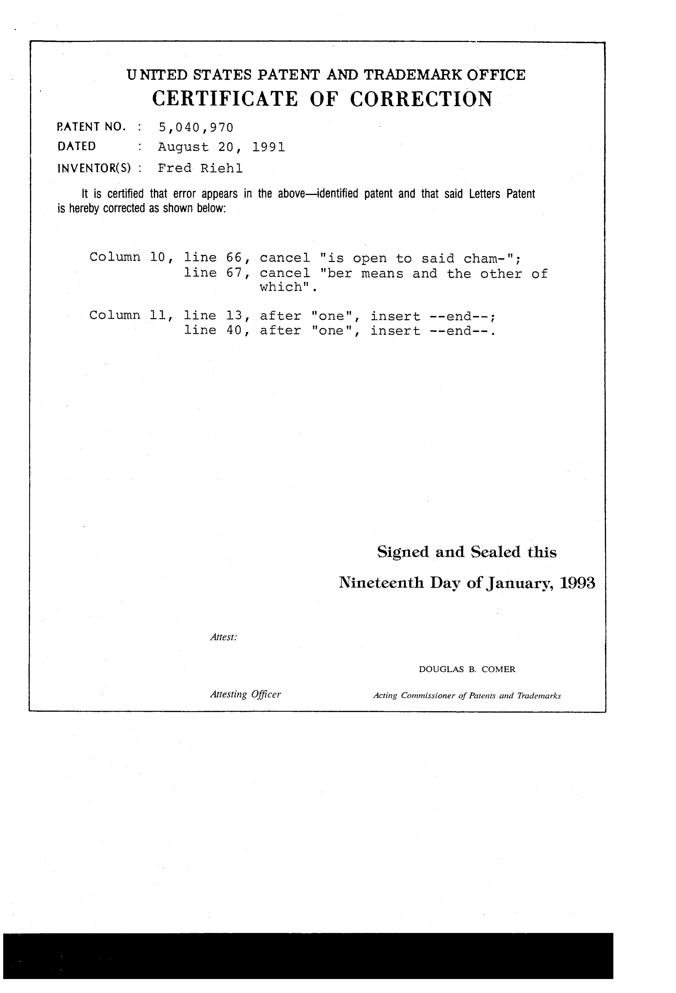
UNITED STATES PATENT AND TRADEMARK OFFICE
CERTIFICATE OF CORRECTION
NVENTOR(S) : Fred Riehl.
It is certified that error appears in the above-identified patent and that said Letters Patent is hereby COrrected as shown below:
Column lio, line 66, cancel "is open to said cham-"; line 67, Cancel "ber means and the other of
Column ll, line l3, after "one", insert -- end-- ; line 40, after "one", insert -- end--.
Signed and Sealed this
Nineteenth Day of January, 1993
DOUGLAS B. COMER
Attesting Officer Acting Commissioner of Patents and Trademarks
Provenance
- Collection
- Cited prior art
- Original PDF
- patentimages.storage.googleapis.com →
- Filed
- 1990-04-12
- Pages
- 13
- Method
- pdftotext (the PDF's own text layer) + pdftoppm 300dpi page scans
- Source
- Google Patents bibliographic record
- Granted
- 1991-08-20
- Inventors
- Fred Riehl; Robertshaw Controls Co
- Transcribed from
- patentimages.storage.googleapis.com →