patent · US5354264
Gas pressure driven infusion system by hydrogel electrolysis
11 October 1994
Page 1 — bibliographic record
United States Patent (19) [11] Patent Number: 5,354,264 Bae et al. 45) Date of Patent: Oct. 11, 1994 54) GAS PRESSURE DRIVEN INFUSION FOREIGN PATENT DOCUMENTS
SYSTEM BY HYDROGEL ELECTROLYSIS
75) Inventors: You H. Bae; Ick C. Kwon, both of
Salt Lake City, Utah Primary Examiner-C. Fred Rosenbaum
Assistant Examiner-Michael Rafa 73) Assignee: Insutech, Inc., Salt Lake City, Utah Attorney, Agent, or Firm-Thorpe, North & Western 21 Appl. No.: 18,937 57 ABSTRACT A drug delivery device is described which utilizes gas 22) Filed: Feb. 17, 1993 pressure from free oxygen and hydrogen derived from the electrolysis of water at the electrodes in negatively
Related U.S. Application Data charged polymeric hydrogels by electro-osmosis. The 63 Continuation-in-part of Ser. No. 783,634, Oct. 24, 1991, gas pressure forces the infusion of the drugs through abandoned. appropriate means into the body. The rate of electroly sis which produces the oxygen and hydrogen is con (51) Int. Cl................................................ A61M 1/30 trolled by an electric current. Therefore the rate of drug (52) U.S.C. ........................................ 604/21; 604/49; delivery can be predetermined and precisely controlled. 604/51; 604/145; 604/66 The current is activated and controlled by an electronic 58 Field of Search ....................... 604/20, 21, 49-51, timer or a biomedical control system. The negatively 604/131, 140, 145, 65, 66; 222/394, 399; charged hydrogel polymers have mechanical strength 169/60, 61, 71, 78 and rigidity and allow water to flow through the poly mer network toward the cathode ensuring a continuous 56 References Cited water supply to the electrodes inside the hydrogel sys
charged (reswollen) with water or simply replaced.
2,036,739 4/1936 Arnold ....... - 222/394 Because the containment of water within the hydrogel 2,445,477 7/1948 Folkman ..... ... 604/51 structure is not position dependent, gravity plays no 3,022,785 2/1962 Crockford et al. -- -- 604/145 part in the gel location within the gas generation unit as 4,472,260 9/1984 Neefe .................. - - -- 204/278 in prior art units. Therefore, the contact between the 4,892,778 1/1990 Theeuwes et al. . 428/28 5,002,055 3/1991 Merki et al............. 128/635 electrodes and water for purposes of electrolysis is posi 5,062,834 11/1991 Gross et al. ......................... 604/43 tion independent.
5,125,894 6/1992 Phipps et al. ......................... 604/20 40 Claims, 7 Drawing Sheets
13a O
Page 2
Drawing sheet — no readable text.
Page 3
Drawing sheet — no readable text.
Page 4
Drawing sheet — no readable text.
Page 5
Drawing sheet — no readable text.
Page 6
Drawing sheet — no readable text.
Page 7
Drawing sheet — no readable text.
Page 8
Drawing sheet — no readable text.
Page 9
displacable partition to define a first expansible-con
GAS PRESSURE ORIVEN INFUSION SYSTEM BY tractible chamber on one side for receiving the liquid to HYDROGEL ELECTROLYSIS be dispensed, and a second expansible-contractible This application is a continuation-in-part of copend chamber on the opposite side for receiving an electro lytic cell. The electrolytic cell has electrodes and an ing application Ser. No. 07/783,634 filed Oct. 24, 1991, electrolyte capable of generating, upon the energization now abandoned. of the electrodes, a gas under pressure to displace the BACKGROUND OF THE INVENTION displacable partition and to force the liquid out from the first chamber in accordance with the rate of energiza
This invention relates to a system for the administra 10 tion of tion of drugs and/or biologically active materials by includethe electrodes. The electrolyte used is stated to continuous intervenous infusion, utilizing gas pressure gels, generatingsolution, saline other polar solutions or liquid hydrogen, oxygen, nitrogen or carbon produced by the electrolysis of water in hydrogels. dioxide. Since the gas generated from the electrolyte More particularly, this invention relates to a delivery can be nitrogen, carbon dioxide, hydrogen or oxygen, it device which utilizes gas pressure from free oxygen and 15 hydrogen derived from the electrolysis of water in solid stands to reason that the electrolyte is not limited to hydrogels providing strength and rigidity. The gas pres also yield chlorineelectrolysis water. Moreover, gas and of a saline solution would perhaps other toxic materi sure forces the infusion of the drugs and/or biologically als. When used in liquid form the Gross et al. device is active materials through appropriate means into the body. The rate of electrolysis of water from within the 20 limited in operation to certain positions which insure hydrogel framework which produces the gases (oxygen contact between the electrodes and the liquid electro lyte. When contact is broken, i.e. by elevating an arm or and hydrogen) is controlled by an electric current. This other limb into which the device is inserted and/or current is supplied by a battery or is activated and con attached, trolled by an electronic timer or a biomedical control limiting thegasusefulness generation would cease thus severely of the device as a mobile or am system which reacts to stimuli related to bodily func 25 tions, such as temperature, pH, muscle contractions, bulatory drug delivery system. It is also evident from electroencephalography, or electrocardiography, and the teachings of Gross et al. that, when the electrolyte /or a combination of the above. is a gel, it is meant to be a thickened or viscous form of the electrolyte because it is stated that it is the gel which
DESCRIPTION OF PRIOR ART 30 produces the gas which in turn drives a piston to expel There have been many approaches to meet the prob the fluid being dispensed.
lems of regulating the delivery of drugs and or biologi OBJECTS AND BRIEF SUMMARY OF THE cally active materials (hereinafter collectively referred INVENTION to as "drugs') in the place and at the proper dose to achieve the desired regulatory effect. Some of these 35 It is an object of this invention to produce a drug systems depend on the utilization of physical or chemi delivery system driven by a gas generation unit which cal stimuli which are a result of changes in the biologi utilizes water swollen hydrogels having a polymeric cal systems. These changes are usually of an external structure providing strength and rigidity wherein the nature to the drug delivery system. These mechanisms water within the hydrogels can be electrolyzed into respond to such stimuli or signals which include protein oxygen and hydrogen gases to produce the propulsion binding, hydrogel expanding or swelling, polymer ero means for the infusion of drugs.
sion, membrane reorganization, solubility change, en A still further object of this invention is to provide a ergy conversion, supply of activation energy for perme water Swollen negatively charged polymeric hydrogel ation, physical property changes of the materials that system, which allows electric current and water to flow comprise the system, or phase transition phenomena, 45 through the polymeric hydrogel network by electro-os and the like. Examples are presented in J. Heller, Chem mosis to the electrodes resulting in electrolysis of water, ically self-regulated drug delivery systems, J. Control. Rel, to produce oxygen and hydrogen gases. 8, 111-125 (1988) and J. Kost (ed.), Pulsed and Self Another object of this invention is to produce a sim Regulated Drug Delivery CRC Press. Inc, Boca Raton, ple and disposable means of infusion in which the infu Fla., 1990. SO sion rate for the drugs can be controlled by an electric Other delivery systems currently available utilize Current.
gravity flow and other electrically driven mechanical Yet another object is to provide a compact infusion pumps (peristaltic or syringe pumps) attached to syrin unit which is controlled by electrical current supplied ges or intervenous tubing which infuse the drugs into by lightweight, leak proof batteries and regulated by the body. In addition, elastomeric balloons can also be 55 means such as an electronic timer, biomedical control utilized as the contraction force in E. Bruerar et al., means or microprocessor control.
Continuous sc infusion of narcotics using a portable An additional object of this invention is to construct disposable device in patients with advanced cancer, a simple, disposable propulsion means which is capable Cancer Treatment Report, 71, 635-637 (1987) for the of delivering drugs in a timed pattern that can be at portable infusion systems. These systems require large, tached or adopted to already existing infusion vehicles. complicated supports along with electronic or mechani A further additional object of this invention is to cal pumps which restrict their portability for ambula create a simple and disposable infusion unit which can tory patients in hospitals or at home. Moreover, these be employed in portable programmable infusion sys systems have constant infusion rates which cannot be tens.
regulated in a time-released pattern required by some 65 A still further additional object of this invention is to drugs, such as anti-cancer agents. provide a delivery system for drugs which is activated Gross et al., European Patent Application 0385915, by a biomedical control system that reacts to stimuli published Sep. 5, 1990 describes a container including a related to bodily functions, such as temperature, pH,

Page 10
muscle contractions, electroencephalography, or elec Further, the gas generation unit can be constructed trocardiography and/or combinations of the above. such that the polymeric hydrogel can be removed for These and other objects may be obtained by means of reswelling or replaced.
a simple infusion system which is composed of a gas The functionality of the present system is made possi generation unit and a non-expandable fluid container 5 ble through the use of a solid water swellable polymeric divided into a gas compartment and a drug delivery hydrogel network having negative charges along the reservoir by a fluid tight septum. The septum may be in polymer backbone or fixed within the polymer net the form of a flexible diaphragm or a slidable piston work. This system allows electroconductivity to occur which allows for change in volume in either the gas even when using pure water as the electrolyte. Pure chamber or drug delivery reservoir. The gas compart 10 water itself does not have electric conductivity com ment is in communication with the gas delivery unit to pared to the saline solution taught in the Gross et al. receive the oxygen and hydrogen generated therein and EPO publication referenced above. However, in the the drug delivery reservoir is in communication with present situation, electrical current can be conducted means to convey the liquid drug to an injection site in along the negative charges of the polymer backbone. the body of the recipient. The gas generation unit may 15 This simple phenomena allows water electrolysis be contiguous with the gas compartment portion of the around the electrodes to generate hydrogen and oxygen fluid container so as to form an extension thereof or be gas only, free of chlorine or other gases which might be connected to the gas compartment by tubing or other present in the case of saline or other solutions contain means to convey the gases generated in the gas genera ing electrolyte ions.
tion unit to the gas compartment of the fluid container. The functioning of the invention is made possible by When the fluid container is an infusion bag or similar means of two principals governing the flow of water device having a non-expandable but pliable or non-rigid within the solid hydrogel network and the production housing, the septum dividing the compartments will be of gases at the electrodes. First, the external electric a flexible diaphragm, membrane or similar means. When current initiated by activating the flow of electricity the fluid container is a rigid housing, such as a cylindri 25 through the electrodes implanted in the polymeric hy cal syringe, the septum will be a piston or similar struc drogel structure causes electrolysis of the water within ture which frictionally, but snugly, engages the interior the hydrogel around the electrodes generating O2 gas walls of the syringe chamber and slides in response to and hydrogen H ions at the positive electrode (an the pressure of the expanding electrolytic gases to expel ode), and H2 gas and hydroxide (OH) ions at the nega drug solution from the drug solution reservoir. 30 tive electrode (cathode). Second, water supply to the The gas generation unit contains an anode and a cath electrodes within the hydrogel network is continuous ode inserted into the water swollen negatively charged through electro-osmosis (caused by an electric field in polymeric hydrogel structure. Oxygen and hydrogen the gel) which forces water to flow inside the solid are produced at these electrodes when an electric cur polymeric hydrogel structure from the anode side to the rent is applied. The current may be supplied by a power 35 cathode side. Electro-osmosis is caused by the presence source such as a battery or conventional AC or DC of a double layer around the negatively charged poly power lines. The power source may be regulated by or mer strands. The diffuse or mobile part of the double attached to an external control unit that is activated by layer is positively charged. This positive charge moves an electronic timer, biomedical control unit or any to the negative electrode and the water solvating or other form controlled by a microprocessor or any such 40 surrounding the positive charges must therefore flow other similar means. For example, a biomedical control with the positive charges thus assuring a constant water unit may be used which reacts to changes in bodily supply at the cathode.
functions such as, temperature, pH, muscle contrac Electro-osmosis occurs only when there are fixed tions, electroencephalography, or electrocardiography, (not mobile) charges on the surface of the water swollen an/or any of the above in combination to energize the 45 polymeric hydrogel network. These simultaneous elec electrodes by producing an electric current that varies tric current and field effects cannot be obtained from in intensity according to the strength of the stimuli. This electrolyte solutions or gelled liquids having mobile current intensity is controlled either by voltage or by electrolytes as taught in the Gross et al. EPO patent variation in the current density. The control unit may be application, supra.
attached to the external ends of the electrodes by socket 50 When an electric current is applied to the solid poly means or any other suitable electrical connection. The meric water swollen hydrogels, as described herein, the anode and cathode pass into the polymeric hydrogel gases travel along the electrodes passing through the structure and can extend through the generation unit hydrogel with the simultaneous release of oxygen at the structure at any suitable point provided they are sealed anode and hydrogen at the cathode as more particularly at the place they pass through the structure so as not to 55 shown in the drawings and following description of the permit the leakage of oxygen and hydrogen therefrom. invention.
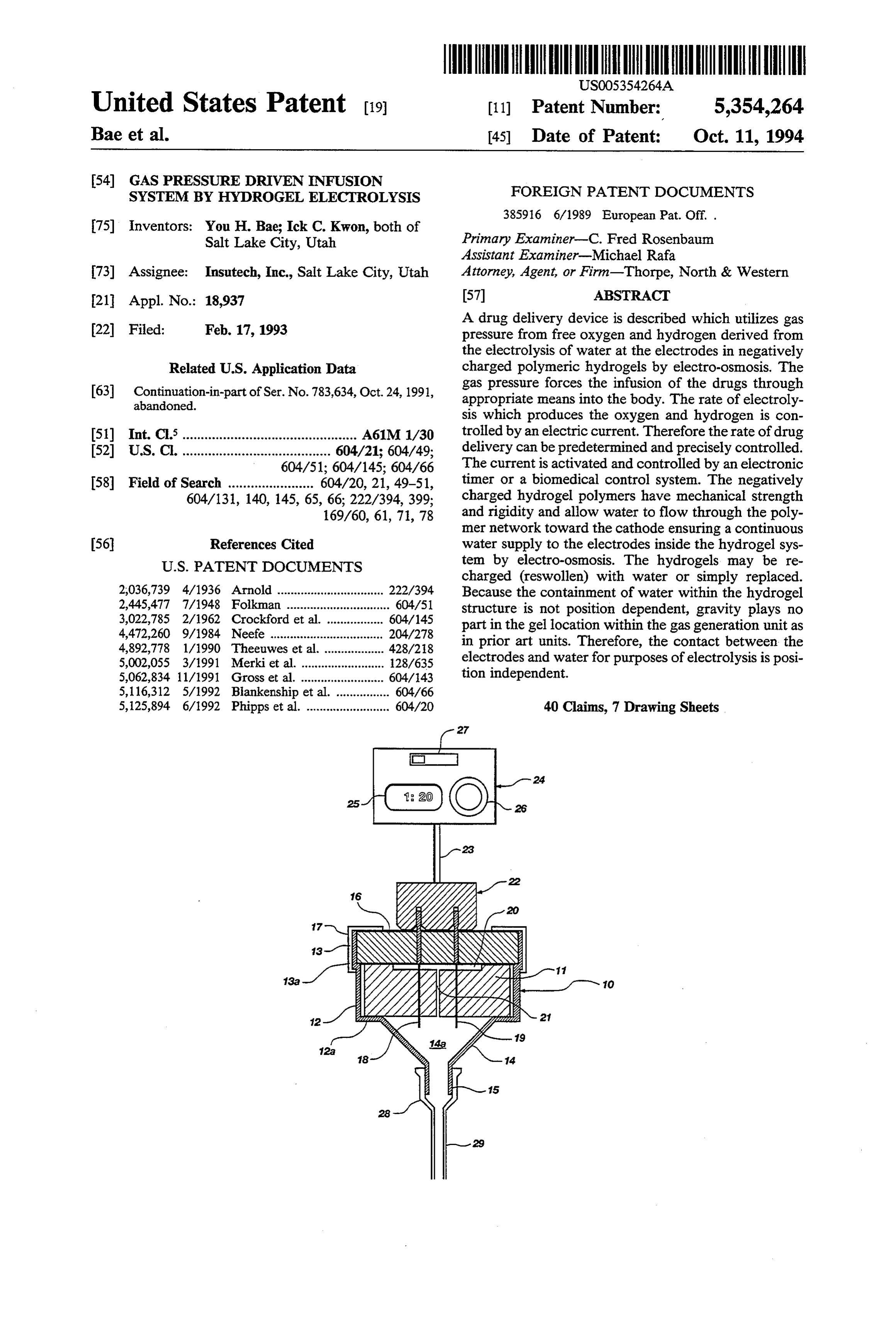
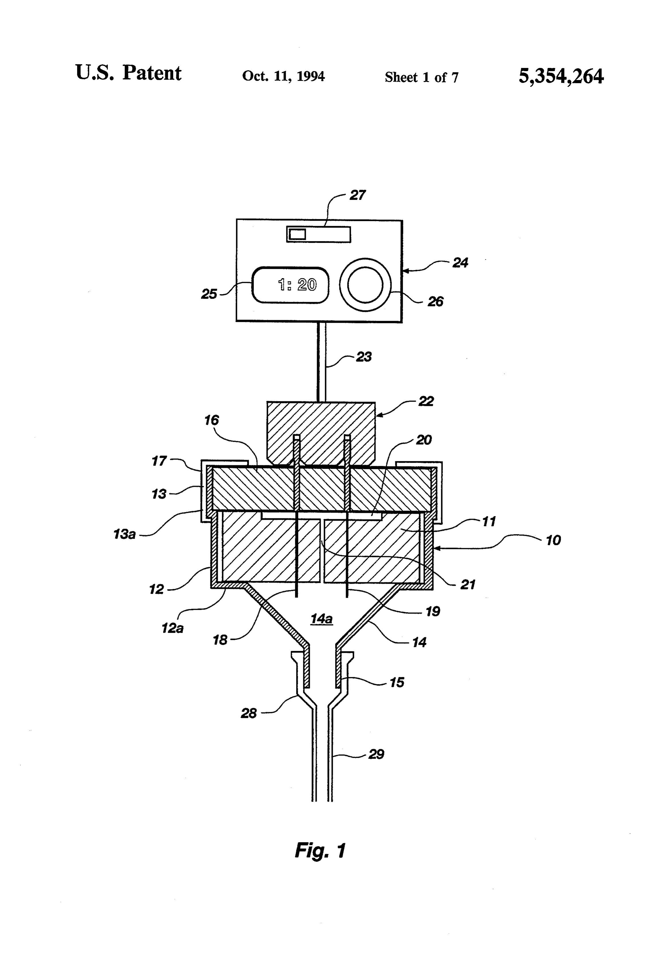
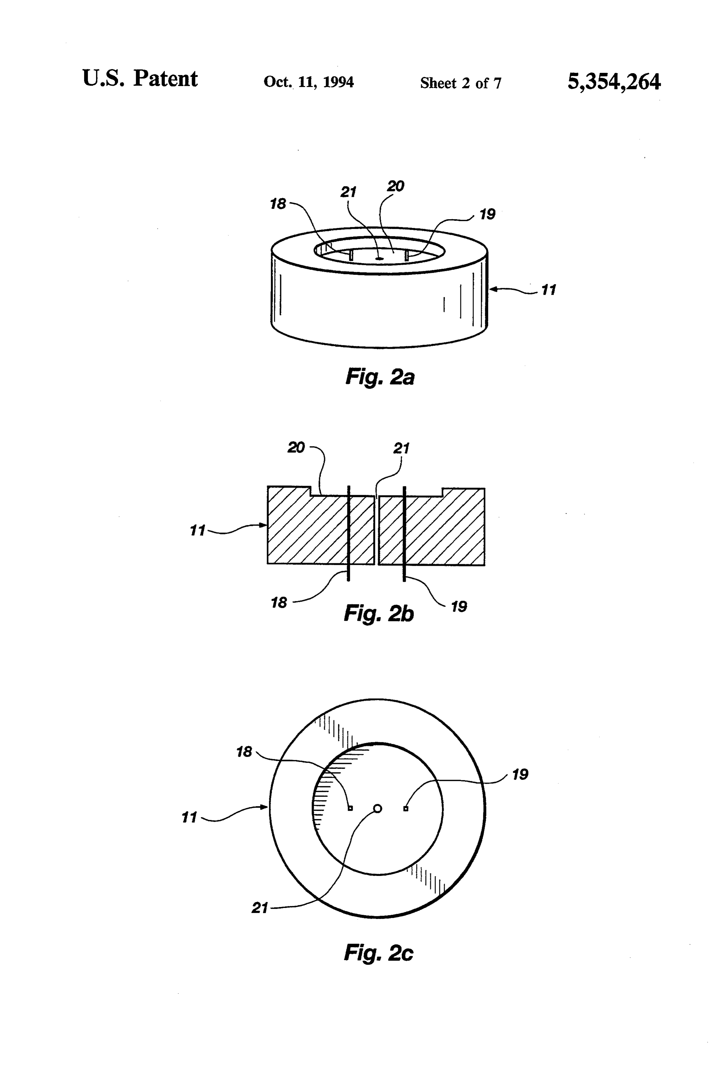
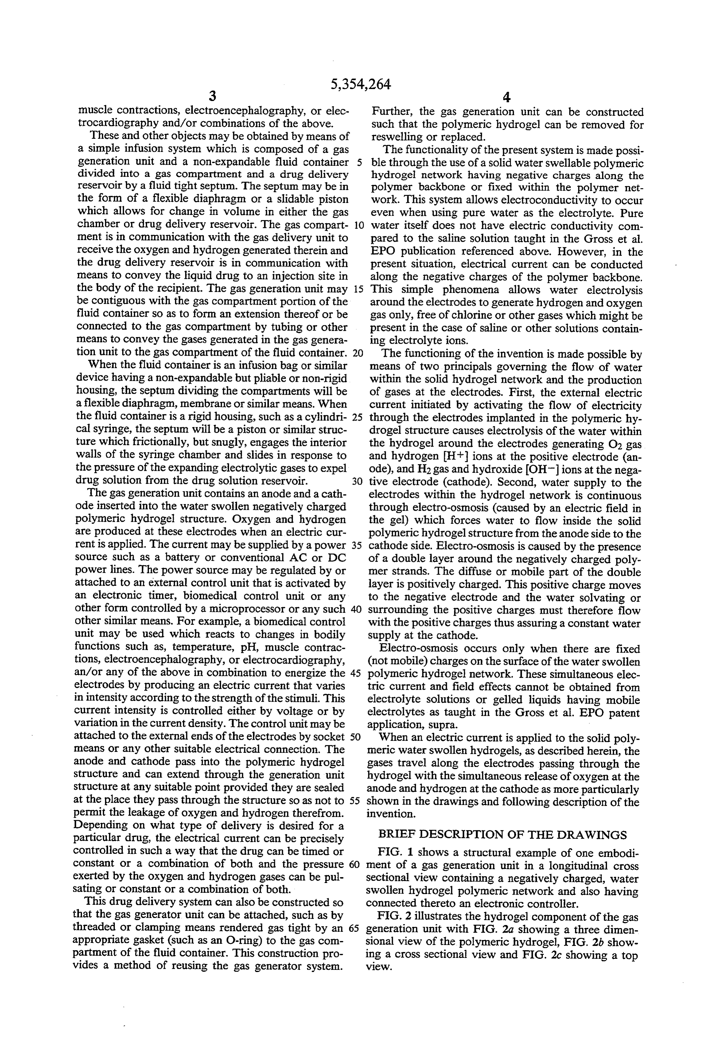
Depending on what type of delivery is desired for a particular drug, the electrical current can be precisely BRIEF DESCRIPTION OF THE DRAWINGS controlled in such a way that the drug can be timed or FIG. 1 shows a structural example of one embodi constant or a combination of both and the pressure 60 ment of a gas generation unit in a longitudinal cross exerted by the oxygen and hydrogen gases can be pull sectional view containing a negatively charged, water sating or constant or a combination of both. swollen hydrogel polymeric network and also having This drug delivery system can also be constructed so connected thereto an electronic controller. that the gas generator unit can be attached, such as by FIG. 2 illustrates the hydrogel component of the gas threaded or clamping means rendered gas tight by an 65 generation unit with FIG. 2a showing a three dimen appropriate gasket (such as an O-ring) to the gas con sional view of the polymeric hydrogel, FIG.2b show partment of the fluid container. This construction pro ing a cross sectional view and FIG.2c showing a top vides a method of reusing the gas generator system. VeW.
Page 11
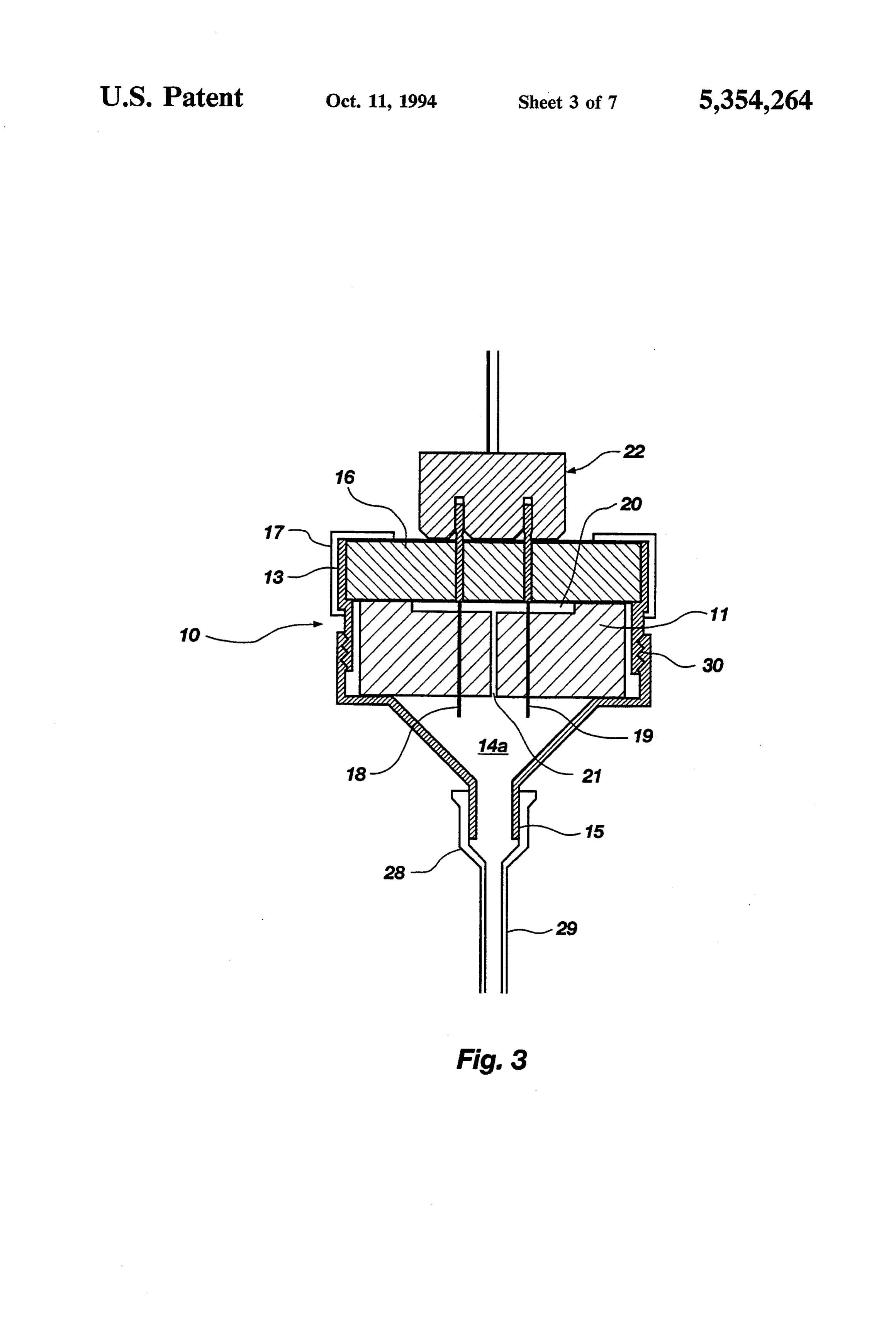
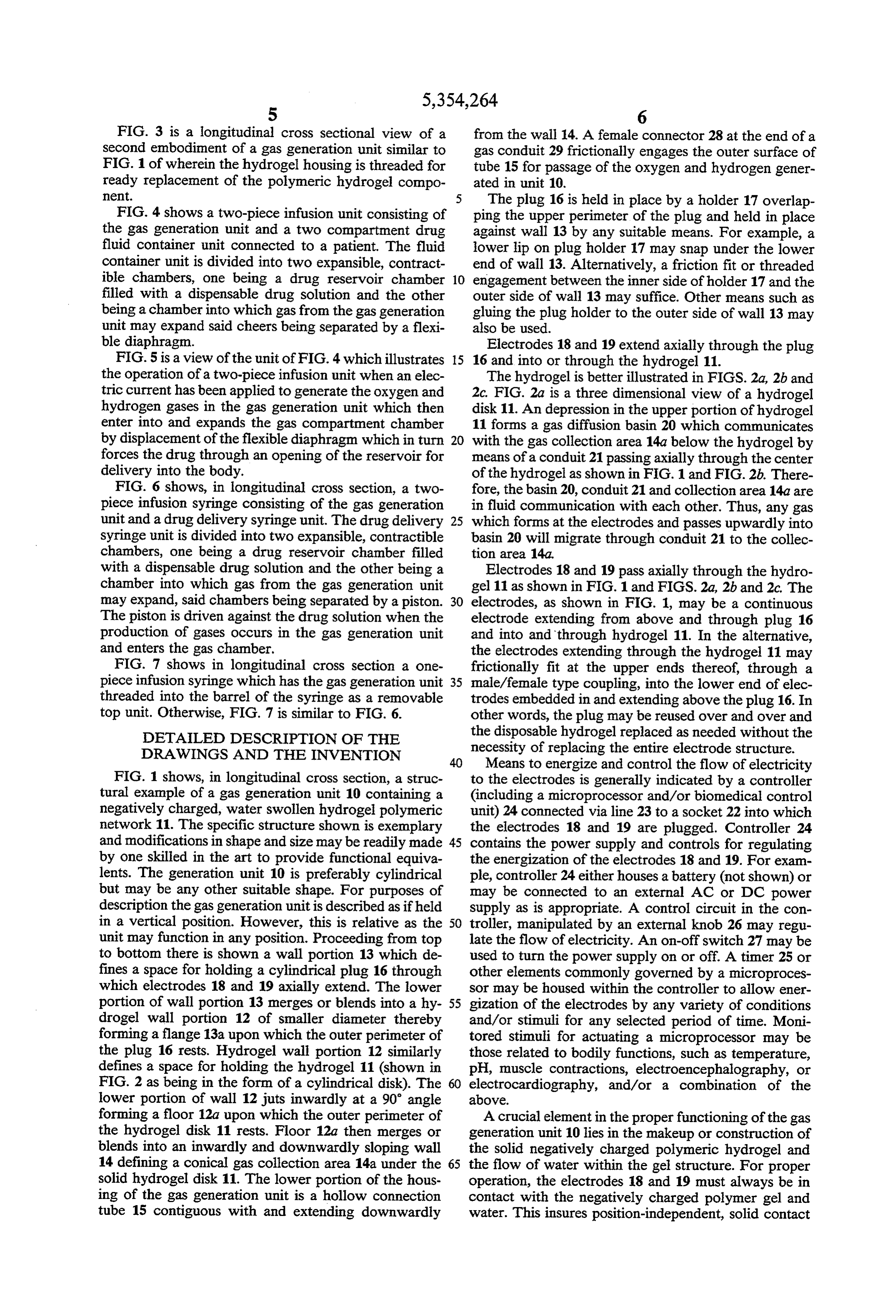
FIG. 3 is a longitudinal cross sectional view of a from the wall 14. A female connector 28 at the end of a second embodiment of a gas generation unit similar to gas conduit 29 frictionally engages the outer surface of FIG. 1 of wherein the hydrogel housing is threaded for tube 15 for passage of the oxygen and hydrogen gener ready replacement of the polymeric hydrogel compo ated in unit 10.
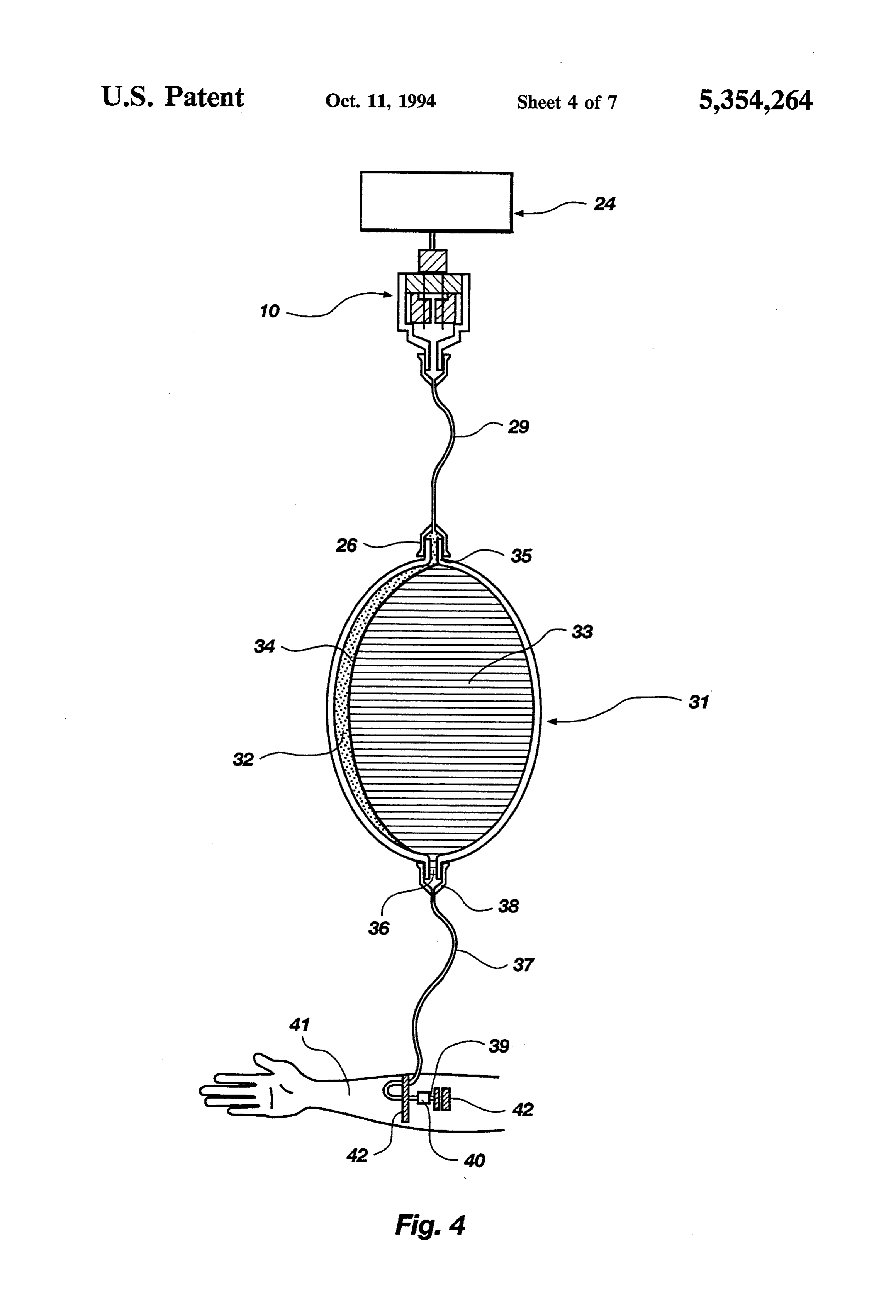
nent. 5 The plug 16 is held in place by a holder 17 overlap FIG. 4 shows a two-piece infusion unit consisting of ping the upper perimeter of the plug and held in place the gas generation unit and a two compartment drug against wall 13 by any suitable means. For example, a fluid container unit connected to a patient. The fluid lower lip on plug holder 17 may snap under the lower container unit is divided into two expansible, contract end of wall 13. Alternatively, a friction fit or threaded ible chambers, one being a drug reservoir chamber 10 engagement between the inner side of holder 17 and the filled with a dispensable drug solution and the other outer side of wall 13 may suffice. Other means such as being a chamber into which gas from the gas generation gluing the plug holder to the outer side of wall 13 may unit may expand said cheers being separated by a flexi also be used.
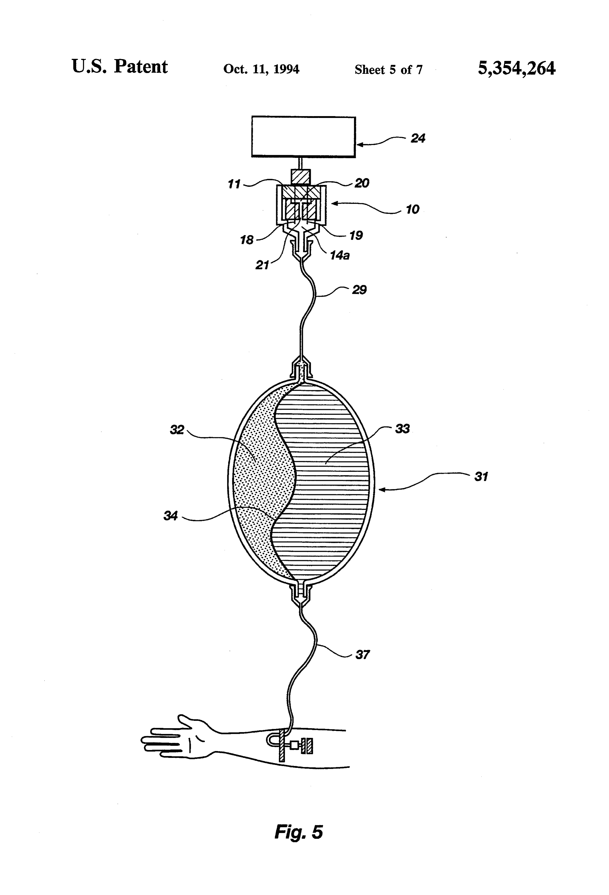
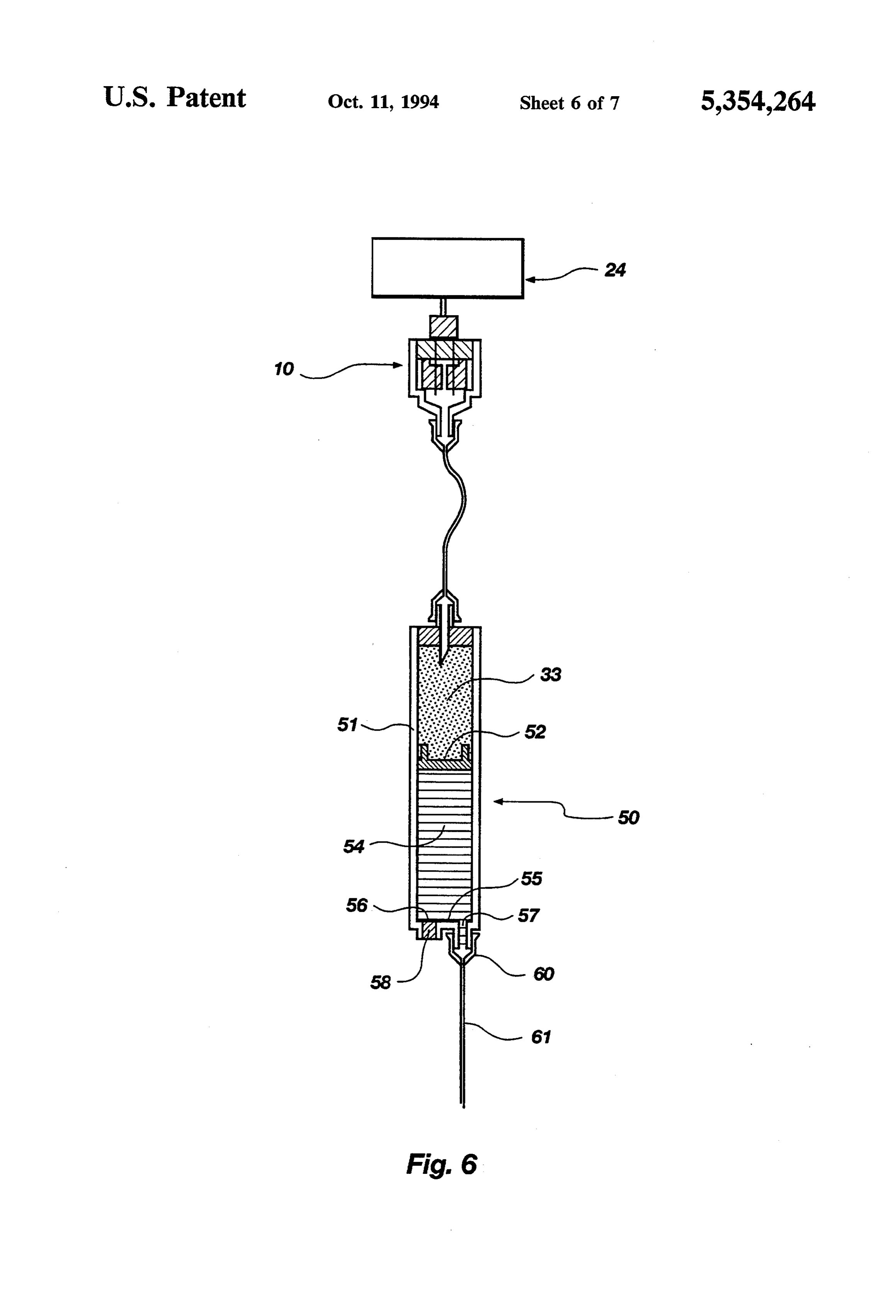
ble diaphragm. Electrodes 18 and 19 extend axially through the plug FIG. 5 is a view of the unit of FIG. 4 which illustrates 15 16 and into or through the hydrogel 11. the operation of a two-piece infusion unit when an elec The hydrogel is better illustrated in FIGS. 2a, 2b and tric current has been applied to generate the oxygen and 2c. FIG. 2a is a three dimensional view of a hydrogel hydrogen gases in the gas generation unit which then disk 11. An depression in the upper portion of hydrogel enter into and expands the gas compartment chamber 11 forms a gas diffusion basin 20 which communicates by displacement of the flexible diaphragm which in turn 20 with the gas collection area 14a below the hydrogel by forces the drug through an opening of the reservoir for means of a conduit 21 passing axially through the center delivery into the body. of the hydrogel as shown in FIG. 1 and FIG.2b. There FIG. 6 shows, in longitudinal cross section, a two fore, the basin 20, conduit 21 and collection area 14a are piece infusion syringe consisting of the gas generation in fluid communication with each other. Thus, any gas unit and a drug delivery syringe unit. The drug delivery 25 which forms at the electrodes and passes upwardly into syringe unit is divided into two expansible, contractible basin 20 will migrate through conduit 21 to the collec chambers, one being a drug reservoir chamber filled tion area 14a.
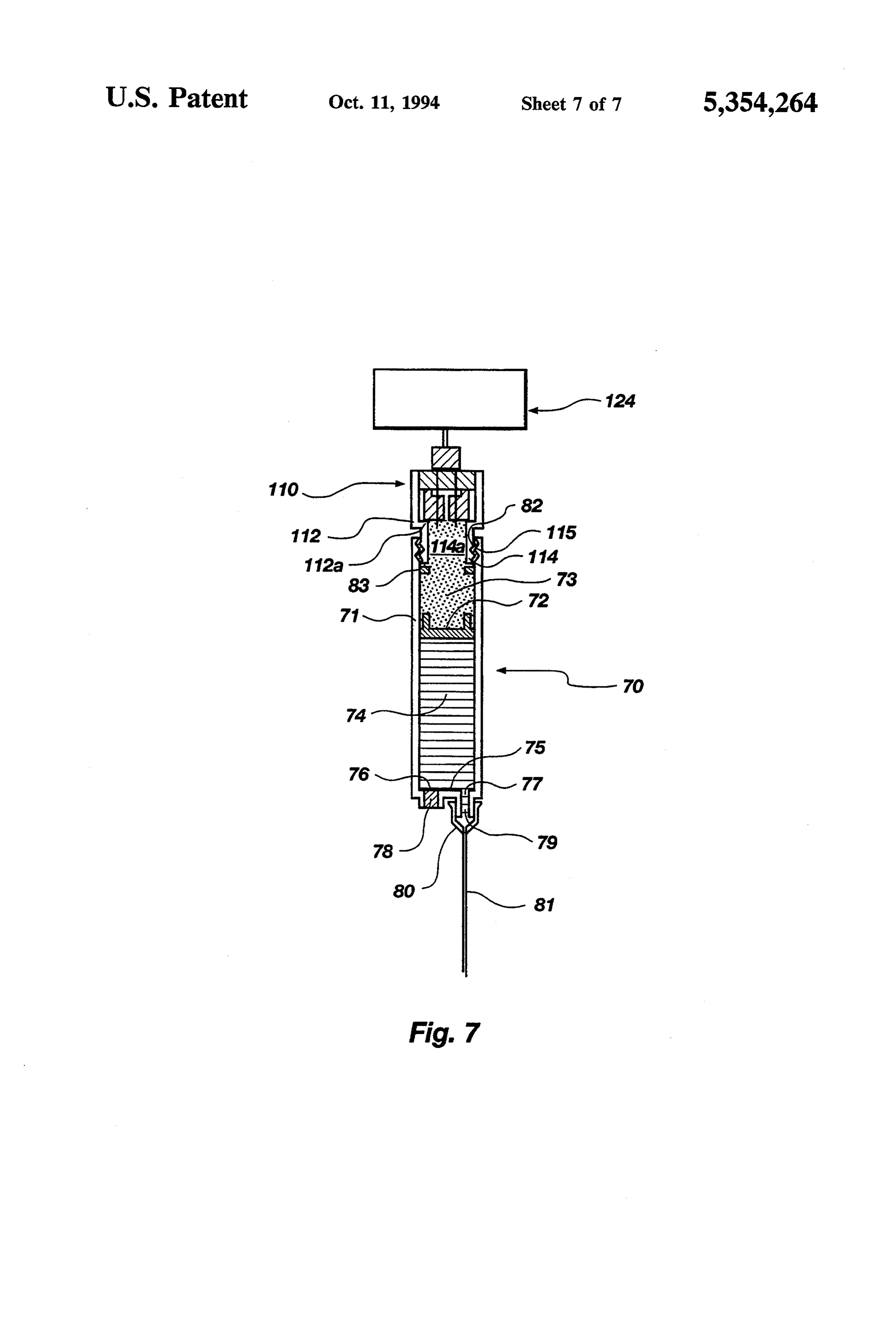
with a dispensable drug solution and the other being a Electrodes 18 and 19 pass axially through the hydro chamber into which gas from the gas generation unit gel 11 as shown in FIG. 1 and FIGS. 2a, 2b and 2c. The may expand, said chambers being separated by a piston. 30 electrodes, as shown in FIG. 1, may be a continuous The piston is driven against the drug solution when the electrode extending from above and through plug 16 production of gases occurs in the gas generation unit and into and through hydrogel 11. In the alternative, and enters the gas chamber. the electrodes extending through the hydrogel 11 may FIG. 7 shows in longitudinal cross section a one frictionally fit at the upper ends thereof, through a piece infusion syringe which has the gas generation unit 35 male/female type coupling, into the lower end of elec threaded into the barrel of the syringe as a removable trodes embedded in and extending above the plug 16. In top unit. Otherwise, FIG. 7 is similar to FIG. 6. other words, the plug may be reused over and over and DETAILED DESCRIPTION OF THE the disposable hydrogel replaced as needed without the DRAWINGS AND THE INVENTION necessity of replacing the entire electrode structure. Means to energize and control the flow of electricity
FIG. 1 shows, in longitudinal cross section, a struc to the electrodes is generally indicated by a controller tural example of a gas generation unit 10 containing a (including a microprocessor and/or biomedical control negatively charged, water swollen hydrogel polymeric unit) 24 connected via line 23 to a socket 22 into which network 11. The specific structure shown is exemplary the electrodes 18 and 19 are plugged. Controller 24 and modifications in shape and size may be readily made 45 contains the power supply and controls for regulating by one skilled in the art to provide functional equiva the energization of the electrodes 18 and 19. For exam lents. The generation unit 10 is preferably cylindrical ple, controller 24 eitherhouses a battery (not shown) or but may be any other suitable shape. For purposes of may be connected to an external AC or DC power description the gas generation unit is described as if held supply as is appropriate. A control circuit in the con in a vertical position. However, this is relative as the 50 troller, manipulated by an external knob 26 may regu unit may function in any position. Proceeding from top late the flow of electricity. An on-off switch 27 may be to bottom there is shown a wall portion 13 which de used to turn the power supply on or off. A timer 25 or fines a space for holding a cylindrical plug 16 through other elements commonly governed by a microproces which electrodes 18 and 19 axially extend. The lower sor may be housed within the controller to allow ener portion of wall portion 13 merges or blends into a hy 55 gization of the electrodes by any variety of conditions drogel wall portion 12 of smaller diameter thereby and/or stimuli for any selected period of time. Moni forming a flange 13a upon which the outer perimeter of tored stimuli for actuating a microprocessor may be the plug 16 rests. Hydrogel wall portion 12 similarly those related to bodily functions, such as temperature, defines a space for holding the hydrogel 11 (shown in pH, muscle contractions, electroencephalography, or FIG. 2 as being in the form of a cylindrical disk). The 60 electrocardiography, and/or a combination of the lower portion of wall 12 juts inwardly at a 90° angle above.
forming a floor 12a upon which the outer perimeter of A crucial element in the proper functioning of the gas the hydrogel disk 11 rests. Floor 12a then merges or generation unit 10 lies in the makeup or construction of blends into an inwardly and downwardly sloping wall the solid negatively charged polymeric hydrogel and 14 defining a conical gas collection area 14a under the 65 the flow of water within the gel structure. For proper solid hydrogel disk 11. The lower portion of the hous operation, the electrodes 18 and 19 must always be in ing of the gas generation unit is a hollow connection contact with the negatively charged polymer gel and tube 15 contiguous with and extending downwardly water. This insures position-independent, solid contact
Page 12
between electrodes and the water within the polymeric used. The electrodes 18 and 19 are composed of non hydrogel thereby producing gases at a constant rate sacrificial materials which conduct electric current and regardless of the position or direction of the gas genera are not decomposed by the electrolysis reaction, for tion unit. example gold, silver, copper, platinum and/or any of For this reason, the solid polymeric hydrogels must 5 the foregoing metal coated electrodes. The connector be synthesized from negatively charged polymer net 28 and tubing 29 may be composed of any suitable flexi works along polymer chains or from neutral polymer ble, nonporous material such as plasticized polyvinyl networks having entrapped therein linear polymers chloride, polyurethane, polyethylene, polypropylene, synthesized from negatively charged monomers or nat silicone rubber, etc.
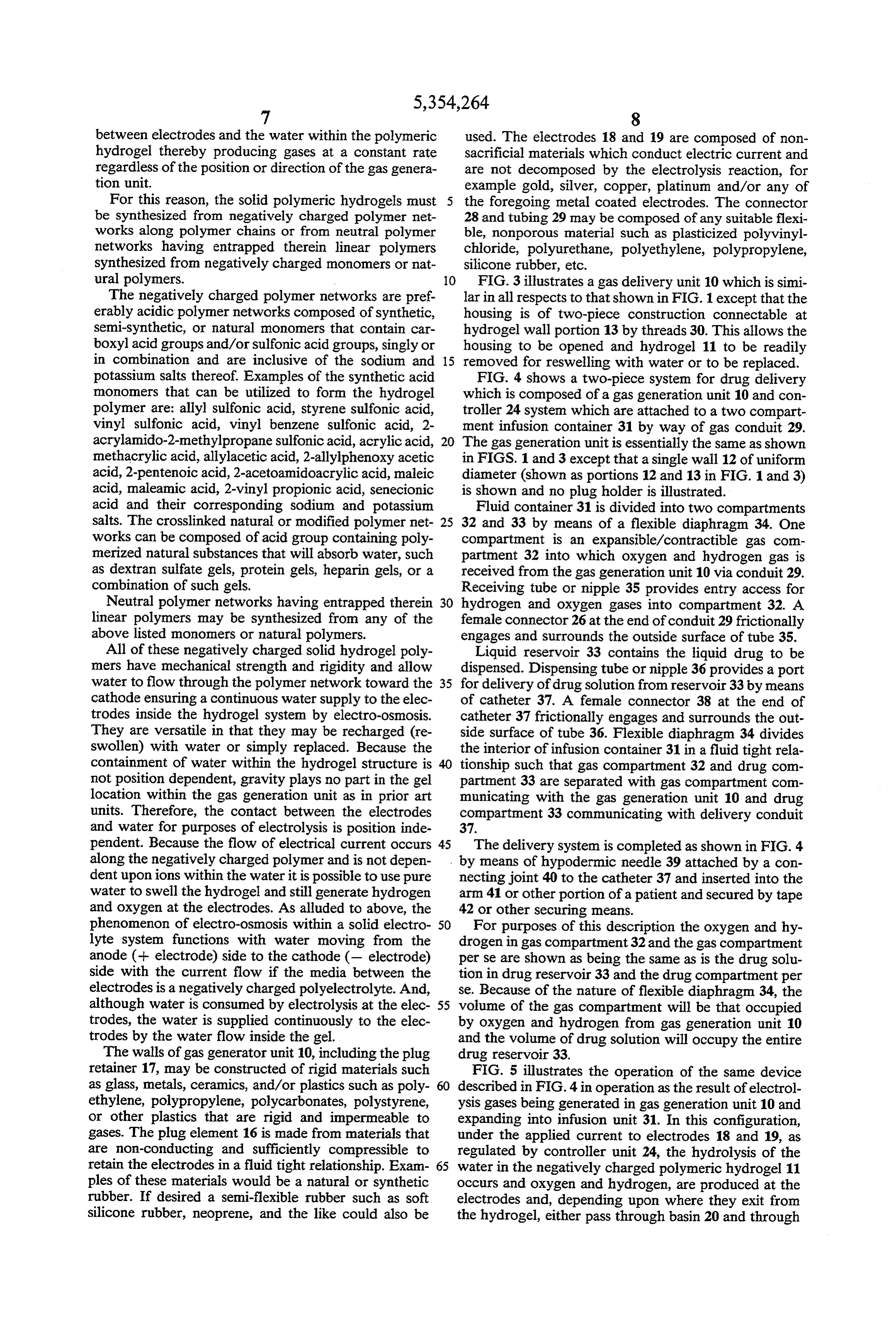
ural polymers. 10 FIG. 3 illustrates a gas delivery unit 10 which is simi The negatively charged polymer networks are pref lar in all respects to that shown in FIG. 1 except that the erably acidic polymer networks composed of synthetic, housing is of two-piece construction connectable at semi-synthetic, or natural monomers that contain car hydrogel wall portion 13 by threads 30. This allows the boxyl acid groups and/or sulfonic acid groups, singly or housing to be opened and hydrogel 11 to be readily in combination and are inclusive of the sodium and 15 removed for reswelling with water or to be replaced. potassium salts thereof. Examples of the synthetic acid FIG. 4 shows a two-piece system for drug delivery monomers that can be utilized to form the hydrogel which is composed of a gas generation unit 10 and con polymer are: allyl sulfonic acid, styrene sulfonic acid, troller 24 system which are attached to a two compart vinyl sulfonic acid, vinyl benzene sulfonic acid, 2 ment infusion container 31 by way of gas conduit 29. acrylamido-2-methylpropane sulfonic acid, acrylic acid, 20 The gas generation unit is essentially the same as shown methacrylic acid, allylacetic acid, 2-allylphenoxyacetic in FIGS. 1 and 3 except that a single wall 12 of uniform acid, 2-pentenoic acid, 2-acetoamidoacrylic acid, maleic diameter (shown as portions 12 and 13 in FIG. 1 and 3) acid, maleamic acid, 2-vinyl propionic acid, senecionic is shown and no plug holder is illustrated. acid and their corresponding sodium and potassium Fluid container 31 is divided into two compartments salts. The crosslinked natural or modified polymer net 25 32 and 33 by means of a flexible diaphragm 34. One works can be composed of acid group containing poly compartment is an expansible/contractible gas com merized natural substances that will absorb water, such partment 32 into which oxygen and hydrogen gas is as dextran sulfate gels, protein gels, heparin gels, or a received from the gas generation unit 10 via conduit 29. combination of such gels. Receiving tube or nipple 35 provides entry access for Neutral polymer networks having entrapped therein hydrogen and oxygen gases into compartment 32. A linear polymers may be synthesized from any of the female connector 26 at the end of conduit 29 frictionally above listed monomers or natural polymers. engages and surrounds the outside surface of tube 35. All of these negatively charged solid hydrogel poly Liquid reservoir 33 contains the liquid drug to be mers have mechanical strength and rigidity and allow dispensed. Dispensing tube or nipple 36 provides a port water to flow through the polymer network toward the 35 for delivery of drug solution from reservoir 33 by means cathode ensuring a continuous water supply to the elec of catheter 37. A female connector 38 at the end of trodes inside the hydrogel system by electro-osmosis. catheter 37 frictionally engages and surrounds the out They are versatile in that they may be recharged (re side surface of tube 36. Flexible diaphragm 34 divides swollen) with water or simply replaced. Because the the interior of infusion container 31 in a fluid tight rela containment of water within the hydrogel structure is tionship such that gas compartment 32 and drug com not position dependent, gravity plays no part in the gel partment 33 are separated with gas compartment com location within the gas generation unit as in prior art municating with the gas generation unit 10 and drug units. Therefore, the contact between the electrodes compartment 33 communicating with delivery conduit and water for purposes of electrolysis is position inde 37.
pendent. Because the flow of electrical current occurs 45 The delivery system is completed as shown in FIG. 4 along the negatively charged polymer and is not depen by means of hypodermic needle 39 attached by a con dent upon ions within the water it is possible to use pure necting joint 40 to the catheter 37 and inserted into the water to swell the hydrogel and still generate hydrogen arm 41 or other portion of a patient and secured by tape and oxygen at the electrodes. As alluded to above, the 42 or other securing means.
phenomenon of electro-osmosis within a solid electro 50 For purposes of this description the oxygen and hy lyte system functions with water moving from the drogen in gas compartment 32 and the gas compartment anode (-- electrode) side to the cathode (- electrode) perse are shown as being the same as is the drug solu side with the current flow if the media between the tion in drug reservoir 33 and the drug compartment per electrodes is a negatively charged polyelectrolyte. And, se. Because of the nature of flexible diaphragm 34, the although water is consumed by electrolysis at the elec 55 volume of the gas compartment will be that occupied trodes, the water is supplied continuously to the elec by oxygen and hydrogen from gas generation unit 10 trodes by the water flow inside the gel. and the volume of drug solution will occupy the entire The walls of gas generator unit 10, including the plug drug reservoir 33.
retainer 17, may be constructed of rigid materials such FIG. 5 illustrates the operation of the same device as glass, metals, ceramics, and/or plastics such as poly 60 described in FIG. 4 in operation as the result of electrol ethylene, polypropylene, polycarbonates, polystyrene, ysis gases being generated in gas generation unit 10 and or other plastics that are rigid and impermeable to expanding into infusion unit 31. In this configuration, gases. The plug element 16 is made from materials that under the applied current to electrodes 18 and 19, as are non-conducting and sufficiently compressible to regulated by controller unit 24, the hydrolysis of the retain the electrodes in a fluid tight relationship. Exam 65 water in the negatively charged polymeric hydrogel 11 ples of these materials would be a natural or synthetic occurs and oxygen and hydrogen, are produced at the rubber. If desired a semi-flexible rubber such as soft electrodes and, depending upon where they exit from silicone rubber, neoprene, and the like could also be the hydrogel, either pass through basin 20 and through
Page 13
conduit 21 to collection space 14a or are generated of the water in the negatively charged polymeric hy directly into collection space 14a. In either event, these drogel, which enter compartment 53 from the liquid gases pass from the gas generation unit 10, through the phase drug solution in reservoir 54. The piston 52 tubing 29 that connects the gas generator 10 with the moves in response to the pressure of the gases produced fluid container 31. The drug solution in drug compart by electrolysis occurring in the hydrogel. As shown in ment 33 is displaced by these gases as they expand into FIG. 6, the gas generation unit 10 and controller 24 are gas compartment 32. The pressure exerted by the ex the same as described for FIGS. 1-5 except for the panding gases in compartment 32 displaces flexible dia means by which the gases enter into gas compartment phragm 34 exerting pressure against drug solution in 53 from tubing 29. As shown in FIG. 6, a hollow needle reservoir 33 which then forces the drug solution 10 or tube 62, having a blunt proximal end and a sharpened through catheter 37 for delivery into the body through distal end, is engaged at the proximal end in female hypodermic needle 39. connector 36. The upper end of syringe 50 is sealed by The walls or housing of fluid container 31 is made of a plug 63. The plug 63 is pierced by the sharpened end any suitable non-expandable and impermeable materials of needle 62 to permit entry of electrolysis gases from that can be flexible or non-flexible such as glass, metals, 15 gas generation unit 10 via line 29. Plug 63 may be made ceramics, and/or plastics such as polyethylene, poly from materials as used for plug 16 in FIGS. 1-5, i.e. propylene, polycarbonates, polystyrene, polyvinylchlo materials that are sufficiently compressible to retain ride or other plastics. In other words, the wall of con needle or tube 62 in a fluid tight relationship. Examples tainer 31 must be non-expandable so as not to expand of these materials are natural or synthetic rubber and, if under the influence of the pressure of gas entering com 20 desired a semi-flexible rubber such as soft silicone rub partment 32 or upon the filling of reservoir 33 with a ber, neoprene could be used.
drug solution. However, the outer wall structure may FIG. 7 illustrates an embodiment of a syringe type be either flexible, deformable (pliable) or rigid depend device which is unitary with the gas generation unit. ing upon the circumstances of use. The diaphragm is There is shown a syringe 70 having a unitary, non flexible so as to form a displacable partition or septum 25 expandable cylindrical wall 71 defining a barrel which between compartment 32 and reservoir 33 and may be is divided into two expansible contractible compart made of any suitable impermeable material such as plas ments, gas compartment 73 and drug solution reservoir ticized polyvinyl chloride, polyethylene, polypropyl 74 by a piston 72. The floor or bottom 75 of the syringe ene, polyurethane, nylon and the like. Basically, any of contains two ports 76 and 77. Port 76 is used for filling the materials of a flexible nature used in making the 30 reservoir 74 with drug solution and is stopped with a container 31 may be used. When reservoir 33 is initially self-sealing material 78 that will seal itself after being filled with drug solution the fluid container volume will punctured with a needle, hollow wire or other filling be essentially that occupied by reservoir 33. However, means used for inserting the drug solution into reservoir when gases enter compartment 32, the diaphragm or 74. This filling port 76 allows the drug solution to be septum is displaced by the expanding of compartment 35 introduced into the syringe device 70 at any suitable 32 thereby forcing drug solution out of reservoir 33. time, i.e. prior to use, as a recharge during use or for When reservoir 33 has been emptied of the drug solu refilling following use. Any material which has self tion by means of the displacement of diaphragm 34, sealing ability after puncturing by sharp needle or other compartment 32 will occupy essentially all of the vol filling means can be used for sealing the filling port 76. ume of fluid container 31. Port 77 is further defined by a nipple or tube 79 extend FIG. 6 illustrates a syringe delivery device 50 having ing from floor 75. A connection joint 80 is friction fitted a gas generation unit 10 and controller 24 similar to that about nipple 79 and holds a needle or catheter line 81. shown in FIG. 4 wherein comparable elements in the Piston 72 frictionally engages the inner walls of barrel gas generation unit 10 and controller 24 are identified 71 in a fluid tight relationship and separates the gases, by the same numerals as in FIG. 4. The syringe device 45 which are produced by electrolysis of the water in the or fluid container 50 is shown as having a unitary, non hydrogel and which enter compartment 73, from the expandable cylindrical wall 51 defining a barrel which liquid phase drug solution in reservoir 74. The piston 72 is divided into two expansible contractible compart moves in response to the pressure of the gases produced ments, gas compartment 53 and drug solution reservoir by electrolysis occurring in the hydrogel. As shown in 54 by a piston 52. The floor or bottom 55 of the syringe 50 FIG. 7, the gas generation unit 110 and controller 124 contains two ports 56 and 57. Port 56 is used for filling are similar in nature and function to gas generation unit reservoir 54 with drug solution and is stopped with a 10 and controller 24 in FIGS. 1-6. However, in this self-sealing material 58 that will seal itself after being embodiment, the gas generation unit 110 is contiguous punctured with a needle, hollow wire or other filling with and forms an extension of syringe 70. The upper means used for inserting the drug solution into reservoir 55 end of syringe 70 is adapted to receive the gas genera 54. This filling port 56 allows the drug solution to be tion unit 110. In that regard, the inner end portion of introduced into reservoir of the syringe device 50 at any cylindrical wall 71 bears threads 82. Also a gasket 83 or suitable time, i.e. prior to use, as a recharge during use similar stopper type means may be secured to the inner or for refilling following use. Any material which has surface of wall 71 just below the threads 82 to prevent self-sealing ability after puncturing by sharp needle or the piston 72 from moving beyond means 83 during the other filling means can be used for sealing the filling process of filling the syringe with drug solution and port 56. Port 57 is further defined by a nipple or tube 59 may also serve to engage and seal the bottom end of the extending downwardly from floor 55. A connection gas generation unit as will be described. joint 60 is friction fitted about nipple 59 and holds a Gas generation unit 110 has a cylindrical housing hypodermic needle or catheter line 61. 65 wall 112 defining a space for holding a hydrogel disk Piston 52 frictionally engages the inner walls of barrel 111 and a closing plug 116. The lower portion of wall 51 in a fluid tight relationship and separates the hydro 112 merges or blends inwardly at a 90° angle forming a gen and oxygen gases, that are produced by electrolysis floor 1.12a upon which the outer perimeter of the hy
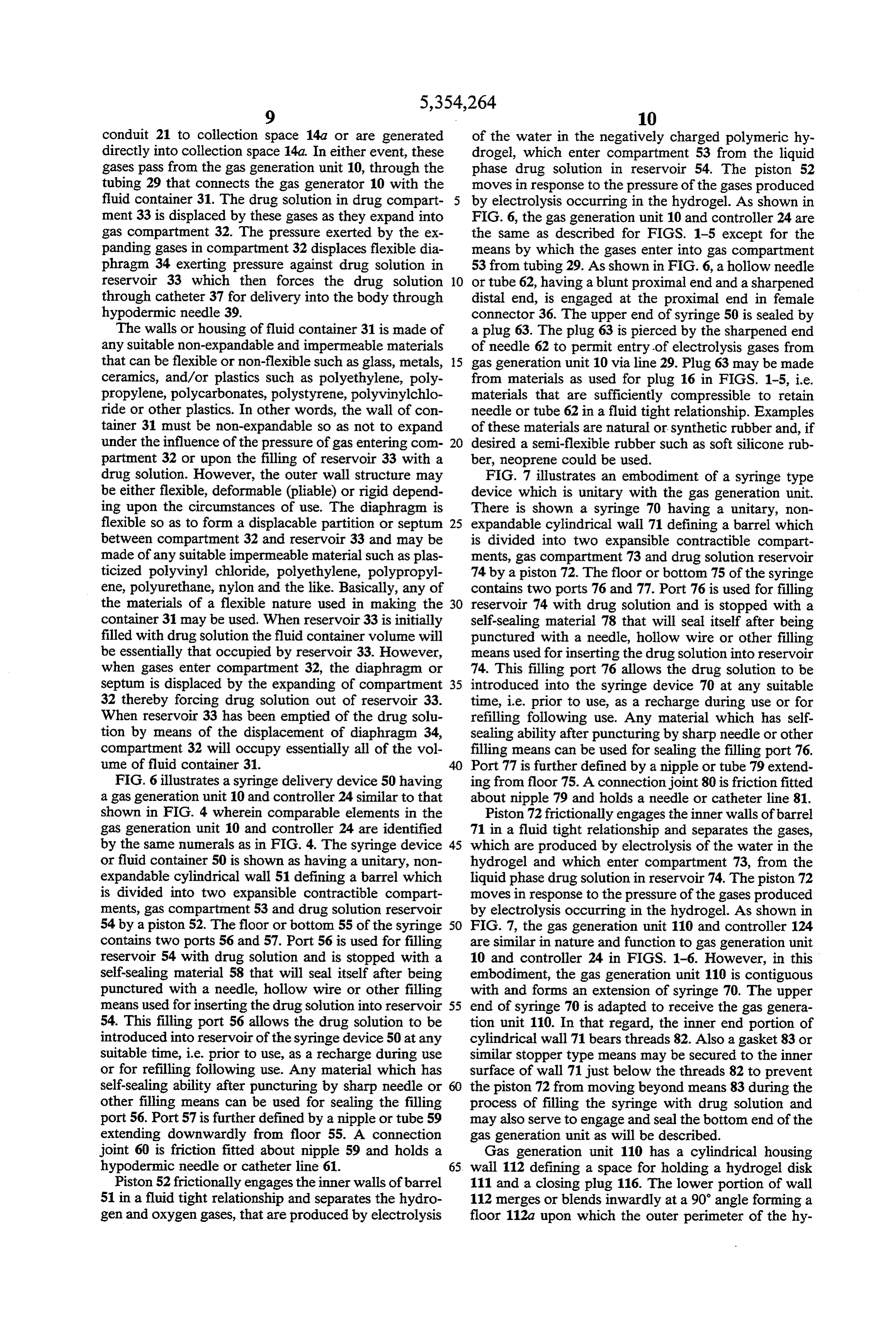
Page 14
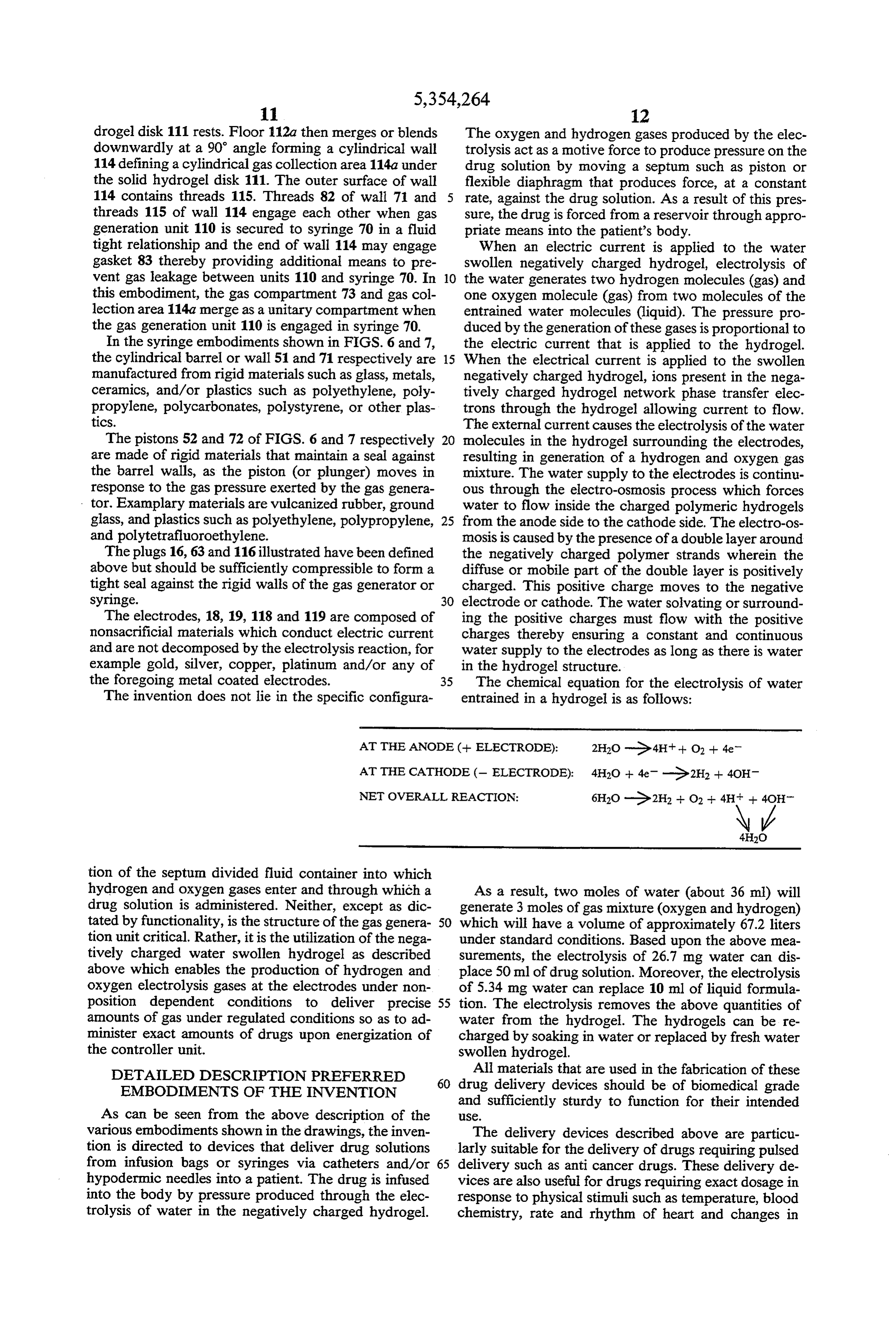
drogel disk 111 rests. Floor 112a then merges or blends The oxygen and hydrogen gases produced by the elec downwardly at a 90° angle forming a cylindrical wall trolysis act as a motive force to produce pressure on the 114 defining a cylindrical gas collection area 114a under drug solution by moving a septum such as piston or the solid hydrogel disk 111. The outer surface of wall flexible diaphragm that produces force, at a constant 114 contains threads 115. Threads 82 of wall 71 and rate, against the drug solution. As a result of this pres threads 115 of wall 114 engage each other when gas sure, the drug is forced from a reservoir through appro generation unit 110 is secured to syringe 70 in a fluid priate means into the patient's body. tight relationship and the end of wall 114 may engage When an electric current is applied to the water gasket 83 thereby providing additional means to pre swollen negatively charged hydrogel, electrolysis of vent gas leakage between units 110 and syringe 70. In 10 the water generates two hydrogen molecules (gas) and this embodiment, the gas compartment 73 and gas col one oxygen molecule (gas) from two molecules of the lection area 114a merge as a unitary compartment when entrained water molecules (liquid). The pressure pro the gas generation unit 110 is engaged in Syringe 70. duced by the generation of these gases is proportional to In the syringe embodiments shown in FIGS. 6 and 7, the electric current that is applied to the hydrogel. the cylindrical barrel or wall 51 and 71 respectively are 15 When the electrical current is applied to the swollen manufactured from rigid materials such as glass, metals, negatively charged hydrogel, ions present in the nega ceramics, and/or plastics such as polyethylene, poly tively charged hydrogel network phase transfer elec propylene, polycarbonates, polystyrene, or other plas trons through the hydrogel allowing current to flow. tics. The external current causes the electrolysis of the water The pistons 52 and 72 of FIGS. 6 and 7 respectively molecules in the hydrogel surrounding the electrodes, are made of rigid materials that maintain a seal against resulting in generation of a hydrogen and oxygen gas the barrel walls, as the piston (or plunger) moves in mixture. The water supply to the electrodes is continu response to the gas pressure exerted by the gas genera ous through the electro-osmosis process which forces tor. Examplary materials are vulcanized rubber, ground water to flow inside the charged polymeric hydrogels glass, and plastics such as polyethylene, polypropylene, 25 from the anode side to the cathode side. The electro-os and polytetrafluoroethylene. mosis is caused by the presence of a double layer around The plugs 16, 63 and 116 illustrated have been defined the negatively charged polymer strands wherein the above but should be sufficiently compressible to form a diffuse or mobile part of the double layer is positively tight seal against the rigid walls of the gas generator or charged. This positive charge moves to the negative syringe. 30 electrode or cathode. The water solvating or surround The electrodes, 18, 19, 118 and 119 are composed of ing the positive charges must flow with the positive nonsacrificial materials which conduct electric current charges thereby ensuring a constant and continuous and are not decomposed by the electrolysis reaction, for water supply to the electrodes as long as there is water example gold, silver, copper, platinum and/or any of in the hydrogel structure.
the foregoing metal coated electrodes. 35 The chemical equation for the electrolysis of water The invention does not lie in the specific configura entrained in a hydrogel is as follows:
AT THE ANODE (+ ELECTRODE):
AT THE CATHODE (- ELECTRODE):
NET OVERALL REACTION:
tion of the septum divided fluid container into which hydrogen and oxygen gases enter and through which a As a result, two moles of water (about 36 ml) will drug solution is administered. Neither, except as dic generate 3 moles of gas mixture (oxygen and hydrogen) tated by functionality, is the structure of the gas genera 50 which will have a volume of approximately 67.2 liters tion unit critical. Rather, it is the utilization of the nega under standard conditions. Based upon the above mea tively charged water swollen hydrogel as described surements, the electrolysis of 26.7 mg water can dis above which enables the production of hydrogen and place 50 ml of drug solution. Moreover, the electrolysis oxygen electrolysis gases at the electrodes under non of 5.34 mg water can replace 10 ml of liquid formula position dependent conditions to deliver precise 55 tion. The electrolysis removes the above quantities of amounts of gas under regulated conditions so as to ad water from the hydrogel. The hydrogels can be re minister exact amounts of drugs upon energization of charged by soaking in water or replaced by fresh water the controller unit. swollen hydrogel.
DETALED DESCRIPTION PREFERRED All materials that are used in the fabrication of these 60 drug delivery devices should be of biomedical grade
EMBODIMENTS OF THE INVENTION
and sufficiently sturdy to function for their intended
As can be seen from the above description of the Se.
various embodiments shown in the drawings, the inven The delivery devices described above are particu tion is directed to devices that deliver drug solutions larly suitable for the delivery of drugs requiring pulsed from infusion bags or syringes via catheters and/or 65 delivery such as anti cancer drugs. These delivery de hypodermic needles into a patient. The drug is infused vices are also useful for drugs requiring exact dosage in into the body by pressure produced through the elec response to physical stimuli such as temperature, blood trolysis of water in the negatively charged hydrogel. chemistry, rate and rhythm of heart and changes in
Page 15
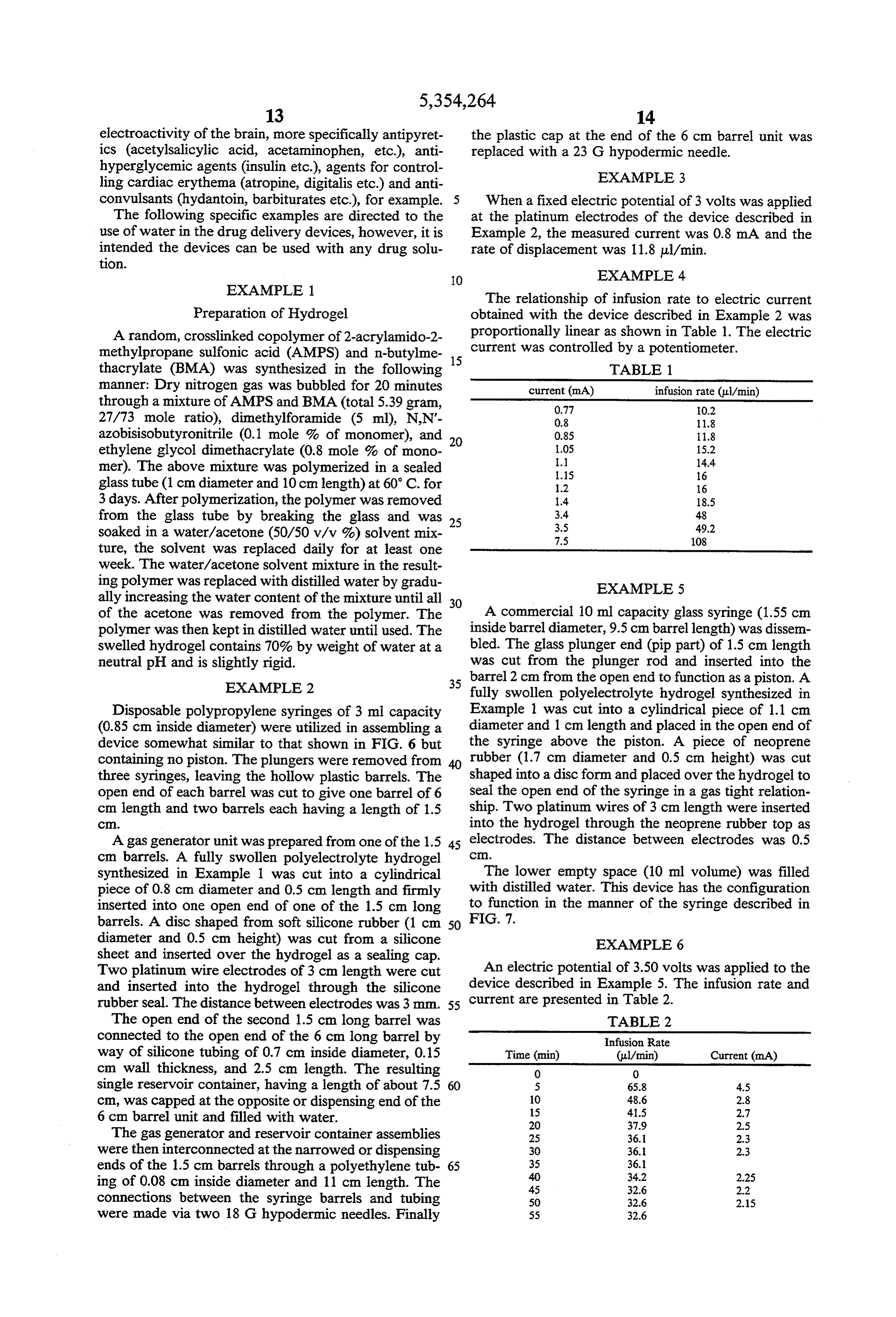
electroactivity of the brain, more specifically antipyret the plastic cap at the end of the 6 cm barrel unit was ics (acetylsalicylic acid, acetaminophen, etc.), anti replaced with a 23 G hypodermic needle. hyperglycemic agents (insulin etc.), agents for control EXAMPLE 3 ling cardiac erythema (atropine, digitalis etc.) and anti convulsants (hydantoin, barbiturates etc.), for example. When a fixed electric potential of 3 volts was applied The following specific examples are directed to the at the platinum electrodes of the device described in use of water in the drug delivery devices, however, it is Example 2, the measured current was 0.8 mA and the intended the devices can be used with any drug solu rate of displacement was 11.8 ul/min. tion.
EXAMPLE 1.
The relationship of infusion rate to electric current
Preparation of Hydrogel obtained with the device described in Example 2 was A random, crosslinked copolymer of 2-acrylamido-2- proportionally linear as shown in Table 1. The electric methylpropane sulfonic acid (AMPS) and n-butylme current was controlled by a potentiometer. thacrylate (BMA) was synthesized in the following 15 TABLE 1. manner: Dry nitrogen gas was bubbled for 20 minutes current (mA) infusion rate (ui/min) through a mixture of AMPS and BMA (total 5.39 gram, 0.77 0.2 27/73 mole ratio), dimethylforamide (5 ml), N,N'- 0.8 11.8 azobisisobutyronitrile (0.1 mole % of monomer), and 0.85 11.8 ethylene glycol dimethacrylate (0.8 mole % of mono 20 1.05
mer). The above mixture was polymerized in a sealed 1.15 16 glass tube (1 cm diameter and 10 cm length) at 60° C. for 1.2 16 3 days. After polymerization, the polymer was removed 1.4 18.5 from the glass tube by breaking the glass and was 25 3.4
soaked in a water/acetone (50/50 v/v 9%) solvent mix 7.5 108 ture, the solvent was replaced daily for at least one week. The water/acetone solvent mixture in the result ing polymer was replaced with distilled water by gradu EXAMPLE 5 ally increasing the water content of the mixture until all 30 of the acetone was removed from the polymer. The A commercial 10 ml capacity glass syringe (1.55 cm polymer was then kept in distilled water until used. The inside barrel diameter, 9.5 cm barrellength) was dissen swelled hydrogel contains 70% by weight of water at a bled. The glass plunger end (pip part) of 1.5 cm length neutral pH and is slightly rigid. was cut from the plunger rod and inserted into the EXAMPLE 2 35 barrel 2 cm from the open end to function as a piston. A fully swollen polyelectrolyte hydrogel synthesized in
Disposable polypropylene syringes of 3 ml capacity Example 1 was cut into a cylindrical piece of 1.1 cm (0.85 cm inside diameter) were utilized in assembling a diameter and 1 cm length and placed in the open end of device somewhat similar to that shown in FIG. 6 but the syringe above the piston. A piece of neoprene containing no piston. The plungers were removed from rubber (1.7 cm diameter and 0.5 cm height) was cut three syringes, leaving the hollow plastic barrels. The shaped into a disc form and placed over the hydrogel to open end of each barrel was cut to give one barrel of 6 seal the open end of the syringe in a gas tight relation cm length and two barrels each having a length of 1.5 ship. Two platinum wires of 3 cm length were inserted C. into the hydrogel through the neoprene rubber top as A gas generator unit was prepared from one of the 1.5 45 electrodes. The distance between electrodes was 0.5 cm barrels. A fully swollen polyelectrolyte hydrogel C.
synthesized in Example 1 was cut into a cylindrical The lower empty space (10 ml volume) was filled piece of 0.8 cm diameter and 0.5 cm length and firmly with distilled water. This device has the configuration inserted into one open end of one of the 1.5 cm long to function in the manner of the syringe described in barrels. A disc shaped from soft silicone rubber (1 cm 50 FIG. 7.
diameter and 0.5 cm height) was cut from a silicone EXAMPLE 6 sheet and inserted over the hydrogel as a sealing cap.
Two platinum wire electrodes of 3 cm length were cut An electric potential of 3.50 volts was applied to the and inserted into the hydrogel through the silicone device described in Example 5. The infusion rate and rubber seal. The distance between electrodes was 3 mm. 55 current are presented in Table 2. The open end of the second 1.5 cm long barrel was TABLE 2 connected to the open end of the 6 cm long barrel by Infusion Rate way of silicone tubing of 0.7 cm inside diameter, 0.15 Time (min) (ul/min) Current (mA) cm wall thickness, and 2.5 cm length. The resulting O O single reservoir container, having a length of about 7.5 60 5 65.8 4.5 cm, was capped at the opposite or dispensing end of the 10
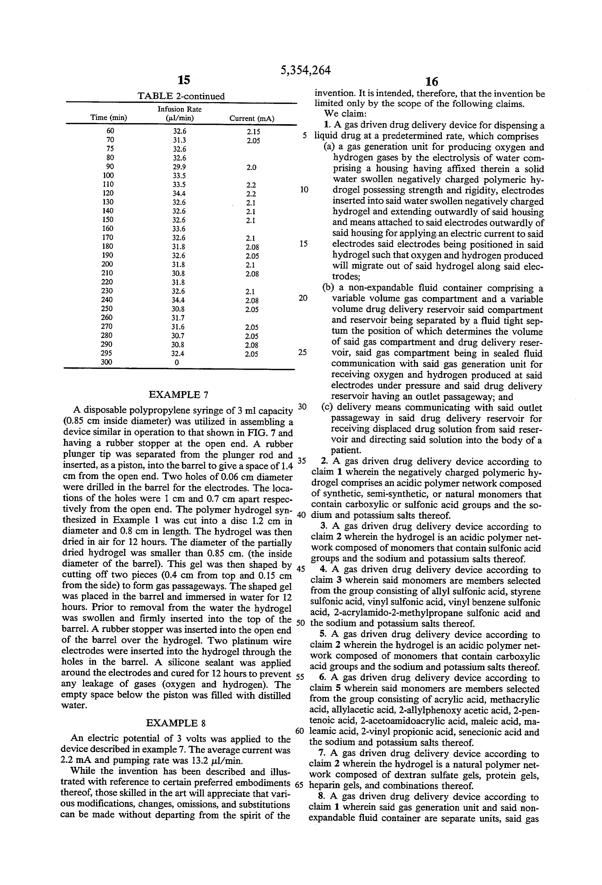
6 cm barrel unit and filled with water. 20 37.9 2.5 The gas generator and reservoir container assemblies 25 36.1 2.3 were then interconnected at the narrowed or dispensing 30 36.1 2.3 ends of the 1.5 cm barrels through a polyethylene tub 65 35
ing of 0.08 cm inside diameter and 11 cm length. The 45 32.6 2.2 connections between the syringe barrels and tubing 50 32.6 2.15 were made via two 18 G hypodermic needles. Finally 55 32.6
Page 16
TABLE 2-continued invention. It is intended, therefore, that the invention be Infusion Rate limited only by the scope of the following claims.
Time (min) (ul/min) Current (mA) We claim:
1. A gas driven drug delivery device for dispensing a 70 31.3 2.05 5 liquid drug at a predetermined rate, which comprises 75 32.6 (a) a gas generation unit for producing oxygen and 80 32.6 hydrogen gases by the electrolysis of water com
2.0 prising a housing having affixed therein a solid
water swollen negatively charged polymeric hy 120 34.4 2.2 drogel possessing strength and rigidity, electrodes 130 32.6 2.1 inserted into said water swollen negatively charged
hydrogel and extending outwardly of said housing 160 33.6 and means attached to said electrodes outwardly of 70 32.6 2.1 15 said housing for applying an electric current to said 180 31.8 2.08 electrodes said electrodes being positioned in said 190 32.6 2.05 hydrogel such that oxygen and hydrogen produced
will migrate out of said hydrogel along said elec 220 31.8 trodes;
230 32.6 2.1 (b) a non-expandable fluid container comprising a 240 34.4 2.08 2O variable volume gas compartment and a variable
2.05 volume drug delivery reservoir said compartment
and reservoir being separated by a fluid tight sep 280 30.7 2.05 turn the position of which determines the volume 290 30.8 2.08 of said gas compartment and drug delivery reser 295 32.4 2.05 25 voir, said gas compartment being in sealed fluid 300 0 communication with said gas generation unit for receiving oxygen and hydrogen produced at said electrodes under pressure and said drug delivery
EXAMPLE 7 reservoir having an outlet passageway; and
A disposable polypropylene syringe of 3 ml capacity 3O (c) delivery means communicating with said outlet (0.85 cm inside diameter) was utilized in assembling a passageway in said drug delivery reservoir for device similar in operation to that shown in FIG. 7 and receiving displaced drug solution from said reser having a rubber stopper at the open end. A rubber voir and directing said solution into the body of a plunger tip was separated from the plunger rod and 3.5 patient.
inserted, as a piston, into the barrel to give a space of 1.4 claimA1 gas 2. driven drug delivery device according to cm from the open end. Two holes of 0.06 cm diameter drogel comprisesthe wherein negatively charged polymeric hy an acidic polymer network composed were drilled in the barrel for the electrodes. The loca tions of the holes were 1 cm and 0.7 cm apart respec contain of synthetic, semi-synthetic, or natural monomers that tively from the open end. The polymer hydrogel syn dium carboxylic or sulfonic acid groups and the so thesized in Example 1 was cut into a disc 1.2 cm in and potassium salts thereof. diameter and 0.8 cm in length. The hydrogel was then claim 3. A gas driven drug delivery device according to dried in air for 12 hours. The diameter of the partially work composed 2 wherein the hydrogel is an acidic polymer net dried hydrogel was smaller than 0.85 cm. (the inside groups and the sodium of monomers that contain sulfonic acid diameter of the barrel). This gel was then shaped by 45 4. A gas driven drugand potassium salts thereof. delivery device according to cutting off two pieces (0.4 cm from top and 0.15 cm claim 3 wherein said monomers from the side) to form gas passageways. The shaped gel from the group consisting of allylare members selected sulfonic acid, styrene was placed in the barrel and immersed in water for 12 sulfonic acid, vinyl sulfonic acid, vinyl benzene sulfonic hours. Prior to removal from the water the hydrogel acid, 2-acrylamido-2-methylpropane sulfonic acid and was swollen and firmly inserted into the top of the 5O the sodium and potassium salts thereof. barrel. A rubber stopper was inserted into the open end 5. A gas driven drug delivery device according to of the barrel over the hydrogel. Two platinum wire claim electrodes were inserted into the hydrogel through the work 2composed wherein the hydrogel is an acidic polymer net of monomers that contain carboxylic holes in the barrel. A silicone sealant was applied acid groups and the sodium and potassium salts thereof. around the electrodes and cured for 12 hours to prevent 5 5 6. A gas driven drug delivery device according to any leakage of gases (oxygen and hydrogen). The claim 5 wherein said monomers are members selected empty space below the piston was filled with distilled from the group consisting of acrylic acid, methacrylic Water.
acid, allylacetic acid, 2-allylphenoxyacetic acid, 2-pen
EXAMPLE 8 tenoic acid, 2-acetoamidoacrylic acid, maleic acid, ma 6O leamic acid, 2-vinyl propionic acid, senecionic acid and
An electric potential of 3 volts was applied to the device described in example 7. The average current was the7.sodium and potassium salts thereof. A gas driven drug delivery device according to 2.2 mA and pumping rate was 13.2 ul/min. claim 2 wherein the hydrogel is a natural polymer net While the invention has been described and illus work composed of dextran sulfate gels, protein gels, trated with reference to certain preferred embodiments 65 heparingels, and combinations thereof. thereof, those skilled in the art will appreciate that vari 8. A gas driven drug delivery device according to ous modifications, changes, omissions, and substitutions claim 1 wherein said gas generation unit and said non can be made without departing from the spirit of the expandable fluid container are separate units, said gas
Page 17
generation unit having an outlet passageway in said ture through said disk permitting passage of such gases housing and said gas compartment having an inlet pas from said depression to said gas chamber in said fluid sageway, said passageways being interconnected in a container.
fluid tight relationship by conduit means for conveying 21. A method for the controlled delivery of a drug to oxygen and hydrogen produced as said electrodes to 5 a patient, which comprises;
said gas compartment under pressure. (1) providing an delivery system comprising: 9. A gas driven drug delivery device according to (a) a gas generation unit for producing oxygen and claim 8 wherein said fluid tight septum separating said hydrogen gases by the electrolysis of water com gas compartment from said drug delivery reservoir is a prising a housing having affixed therein a solid diaphragm. O water swollen negatively charged polymeric 10. A gas driven drug delivery device according to hydrogel possessing strength and rigidity, elec claim 9 wherein said fluid container is constructed of trodes inserted into said water swollen nega non-expandable, pliable material. tively charged hydrogel and extending out 11. A gas driven drug delivery device according to wardly of said housing and means attached to claim 8 wherein said fluid container is constructed of 15 said electrodes outwardly of said housing for rigid materials providing a gas compartment and liquid applying an electric current to said electrodes drug reservoir of uniform diameter and wherein said said electrodes being positioned in said hydrogel fluid tight septum separating said gas compartment such that oxygen and hydrogen produced will from said drug delivery reservoir is a piston. migrate out of said hydrogel along said elec 12. A gas driven drug delivery device according to 20 trodes;
claim 1 wherein said fluid container is constructed of rigid materials providing a gas compartment and liquid (b) a non-expandable fluid container comprising a drug reservoir of uniform diameter and wherein said variable volume gas compartment and a variable fluid tight septum separating said gas compartment volume drug delivery reservoir said compart from said drug delivery reservoir is a piston and 25 ment and reservoir being separated by a fluid wherein said gas generation unit and the gas compart tight septum the position of which determines ment portion of said fluid container are directly joined the volume of said gas compartment and drug to form a single contiguous unit. delivery reservoir, said gas compartment being 13. A gas driven drug delivery device according to in sealed fluid communication with said gas gen claim 12 wherein said gas generation unit and the gas 30 eration unit for receiving oxygen and hydrogen compartment portion of said fluid container are directly produced at said electrodes under pressure and joined by intermeshing means. said drug delivery reservoir having an outlet 14. A gas driven drug delivery device according to passageway; and claim 1 wherein said means for applying an electric (c) delivery means communicating with said outlet current to said electrodes is a power supply adapted to 35 passageway in said drug delivery reservoir for energize the electrodes to produce oxygen and hydro receiving displaced drug solution from said res gen gases at said electrodes and expand into said gas ervoir and directing said solution into the body compartment with the resultant dispensing of liquid of a patient;
drug from said liquid drug reservoir at a predetermined (2) inserting said delivery means into a delivery site in rate determined by the rate of energization of said elec said patient;
trodes. (3) activating said means for applying said electric 15. A gas driven drug delivery device according to current to said electrodes causing an electric cur claim 14 wherein said means for applying an electric rent to flow between said electrodes and through current is a battery. said negatively charged polymeric hydrogel result 16. A gas driven drug delivery device according to 45 ing in the electrolysis of water in said hydrogel claim 15 wherein the rate of energization of said elec producing oxygen and hydrogen electrolysis gases trodes is controlled by means selected from the group which migrate out of said hydrogel along said elec consisting of an electronic timer, a microprocessor, and trodes and expand;
a biomedical control unit. (4) directing said expanding oxygen and hydrogen 17. A gas driven drug delivery device according to SO gases from said gas generation unit into said gas claim 16 wherein said means is an electronic timer. compartment of said fluid container whereby the 18. A gas driven drug delivery device according to increase in pressure resulting from said gases causes claim 16 wherein said means is a biomedical control unit said gas compartment to increase in volume, dis which reacts to bodily functions selected from a group placing said septum and causing drug solution to be consisting of body temperature, pH of body fluids, mus 55 expelled from said drug solution reservoir, through cle contractions, electroencephalography, and electro said delivery means into said patient at a rate prede cardiography and combinations thereof. termined by the degree of energization of the elec 19. A gas driven drug delivery device according to trodes.
claim 2 wherein said negatively charged polymeric 22. A method according to claim 21 wherein the hydrogel is configured to allow hydrogen and oxygen 60 negatively charged polymeric hydrogel comprises an gases produced at the electrodes to migrate along said acidic polymer network composed of synthetic, semi electrodes out of said hydrogel and readily pass from synthetic, or natural monomers that contain carboxylic any surface of said hydrogel in said gas generation unit or sulfonic acid groups and the sodium and potassium to said gas compartment of said fluid container. salts thereof.
20. A gas driven drug delivery device according to 65 23. A method according to claim 22 wherein the claim 19 wherein said hydrogel is in the form of a disk hydrogel is an acidic polymer network composed of having a depression in the disk surface opposite the flow monomers that contain sulfonic acid groups and the of gases from said gas generation unit and an axial aper sodium and potassium salts thereof.
Page 18
24. A method according to claim 23 wherein said separating said gas compartment from said drug deliv monomers are members selected from the group con ery reservoir is a piston and wherein said gas generation sisting of allyl sulfonic acid, styrene sulfonic acid, vinyl unit and the gas compartment portion of said fluid con sulfonic acid, vinyl benzene sulfonic acid, 2-acrylamido tainer are directly joined to form a single contiguous 2-methylpropane sulfonic acid and the sodium and po- 5 unit.
tassium salts thereof. 33. A method according to claim 32 wherein said gas 25. A method according to claim 22 wherein the generation unit and the gas compartment portion of said hydrogel is an acidic polymer network composed of fluid container are directly joined by intermeshing monomers that contain carboxylic acid groups and the C2S.
sodium and potassium salts thereof. 10 34. A method according to claim 21 wherein said 26. A method according to claim 25 wherein said means for applying an electric current to said electrodes monomers are members selected from the group con is a power supply adapted to energize the electrodes to sisting of acrylic acid, methacrylic acid, allylacetic acid, produce 2-allylphenoxy acetic acid, 2-pentenoic acid, 2 and expand into and oxygen said hydrogen gases at said electrodes gas compartment with the resul acetoamidoacrylic acid, maleic acid, maleamic acid, tant dispensing of liquid
2-vinyl propionic acid, senecionic acid and the sodium reservoir at a predetermineddrug rate from said liquid drug determined by the rate and potassium salts thereof.
27. A method according to claim 22 wherein the of35. energization of said electrodes. A method according to claim 34 wherein said hydrogel is a natural polymer network composed of dextran sulfate gels, protein gels, heparingels, and com- 20 means for applying an electric current is a battery. binations thereof. 36. A method according to claim 35 wherein the rate 28. A method according to claim 21 wherein said gas of energization of said electrodes is controlled by means generation unit and said non-expandable fluid container selected from the group consisting of an electronic are separate units, said gas generation unit having an timer, a microprocessor, and a biomedical control unit. outlet passageway in said housing and said gas compart 25 37. A method according to claim 36 wherein the ment having an inlet passageway, said passageways means is an electronic timer.
being interconnected in a fluid tight relationship by 38. A method according to claim 36 wherein said conduit means for conveying oxygen and hydrogen means is a biomedical control unit which reacts to bod produced as said electrodes to said gas compartment ily functions selected from a group consisting of body under pressure. temperature, pH of body fluids, muscle contractions, 29. A method according to claim 28 wherein said electroencephalography, and electrocardiography and fluid tight septum separating said gas compartment coordinations thereof.
from said drug delivery reservoir is a diaphragm. 39. (once amended) A method according to claim 22 30. A method according to claim 29 wherein said wherein said negatively charged polymeric hydrogel is fluid container is constructed of non-expandable, pliable 35 configured to allow hydrogen and oxygen gases pro material. duced at the electrodes to migrate along said electrodes 31. A method according to claim 28 wherein said out of said hydrogel and readily pass from any surface fluid container is constructed of rigid materials provid of said hydrogel in said gas generation unit to said gas ing a gas compartment and liquid drug reservoir of compartment of said fluid container.
uniform diameter and wherein said fluid tight septum 40 40. A method according to claim 39 wherein said separating said gas compartment from said drug deliv hydrogel is in the form of a disk having a depression in ery reservoir is a piston. the disk surface opposite the flow of gases from said gas 32. A method according to claim 21 wherein said generation unit and an axial aperture through said disk fluid container is constructed of rigid materials provid permitting passage of such gases from said depression to ing a gas compartment and liquid drug reservoir of 45 said gas chamber in said fluid container. uniform diameter and wherein said fluid tight septum sk ck x: k ck
Provenance
- Collection
- Cited prior art
- Original PDF
- patentimages.storage.googleapis.com →
- Filed
- 1993-02-17
- Pages
- 18
- Method
- pdftotext (the PDF's own text layer) + pdftoppm 300dpi page scans
- Source
- Google Patents bibliographic record
- Granted
- 1994-10-11
- Inventors
- You H. Bae; Ick C. Kwon; Insutech Inc
- Transcribed from
- patentimages.storage.googleapis.com →