patent · US2105614
Method and apparatus for electric dehydration of emulsions
18 January 1938
Page 1
Drawing sheet — no readable text.
Page 2
Drawing sheet — no readable text.
Page 3
Patented Jan. 18, 1938 2,105,614
UNITED STATES PATENT OFFICE
METHOD AND APPARATUS FOR ELECTRIC
DEYDRATION OF EMULSIONS
Claudius H. M. Roberts, Long Beach, Calif., as signor to Petroleum Rectifying Company of
California, Los Angeles, Calif., a corporation of California
Application November 10, 1932, serial No. 642,100
first charged and subsequently discharged, and
My invention relates to the art of electrical also in the vibrator for operating such a switch treatment of emulsions, and finds particular util means to periodically change the connections of ity in treating petroleum emulsions of the water the circuit.
in-oil type so as to coalesce the Water particles So also the circuits utilized are of particular into masses of sufficient size to be economically value when treating certain types of emulsions separated from the oil. It should not be under which are otherwise difficult or impossible of stood, however, that the invention is limited to treatment by electric methods, it having been this type of emulsion, for it finds utility in found that these circuits tend to decrease the treating other types and kinds of emulsions and tendency of the dispersed particles to form low O mixtures. For the purpose of clarity, the inven resistance paths between the electrodes, which tion will be hereinafter described with particular paths sometimes result in the consumption of reference to the treatment of petroleum emul excessive amounts of energy. sions without limiting myself thereto. My experiments have also disclosed that a very The conventional method of electrically de desirable treating action accrues from the use s hydrating such a petroleum emulsion includes of a compound electric field having both direct subjecting this emulsion to an electric field be current and alternating current components. It tween a pair of electrodes. This electric field is set up by a high intensity alternating potential has been further found that greatly improved re impressed acroSS a pair of electrodes. In prac sults accrue in the treatment of certain types of emulsions if the compound field is so designed 20 tice the Wave form of such an alternating poten that the potential across the electrodes never be tial is substantially sinusoidal.
The present invention includes among its ob comes zero. With such a system the potential jects the utilization of a potential having a steep sented by aelectrodes across the would be graphically repre curve lying entirely on one side of wave-front, such a potential having been found the Zero or abscissa axis, no portion of the curve 25 to be very effective with certain types of emul touching this axis. The result is that there is in sions, certain of which are otherwise untreatable effect a unidirectional potential applied to the by electrical methods. This steep wave-front po tential is preferably applied in the form of one electrodes at all times, thus permitting such a system to combine the advantages of alternating or more surges which are very effective in coalesc and direct current Systems, and in some in 30 ing the dispersed phase into masses of sufficient 3) size to settle by gravity from the continuous stances, to combine with the coalescing action a migrating action whereby the dispersed parti phase or to be removed therefrom by other well cles tend to migrate toward one or the other of known separating methods.
Also included among the objects of the present theSuch electrodes.
a compound field may be provided in a 35 invention is the utilization of a condenser to set number of ways, but it is one of the objects of up such a steep wave-front surge, the inven tion including both a method and apparatus for the present invention to utilize separate sources of direct and alternating potential, and to in first charging this condenser and subsequently corporate these sources in circuits which isolate discharging it into the input circuit of the elec the direct current from the source of alternating 40 4) trodes, whereby the surge is conducted to these potential and vice versa.
electrodes and sets up a correspondingly high in Such a compound field system may even be tensity field therebetween. used to advantage along with the steep wave In the preferred embodiment of the invention front surges previously described, and such a the condenser is charged during the time that a system falls within the scope of the present in 45 potential difference is impressed across the elec trodes and is discharged after this potential dif vention. If Such a System includes a condenser, it will be found advantageous to charge and dis ference has been substantially reduced or re charge the condenser by the source of alternating moved. This is not, however, invariably neces potential retaining the source of direct potential sary for in some instances the surge resulting connected to the electrodes during the time that 50 50 from the discharge of the condenser may be the condenser discharges, thus preventing the po superimposed on another potential continuously tential across the electrodes from reaching a zero applied to the electrodes. Both systems fall with Value.
in the scope of the present invention. My experiments also show that the effective Other objects of the invention lie in the use ness of treatment is often dependent upon the 58 of a switch means whereby the condenser can be
Page 4
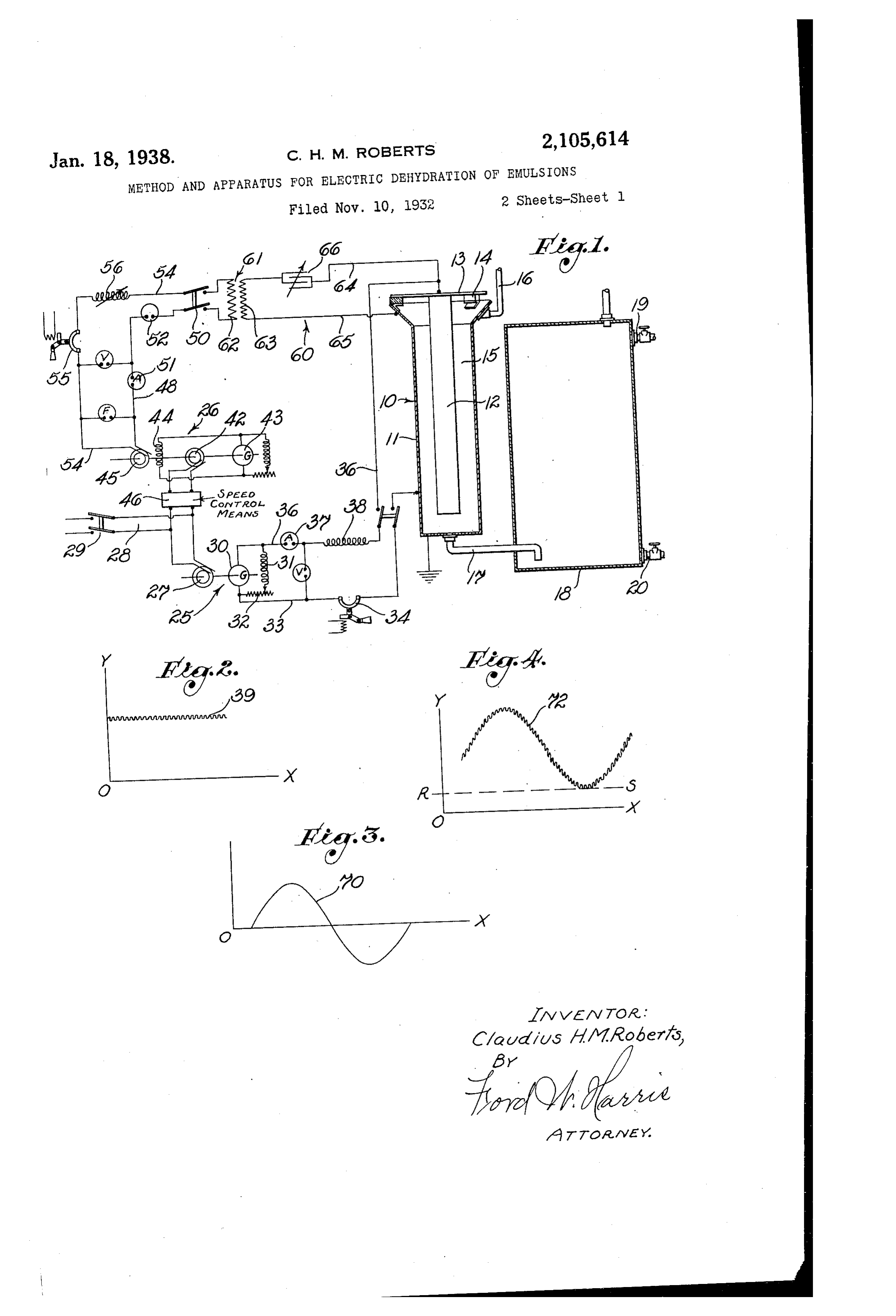
frequency of the alternating potential utilized, it having been found that by properly selecting The source of unidirectional potential 2 is the frequency, it is possible to utilize lower po shown as including a motor-generator set com tentials than would otherwise be necessary. prising a motor 27 energized from a supply line These frequencies are ordinarily higher than the 28 including a switch 29, this motor being con commercial frequency utilized in present dehy nected to a direct current generator 30 includ dration methods, though somewhat lower than ing a shunt field winding 3 in series with a con the radio-frequency range. It is another object trol rheostat 32 for controlling the output volt 0. of the present invention to utilize a frequency age of the generator. One terminal of this gen particularly adapted to the emulsion undergoing erator is connected to a conductor 33 which in treatment and to correspondingly control the cludes a switch 34 and is connected to the tank potentials utilized. 8 which is in turn grounded. The other ter The application of an alternating field tends minal of this generator is connected to a con 5 to elongate the dispersed particles in step with ductor 36 which conducts current to the inner the alternating potential utilized, and it is a electrode 2. An ammeter 37 is preferably further object of the present invention to uti placed in the conductor 36, as is also a choke lize a frequency which causes a maximum elon coil 8, this choke coil preventing the alternating gation or stress at the interface, this being usu component of the field from reaching the gen 20 ally accomplished when the frequency of the al erator 30 and detrimentally affecting the wind ternating potential is adjusted to resonance with ings of the armature or fleld of this generator. the natural period of free vibration of the par ticles. It has been found to be desirable in many in stances to utilize a generator 30 having a rather
Further objects and advantages of the inven pronounced ripple in its output voltage. The 25 tion will be made evident hereinafter. degree of ripple obtainable from a generator is, Referring to the drawings of course, dependent upon several factors, one Fig. 1 is a wiring diagram illustrating one emi of the most important of which is the number of bodiment of the invention supplying both direct commutator segments utilized. If desired a gen current treater. and alternating current potentials to the erator may be used which has a smaller num 30 ber of commutator segments than the conven Fig. 2 is a graphical representation of the di tional types of generators at present in use. In rect current component. Fig. 2 I have illustrated the unidirectional com Fig. 3 is a graphical representation of the al ponent of the potential applied between the elec ternating current component. trodes from the generator 30, the line 9 indi
resultant field.
graphical representation of the cating this potential. The magnitude of this po tential is, of course, represented by the vertical
Fig. 5 issystem.
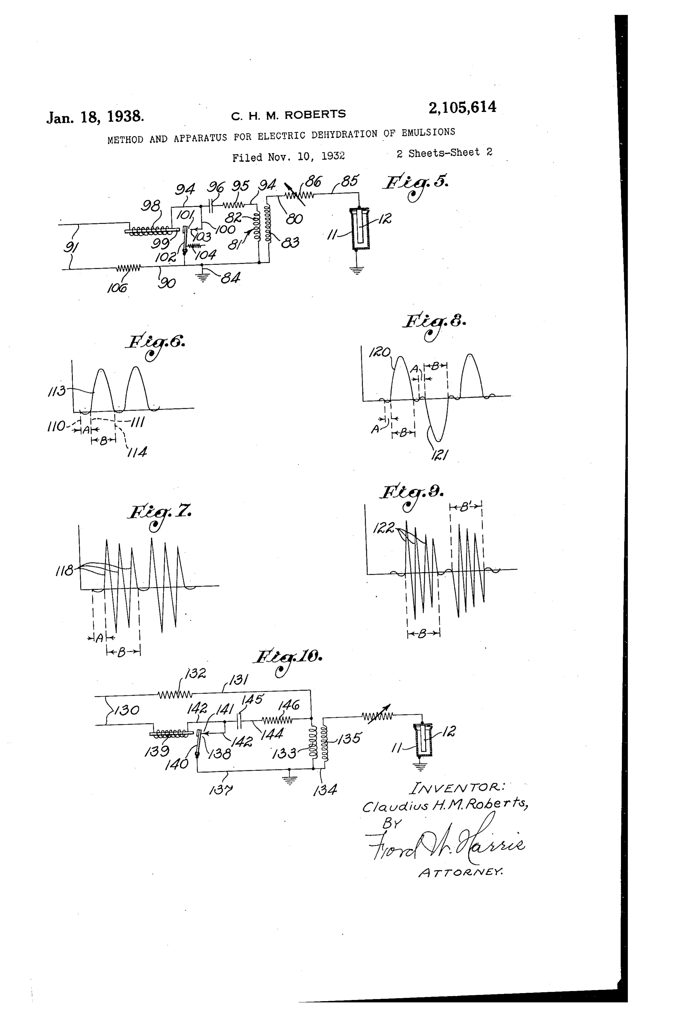
ternative a wiring diagram illustrating an al O-X. distance between the line 39 and the zero axis Figs. 6 and 7 are graphical representations of It should not be understood, however, that I resulting field when the circuit shown in Fig. 5 am limited to the use of a motor-generator set is energized by a direct current potential. for Setting up this unidirectional potential. It FigS. 8 and 9 are graphical representations of is entirely possible to use other devices. Thus, the resulting field when the circuit shown in Fig. if a source of direct current is already avail 5 is energized by alternating current potential. able at the field installation, it is possible to uti Fig. 10 is a wiring diagram of an alternative lize this for Supplying the unidirectional compo form of the invention. nent. In other instances it is possible to rectify Referring particularly to Fig. 1, I have illus the alternating potential supplied by the line 28 45 trated one form of well-known electric treater by the use of well-known rectifiers, such as those indicated in general by the numeral O and in of the vacuum-tube or mercury-vapor type. 50 cluding a shell which forms an outer elec With Such rectifiers it is very easy to obtain the trode. An inner electrode 2 is positioned cen desirable ripple.
trally in the shell and is suspended from a suit The Source of alternating potential 26 is shown 50 able rack 3 supported by insulators 4. Emul as including a motor-generator set including an Sion may be introduced into a treating space 5 alternating current motor 42 directly connected defined between the electrodes through a pipe to a direct current generator 43 which is used 6. After undergoing treatment the emulsion for exciting a field winding 44 of an alternator 45. is discharged through a pipe into a settling By controlling the speed of the motor 42 in any tank 8 where the phases of the emulsion grav Well-known manner by a device such as indi itationally separate, the oil rising to the top of cated by the numeral 46, the frequency output of the tank and being discharged through a pipe the alternator 45 can be varied. Similarly, by 9, and the Water dropping to the bottom of the controlling the voltage output of the generator tank and being discharged through a pipe 20. readily 43 the output varied.voltage of the alternator 45 can be
It will be clear, however, that other types of treaters may be utilized and that the particular One terminal of the alternator 45 is connected type of treater shown need not be used. Thus, to a conductor 48 extending to one blade of a certain other well-known types of treaters may Switch 50. This conductor preferably includes an be utilized in which the electric treatment and ammeter 5 and may include a commutating de 65 the separation take place in the same tank. vice 52 comprising a switch means for periodical In this form of the invention it is desirable ly breaking the circuit. Such a commutating O to utilize a composite field in the treating space means may be mechanically or electrically op f5, and this is accomplished by the use of a erated either in synchronism or out of syn Source of unidirectional potential 25 and a source chronism with the alternating potential derived of alternating potential 26 respectively connected from the alternator 45. The other terminal of to the electrodes and 2 in a manner to be the alternator 45 is connected to a conductor S4 hereinafter described. which extends to another blade of the switch SD and includes an overload circuit-breaker 55 there
Page 5
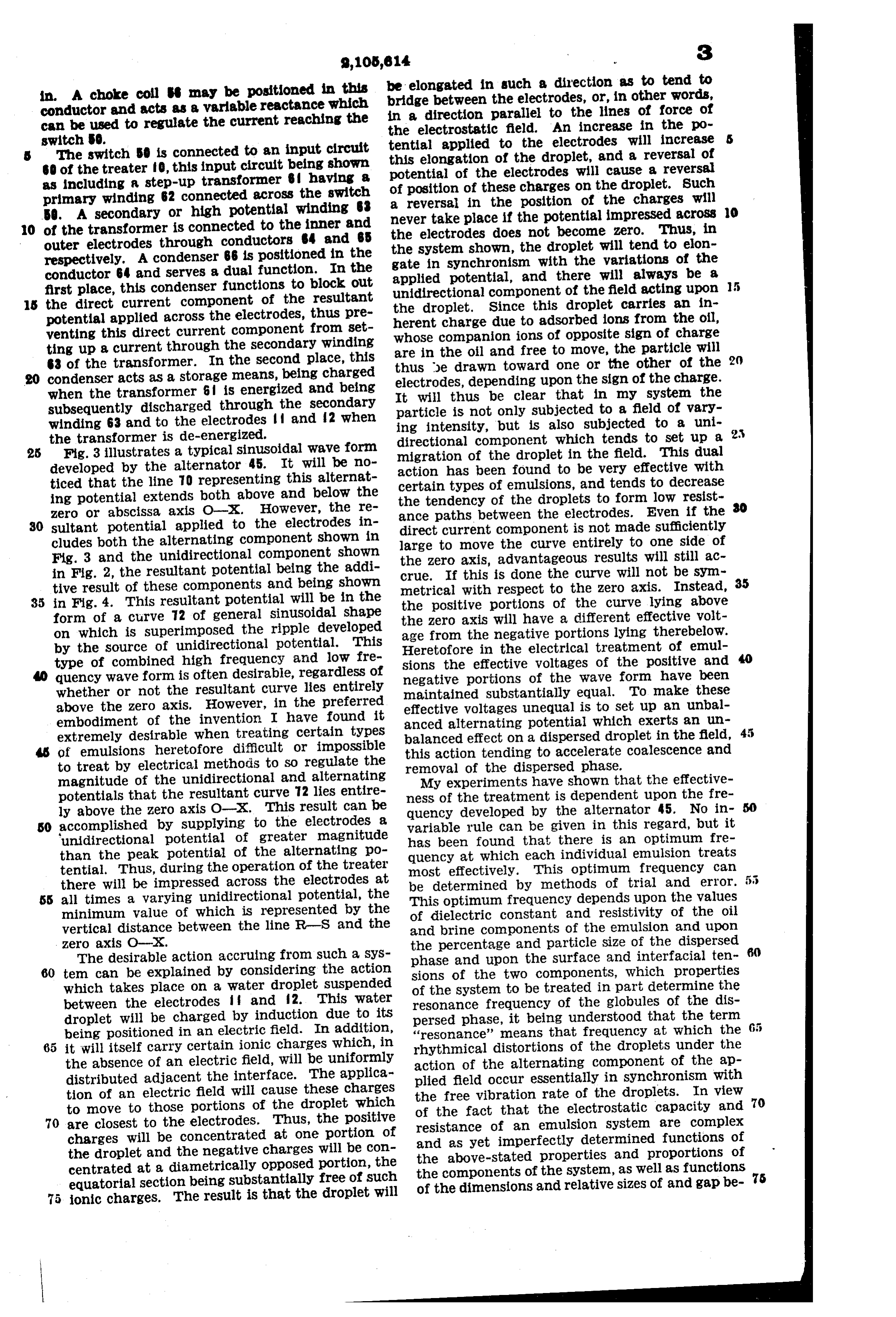
in. A choke coll may be positioned in this be elongated in such a direction as to tend to conductor and acts as a variable reactance which bridge between the electrodes, or, in other words, can be used to regulate the current reaching the in a direction parallel to the lines of force of the electrostatic field. An increase in the po switch 0. tential applied to the electrodes will increase The switch 50 is connected to an input circuit this elongation of the droplet, and a reversal of 60 of the treater f0, this input circuit being shown potential of the electrodes will cause a reversal as including a step-up transformer Bf having a of position of these charges on the droplet. Such primary winding 62 connected across the switch a reversal in the position of the charges will 50. A secondary or high potential winding never take place if the potential impressed across O O of the transformer is connected to the inner and the electrodes does not become zero. Thus, in outer electrodes through conductors 4 and 65 the System shown, the droplet will tend to elon respectively. A condenser B6 is positioned in the gate in synchronism with the variations of the conductor 64 and serves a dual function. In the applied potential, and there will always be a first place, this condenser functions to block Out unidirectional component of the field acting upon s the direct current component of the resultant the droplet. Since this droplet carries an in potential applied across the electrodes, thus pre herent charge due to adsorbed ions from the oil, venting this direct current component from Set whose companion ions of opposite sign of charge ting up a current through the secondary winding are in the oil and free to move, the particle will 63 of the transformer. In the second place, this thus be drawn toward one or the other of the condenser acts as a storage means, being charged electrodes, depending upon the sign of the charge. when the transformer 6 is energized and being It will thus be clear that in my system the subsequently discharged through the secondary particle is not only subjected to a field of vary winding 63 and to the electrodes and 2 when ing intensity, but is also subjected to a uni the transformer is de-energized. directional component which tends to set up a 2. 25 Fig. 3 illustrates a typical sinusoidal wave form migration of the droplet in the field. This dual developed by the alternator 45. It will be no action has been found to be very effective with ticed that the line TO representing this alternat Certain types of emulsions, and tends to decrease ing potential extends both above and below the the tendency of the droplets to form low resist zero or abscissa axis O-X. However, the re ance paths between the electrodes. Even if the 30 Sultant potential applied to the electrodes in direct current component is not made sufficiently cludes both the alternating component shown in large to move the curve entirely to one side of Fig. 3 and the unidirectional component shown the Zero axis, advantageous results will still ac in Fig. 2, the resultant potential being the addi Crue. If this is done the curve will not be sym tive result of these components and being shown metrical with respect to the zero axis. Instead, 35 35 in Fig. 4. This resultant potential will be in the the positive portions of the curve lying above form of a curve 72 of general sinusoidal shape the Zero axis Will have a different effective volt on which is superimposed the ripple developed age from the negative portions lying therebelow. by the source of unidirectional potential. This Heretofore in the electrical treatment of emul type of combined high frequency and low fre Sions the effective voltages of the positive and quency wave form is often desirable, regardless of negative portions of the wave form have been whether or not the resultant curve lies entirely maintained Substantially equal. To make these above the zero axis. However, in the preferred effective voltages unequal is to set up an unbal embodiment of the invention I have found it anced alternating potential which exerts an un extremely desirable when treating certain types balanced effect on a dispersed droplet in the field, of emulsions heretofore difficult or impossible this action tending to accelerate coalescence and to treat by electrical methodis to SO regulate the removal of the dispersed phase. magnitude of the unidirectional and alternating My experiments have shown that the effective potentials that the resultant curve 72 lies entire ness of the treatment is dependent upon the fre ly above the Zero axis O-X. This result can be quency developed by the alternator 45. No in SO accomplished by supplying to the electrodes a Variable rule can be given in this regard, but it unidirectional potential of greater magnitude has been found that there is an optimum fre than the peak potential of the alternating po quency at which each individual emulsion treats tential. Thus, during the operation of the treater most effectively. This optimum frequency can there will be impressed across the electrodes at be determined by methods of trial and error. 55 SS all times a varying unidirectional potential, the This optimum frequency depends upon the values minimum value of which is represented by the of dielectric constant and resistivity of the oil vertical distance between the line R-S and the and brine components of the emulsion and upon Zero axis O-X. the percentage and particle size of the dispersed The desirable action accruing from such a sys phase and upon the surface and interfacial ten s tem can be explained by considering the action sions of the two components, which properties which takes place on a Water droplet suspended of the system to be treated in part determine the between the electrodes and f2. This water resonance frequency of the globules of the dis droplet will be charged by induction due to its persed phase, it being understood that the term 65 being positioned in an electric field. In addition, “resonance' means that frequency at which the 65 it will itself carry certain ionic charges which, in rhythmical distortions of the droplets under the the absence of an electric field, will be uniformly action of the alternating component of the ap distributed adjacent the interface. The applica plied field occur essentially in synchronism with tion of an electric field will cause these charges the free vibration rate of the droplets. In view to move to those portions of the droplet which of the fact that the electroStatic capacity and 70 70 are closest to the electrodes. Thus, the positive resistance of an emulsion System are complex charges will be concentrated at One portion of and as yet imperfectly determined functions of the droplet and the negative charges will be con the above-stated properties and proportions of centrated at a diametrically opposed portion, the equatorial section being substantially free of such the
components of the system, as well as functions 5 the dimensions and relative sizes of and gap be ionic charges. The result is that the droplet will
Page 6
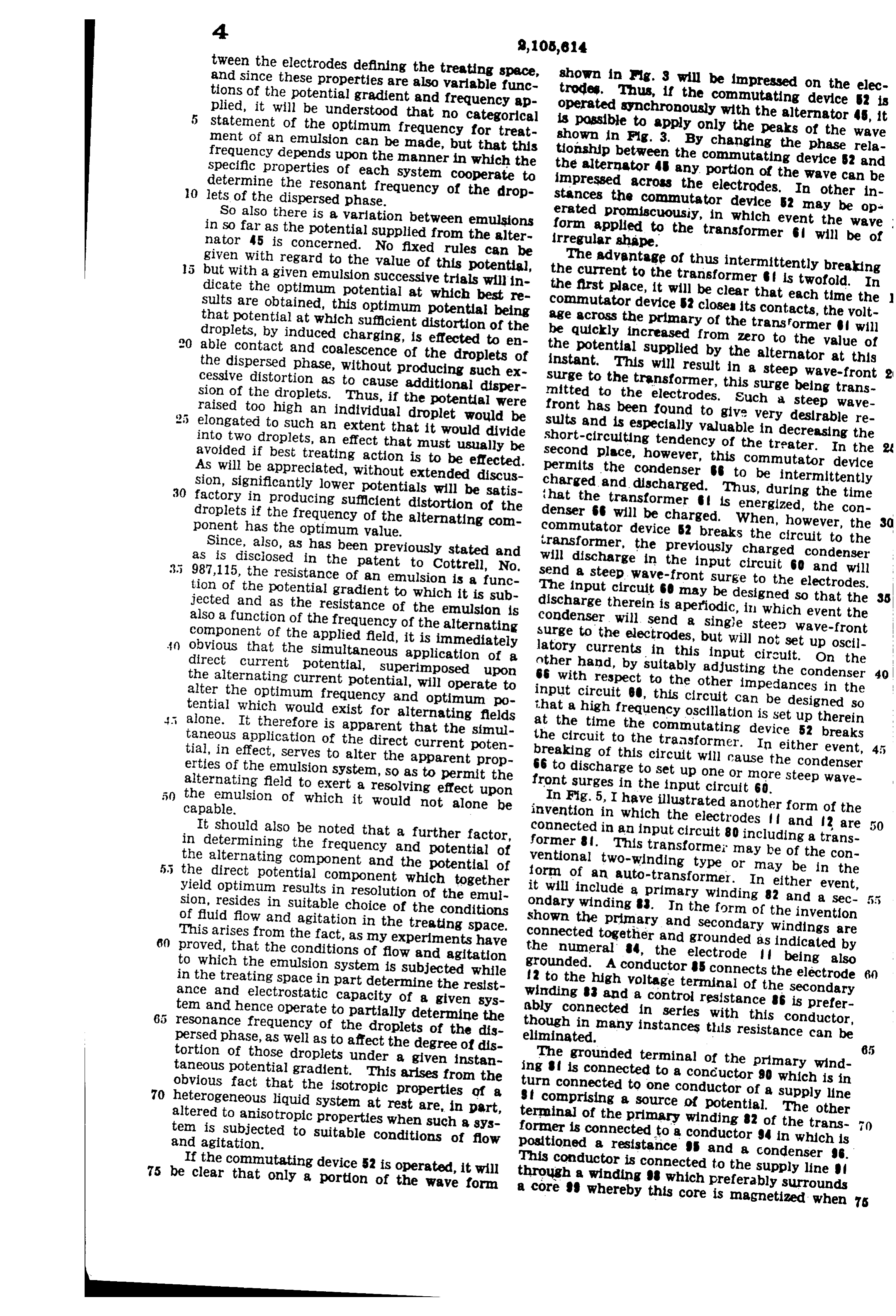
tween the electrodes defining the treating space, and since these properties are also variable funct shown in rig. 3 will be impressed on the elec tions of the potential gradient and frequency ap trodes. Thus, if the commutating device S2 is plied, it will be understood that no categorical operated synchronously with the alternator 45, it statement of the optimum frequency for treat is possible to apply only the peaks of the wave ment of an emulsion can be made, but that this shown in Fig. 3. By changing the phase rela frequency depends upon the manner in which the tionship between the commutating device S2 and specific properties of each System cooperate to the alternator 4 any portion of the wave can be O determine the resonant frequency of the drop impressed across the electrodes. In other in lets of the dispersed phase. stances the commutator device 52 may be op So also there is a variation between emulsions erated promiscuously, in which event the wave form applied in so far as the potential supplied from the alter irregular shape.to the transformer will be of nator 45 is concerned. No fixed rules can be given with regard to the value of this potential, The advantage of thus intermittently breaking but with a given emulsion successive trials will in the current to the transformer is twofold. In dicate the optimum potential at which best re the first place, it will be clear that each time the sults are obtained, this optimum potential being commutator device S2 closes its contacts, the volt that potential at which sufficient distortion of the age across the primary of the transformer will droplets, by induced charging, is effected to en be quickly increased from Zero to the value of able contact and coalescence of the droplets of the potential supplied by the alternator at this the dispersed phase, without producing such ex instant. This will result in a steep wave-front cessive distortion as to cause additional disper surge to the transformer, this surge being trans sion of the droplets. Thus, if the potential were nnitted to the electrodes. Such a steep wave 2 5 raised too high an individual droplet would be front has been found to give very desirable re elongated to such an extent that it would divide sults and is especially valuable in decreasing the into two droplets, an effect that must usually be short-circuiting tendency of the treater. In the avoided if best treating action is to be effected. second place, however, this commutator device As will be appreciated, without extended discus permits the condenser to be intermittently 30 sion, significantly lower potentials will be satis charged and discharged. Thus, during the time factory in producing sufficient distortion of the that the transformer is energized, the con droplets if the frequency of the alternating com denser it will be charged. When, however, the 30 ponent has the optimum value. commutator device 2 breaks the circuit to the Since, also, as has been previously stated and transformer, the previously charged condenser 3.5 as is disciosed in the patent to Cottrell, No. will discharge in the input circuit 60 and will 987,115, the resistance of an emulsion is a func send a steep wave-front Surge to the electrodes. tion of the potential gradient to which it is sub The input circuit GO may be designed so that the jected and as the resistance of the emulsion is discharge therein is aperiodic, in which event the also a function of the frequency of the alternating condenser will send a single steep wave-front component of the applied field, it is immediately surge to the electrodes, but will not set up oscil obvious that the simultaneous application of a latory currents in this input circuit. On the direct current potential, superimposed upon anther hand, by suitably adjusting the condenser the alternating current potential, will operate to 66 with respect to the other impedances in the alter the optimum frequency and optimum po input circuit B, this circuit can be designed so tential which would exist for alternating fields that a high frequency oscillation is set up therein alone. It therefore is apparent that the simul at the time the commutating device 52 breaks taneous application of the direct current poten the circuit to the transformer. In either event, tial, in effect, serves to alter the apparent prop breaking of this circuit will cause the condenser erties of the emulsion system, so as to permit the 66 to discharge to set up one or more steep wave alternating field to exert a resolving effect upon front surges in the input circuit 60. the emulsion of which it would not alone be capable. In Fig. 5, I have illustrated another form of the invention in which the electrodes and 2 are
It should also be noted that a further factor, connected in an input circuit 80 including a trans in determining the frequency and potential of former 8. This transformer may be of the con the alternating component and the potential of ventional two-winding type or may be in the 5 the direct potential component which together form of an auto-transformer. In either event, yield optimum results in resolution of the emul it will include a primary winding 82 and a sec sion, resides in suitable choice of the conditions ondary winding . In the form of the invention of fluid flow and agitation in the treating Space. shown the primary and secondary windings are 60 This arises from the fact, as my experiments have connected together and grounded as indicated by proved, that the conditions of flow and agitation the numeral 4, the electrode being also to which the emulsion system is subjected while grounded. A conductor 5 connects the electrode 6) in the treating space in part determine the resist f2 to the high voltage terminal of the secondary ance and electrostatic capacity of a given sys winding 3 and a control resistance 6 is prefer tem and hence operate to partially determine the ably connected in series with this conductor, resonance frequency of the droplets of the dis though in many instances this resistance can be persed phase, as well as to affect the degree of dis eliminated.
tortion of those droplets under a given instan The grounded terminal of the primary wind taneous potential gradient. This arises from the ing f is connected to a conductor 90 which is in 70 obvious fact that the isotropic properties of a turn connected to one conductor of a supply line heterogeneous liquid system at rest are, in part, 9 comprising a source of potential. The other altered to anisotropic properties when such a sys terminal of the primary winding 82 of the trans tem is subjected to suitable conditions of flow former is connected to a conductor 94 in which is and agitation. positioned a resistance and a condenser 96. 75 be Ifclearthe commutating device 52 is operated, it will This conductor is connected to the supply line that only a portion of the wave form through a winding which preferably surrounds a core 99 whereby this core is magnetized when 76
Page 7
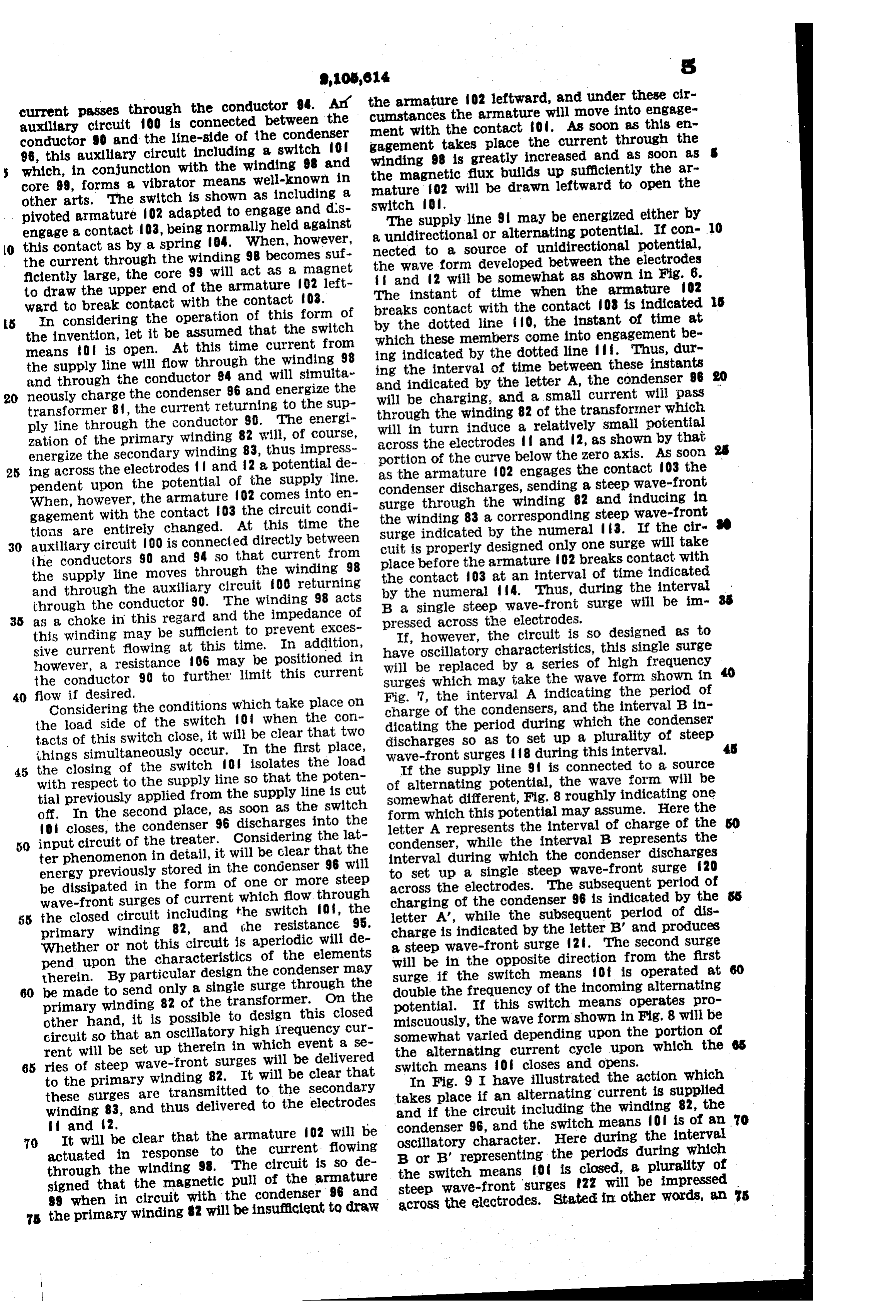
current passes through the conductor 94. Ar? the armature f O2 leftward, and under these cir cumstances the armature will move into engage auxiliary circuit OO is connected between the ment with the contact fol. As soon as this en conductor 90 and the line-side of the condenser gagement takes place the current through the 98, this auxiliary circuit including a switch of winding 98 is greatly increased and as soon as which, in conjunction with the winding 98 and the magnetic flux builds up sufficiently the ar core 99, forms a vibrator means well-known in mature 02 will be drawn leftward to open the other arts. The switch is shown as including a SWitch 0.
pivoted armature O2 adapted to engage and dis The supply line 9 may be energized either by engage a contact 03, being normally held against a unidirectional or alternating potential. If con 10 this contact as by a spring 04. When, however, nected to a source of unidirectional potential, the current through the winding 98 becomes suf the Wave form developed between the electrodes fliciently large, the core 99 will act as a magnet and 2 will be somewhat as shown in Fig. 6. to draw the upper end of the armature O2 left The instant of time when the armature fo2 s ward to break contact with the contact 03.
5 In considering the operation of this form of breaks contact with the contact 03 is indicated by the dotted line i? 0, the instant of time at the invention, let it be assumed that the Switch which these members come into engagement be means of is open. At this time current from ing indicated by the dotted line ff. Thus, dur the supply line will flow through the winding 98 ing the interval of time between these instants and through the conductor 94 and will simulta and indicated by the letter A, the condenser 96 20 neously charge the condenser 96 and energize the will be charging, and a small current will pass transformer 8, the current returning to the Sup through the winding 82 of the transformer which ply line through the conductor 90. The energin Will in turn induce a relatively small potential zation of the primary winding 82 will, of course, across the electrodes and 2, as shown by that energize the secondary winding 83, thus impress portion of the curve below the zero axis. As soon 25 ing across the electrodes and 2 a potential de as the armature f O2 engages the contact 03 the pendent upon the potential of the Supply line. Condenser discharges, sending a steep wave-front When, however, the armature 02 comes into en Surge through the winding 82 and inducing in gagement with the contact 03 the circuit condi the winding 83 a corresponding steep wave-front tions are entirely changed. At this time the Surge indicated by the numeral 3. If the cir 30 auxiliary circuit OO is connected directly between cuit is properly designed only one surge will take the conductors 90 and 94 so that current from place before the armature f O2 breaks contact with the supply line moves through the winding 98 the contact 03 at an interval of time indicated and through the auxiliary circuit OO returning by the numeral 4. Thus, during the interval through the conductor 90. The winding 98 acts B a single steep wave-front Surge will be im 35 as a choke in this regard and the impedance of preSSed acroSS the electrodes. this winding may be sufficient to prevent exces If, however, the circuit is so designed as to sive current flowing at this time. In addition, have oscillatory characteristics, this single surge however, a resistance 106 may be positioned in will be replaced by a series of high frequency the conductor 90 to further limit this current Surges which may take the wave form shown in 40 flow if desired. Fig. 7, the interval A indicating the period of Considering the conditions which take place on charge of the condensers, and the interval B in the load side of the switch of when the con dicating the period during which the condenser tacts of this switch close, it will be clear that two discharges So as to set up a plurality of steep things simultaneously occur. In the first place, wave-front surges 18 during this interval. 45 the closing of the switch 0 isolates the load If the supply line 9 is connected to a source with respect to the supply line so that the poten of alternating potential, the wave form will be tial previously applied from the supply line is cut somewhat different, Fig. 8 roughly indicating one off. In the second place, as soon as the switch form which this potential may assume. Here the of closes, the condenser 96 discharges into the letter A represents the interval of charge of the 50 input circuit of the treater. Considering the lat condenser, while the interval B represents the ter phenomenon in detail, it will be clear that the interval during which the condenser discharges energy previously stored in the condenser 96 will to set up a single steep wave-front surge 20 be dissipated in the form of one or more steep across the electrodes. The subsequent period of wave-front surges of current which flow through charging of the condenser 96 is indicated by the 55 the closed circuit including the switch 0 , the letter A', while the subsequent period of dis primary winding 82, and the resistance 95. charge is indicated by the letter B.’ and produces Whether or not this circuit is aperiodic will de a steep wave-front surge 2. The second surge pend upon the characteristics of the elements will be in the opposite direction from the first therein. By particular design the condenser may Surge. if the Switch means of is operated at 60 be made to send only a single surge through the double the frequency of the incoming alternating primary winding 82 of the transformer. On the potential. If this Switch means operates pro other hand, it is possible to design this closed miscuously, the wave form shown in Fig. 8 will be circuit so that an oscillatory high requency cur Somewhat varied depending upon the portion of rent will be set up therein in which event a se the alternating current cycle upon which the 65 ries of steep wave-front Surges will be delivered Switch means of closes and opens. to the primary winding 82. It will be clear that In Fig. 9 I have illustrated the action which these surges are transmitted to the secondary takes place if an alternating current is supplied winding 83, and thus delivered to the electrodes and if the circuit including the winding 82, the ft and 2. condenser 96, and the switch means Of is of an 70 It will be clear that the armature 02 will be Oscillatory character. Here during the interval 70 actuated in response to the current flowing B or B' representing the periods during which through the winding 98. The circuit is so de the switch means of is closed, a plurality of signed that the magnetic pull of the armature steep wave-front surges 22 will be impressed 99 when in circuit with the condenser 96 and across the electrodes. Stated in other words, an s 75 the primary winding 2 will be insufficient to draw
Page 8
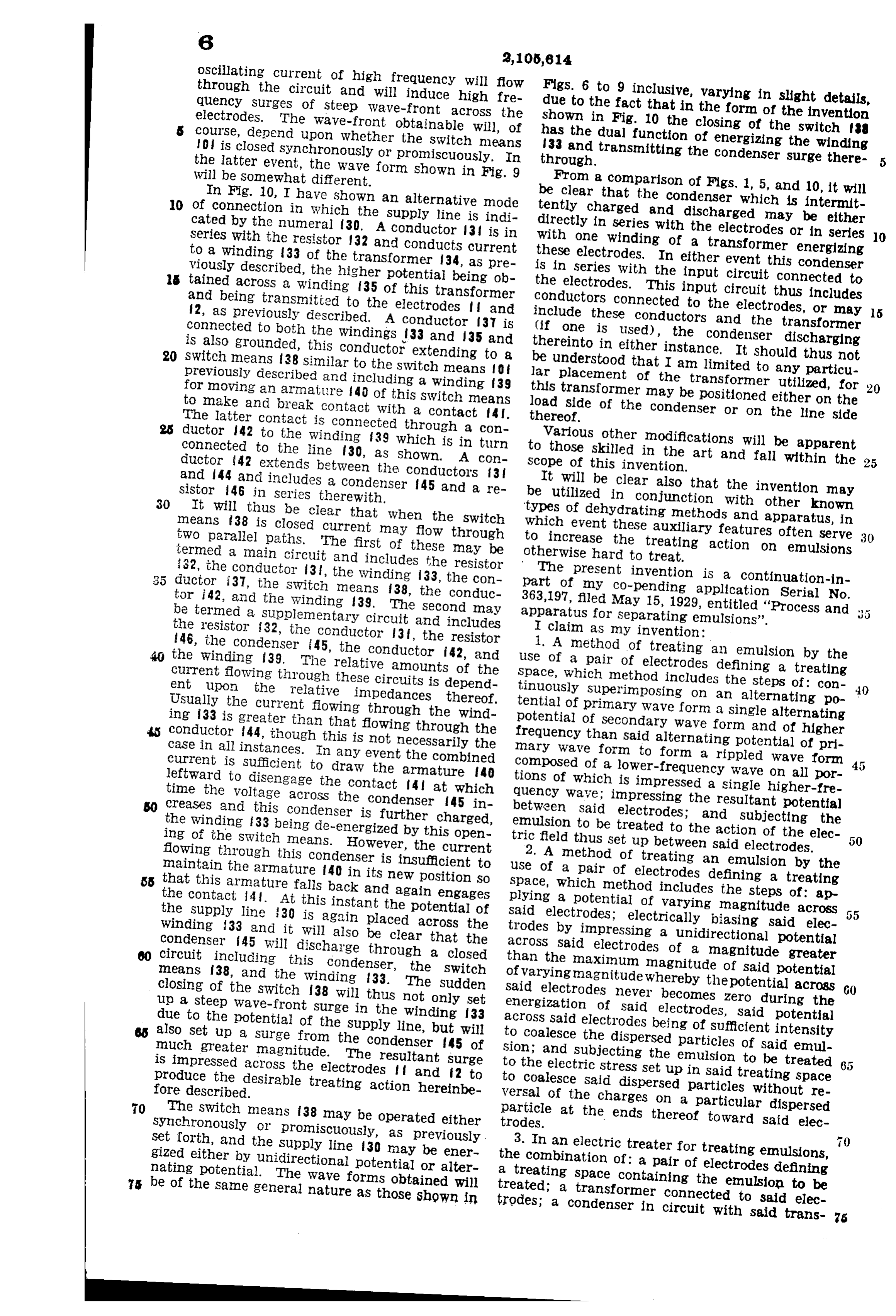
oscillating current of high frequency Will flow through the circuit and will induce high fre FigS. 6 to 9 inclusive, varying in slight details, quency surges of steep Wave-front across the due to the fact that in the form of the invention electrodes. The wave-front obtainable will, of shown in Fig. 10 the closing of the switch 88 course, depend upon whether the Switch means has the dual function of energizing the winding O is closed synchronously or promiscuously. In 33 and transnitting the condenser surge there the latter event, the wave form shown in Fig. 9 through.
Will be somewhat different. From a comparison of Figs. 1, 5, and 10, it will 0 of In Fig. 10, I have shown an alternative mode be clear that the condenser which is intermit connection in which the Supply line is indi tently charged and discharged may be either cated by the numeral 30. A conductor 3 is in directly in series with the electrodes or in series O Series with the resistor 32 and conducts current with one winding of a transformer energizing to a winding 33 of the transformer 34, as pre these electrodes. In either event this condenser viously described, the higher potential being ob 5 tained across a winding 35 of this transformer is in Series with the input circuit connected to the electrodes. This input circuit thus includes and being transmitted to the electrodes and conductors connected to the electrodes, or may 5 2, as previously described. A conductor 37 is include these conductors and the transformer connected to both the windings 33 and 135 and (if one is used), the condenser discharging S20 is also grounded, this conductor extending to a thereinto in either instance. It should thus not Switch means 38 similar to the switch means of be understood that I am limited to any particu previously described and including a winding 39 lar placement of the transformer utilized, for for moving an armature 40 of this Switch means this transformer may be positioned either on the to make and break contact with a contact 4. load Side of the condenser or on the line side The latter contact is connected through a con thereof.
ductor 42 to the winding 39 which is in turn Various other modifications will be apparent connected to the line 30, as shown. A con to those skilled in the art and fall within the ductor 42 extends between the conductors 3 scope of this invention.
and 44 and includes a condenser 45 and a re It will be clear also that the invention may sistor 46 in Series therewith. be utilized in conjunction with other known
It will thus be clear that when the switch types of dehydrating methods and apparatus, in means 38 is closed current may flow through which event these auxiliary features often serve two parallel paths. The first of these may be to increase the treating action. On emulsions 30 termed a main circuit and includes the resistor otherwise hard to treat.
S5 32, the conductor 3, the winding 33, the con part The present invention is a continuation-in of my co-pending application Serial No.
ductor 3, the Switch means 38, the conduc tor 42, and the winding 39. The second may 363,197, filed May 15, 1929, entitled "Process and be termed a supplementary circuit and includes apparatus for separating emulsions'. 5 the resistor 32, the conductor 3, the resistor I claim as my invention: 30 the 46, the condenser 45, the conductor i42, and 1. A method of treating an emulsion by the winding 39. The relative amounts of the use of a pair of electrodes defining a treating current flowing through these circuits is depend space, which method includes the steps of: con ent upon the relative impedances thereof. tinuously superimposing on an alternating po 40 Usually the current flowing through the wind tential of primary wave form a single alternating ing 33 is greater than that flowing through the potential of Secondary wave form and of higher conductor 44, though this is not necessarily the frequency than said alternating potential of pri case in all instances. In any event the combined mary wave form to form a rippled wave form current is sufficient to draw the armature 40 composed of a lower-frequency wave on all por leftward to disengage the contact 4 at which tions of which is impressed a single higher-fre time the voltage across the condenser 45 in quency wave; impressing the resultant potential creases and this condenser is further charged, between said electrodes; and subjecting the the winding 33 being de-energized by this open emulsion to be treated to the action of the elec ing of the Switch means. However, the current tric field thus set up between said electrodes. flowing through this condenser is insufficient to 2. A method of treating an emulsion by the maintain the armature f 40 in its new position so use of a pair of electrodes defining a treating SS that this armature falls back and again engages space, which method includes the steps of: ap the contact 4. At this instant the potential of plying a potential of varying magnitude across the Supply line 30 is again placed across the said electrodes; electrically biasing said elec winding 33 and it will also be clear that the trodes by impressing a unidirectional potential condenser 45 will discharge through a closed across said electrodes of a magnitude greater circuit including this condenser, the switch than the maximum magnitude of said potential means 38, and the winding 33. The Sudden of varying magnitude whereby the potential across closing of the switch 38 will thus not only set Said electrodes never becomes zero during the 60 up a steep wave-front surge in the winding 33 energization of said electrodes, Said potential due to the potential of the supply line, but will across said electrodes being of sufficient intensity also set up a Surge from the condenser 45 of to coalesce the dispersed particles of said emul much greater magnitude. The resultant surge sion; and subjecting the emulsion to be treated is impreSSed across the electrodes and 2 to to the electric StreSS Set up in Said treating space produce the desirable treating action hereinbe to coalesce Said dispersed particles without re fore described. Versal of the charges on a particular dispersed The Switch means 38 may be operated either particle
Synchronously or promiscuously, as previously. trodes. at the ends thereof toward said elec Set forth, and the Supply line 30 may be ener 3. In an electric treater for treating emulsions, gized either by unidirectional potential or alter the combination of: a pair of electrodes defining nating potential. The wave forms obtained will a treating space containing the emulsion to be be of the Same general nature as those shown in treated; a transformer connected to said elec trodes; a condenser in circuit with said trans 5
Page 9
ternating potential and said source of unidirec former and storing electric energy during the tional potential to said electrodes whereby the time said transformer is energized; a source of resultant potential difference between said elec potential; and switch means for periodically en trodes never drops to zero during the application ergizing said transformer from said source of of said potentials and means for periodically iso potential and subsequently deemergizing said lating one of said sources from said electrodes transformer to permit said condenser to dis for only a short period of time during the time charge to set up a steep wave-front surge to said said other source is connected thereto. electrodes. 9. A method of electrically treating an emul 4. In an electric treater for treating emulsions, sion between electrodes, which method includes O the combination of: a pair of electrodes between the steps of: applying an alternating potential O which is positioned the emulsion to be treated; across said electrodes; electrically biasing said a potential supply means; a condenser connected electrodes by applying thereto a unidirectional in circuit with said potential Supply means; an potential; and periodically disconnecting and re 5 input circuit connected to said potential supply applying one of said potentials to said electrodes means through said condenser and connected to while the other potential remains applied thereto. said electrodes to set up an electric field there 10. A method of electrically treating an emul between; an auxiliary circuit connecting said con sion between electrodes by the use of a source of denser in closed circuit with said input circuit alternating potential and a condenser, which whereby said condenser can discharge into said method includes the steps of: energizing said 20 input circuit through said auxiliary circuit; and electrodes and charging Said condenser by con a switch means in said auxiliary circuit for peri necting said source of alternating potential there odically closing same to discharge said condenser to; then isolating said Source of alternating po into said input circuit. tential from said electrodes; and discharging said 5. In an electric treater for treating emulsions, condenser to said electrodes during said isolation 25 25 the combination of: a pair of electrodes between of said source of alternating potential therefrom which is positioned the emulsion to be treated; a whereby said emulsion is first Subjected to a field potential supply means providing a pair of con set up between said electrodes by said source of ductors; a transformer connected to said elec alternating potential and is then subjected to a 30 trodes and supplied with current fron said po steep wave front surge developed by the discharge 30 tential supply means; a condenser connected to of said condenser.
said transformer, the line side of said condenser 11. A method of electrically treating an emul being connected to one of said conductors; and sion between electrodes by the use of a source of switch means for periodically connecting the line alternating potential and a condenser, which 35 side of said condenser to said transformer to dis nethod includes the steps of: energizing said 35 charge said condenser into said transformer to electrodes and charging Said condenser by con send a steep wave-front surge to said electrodes. necting said source of alternating potential there 6. In an electric treater for treating emulsions, to; then simultaneously isolating said source of the combination of: a pair of electrodes between alternating potential from Said electrodes and 40 which is the emulsion to be treated; a transformer discharging said condenser thereto to form a providing a primary and a secondary windirig, surge to said electrodes at the extreme end of the said secondary winding being electrically con period of application of said alternating poten nected to said electrodes to build up a potential tial whereby said emulsion is first Subjected to a difference therebetween; a condenser; means for field set up between said electrodes by said source charging said condenser; and switch means op of alternating potential and is then immediately 45 erating periodically and connecting said con subjected to a steep wave front surge developed denser in closed circuit with said primary wind by the discharge of said condenser; and subse ing whereby the charge on said condenser is de quently re-energizing said electrodes and said livered to said primary winding to provide a steep condenser.
wave-front Surge to said electrodes. 12. A method of treating an emulsion between 50 7. In an electric treater for treating emulsions, electrodes, which method includes the steps of: the combination of: a pair of electrodes between applying to said electrodes an alternating poten which is positioned the emulsion to be treated; tial; simultaneously electrically biasing said elec a potential supply means providing a pair of con trodes by applying thereto a rippled direct cur ductors; a magnetic means including a winding rent potential, the frequency of the ripple being 55 in circuit with one of said conductors; a switch much greater than the frequency of said alter means operated in response to the current flow nating potential; and subjecting the emulsion to ing through said winding and connected to said the resultant field produced between said elec winding and to the other of said conductor trodes to coalesce the dispersed phase of Said means whereby current flows through said wind ing and said switch means in series when said emulsion.13. A method of electrically treating an emul Switch means is closed; an input circuit con sion including a continuous phase with dispersed nected to said electrodes; condenser means con liquid particles therein, which method includes nected to said input circuit to discharge therein; the steps of: impressing across an electrode 65 and means connecting said input circuit and said bounded treating space an alternating potential condenser across said switch means whereby clos of a frequency substantially corresponding to the ing of said switch means discharges said con resonant free vibration rate of said particles; denser therethrough and into said input circuit. electrically biasing said electrodes with a unidi 8. In an electric treater for treating an emul rectional potential to produce a resultant field; sion, the combination of: a pair of electrodes be and causing coalescence of said dispersed liquid 70 tween which is positioned the emulsion to be particles by subjecting said emulsion to the action treated; a source of alternating potential; a of said resultant field.
source of unidirectional potential delivering a 14. In an electric treating system for treating unidirectional potential of a magnitude greater an emulsion, the combination of: a pair of elec than the peak potential of said alternating po trodes between which is positioned the emulsion 75 5 tential; means for connecting said source of al

Page 10
to be treated; a source of unidirectional poten particles forming the dispersed phase of said tial; means connecting said source of unidirec emulsion.
tional potential across said electrodes; a Source of alternating potential; means for connecting 17. A method of treating an emulsion contain said source of alternating potential across Said ing an aqueous phase dispersed in a continuous electrodes; a condenser means in circuit with said phase, which method includes the steps of: nov last-named means and preventing any of said ing a stream of said emulsion into a treating unidirectional potential from reaching said source Space; coalescing the dispersed aqueous particles of alternating potential; and means for peri and causing some degree of migration thereof by O odically discharging said condenser means to establishing in said treating space an unbalanced Said électrodes. alternating field having peak potentials on One lo 15. A method of electrically treating an ennul side of the Zero axis which are greater than the sion between electrodes by the use of a potential peak potentials on the other side of said axis, ls source and a condenser, which method includes the time interval of application of the potentials the steps of: charging said condenser before con On Said one side being greater than on said other necting said electrodes to Said potential Source; side; moving the treated emulsion constituents 5 and thereafter simultaneously connecting said from said field before complete separation of the condenser and said potential source to said elec phase liquids has taken place; and thereafter 20 trodes to produce a surge to said electrodes from Said further separating the phase liquids present in the discharge of said condenser at the instant treated emulsion constituents. said electrodes are energized by said potential 18. A method as defined in clain 17 in which 20 Source, said surge dying out during the period of Said electric field is established by impressing connection trodeS. of said potential source to said elec across Spaced portions of said treating space a single alternating potential and a unidirectional 16. In an electric treating System for emul biasing potential of a magnitude less than the sions, the combination of: a potential supply peak potential of said single alternating poten- 25 means; a pair of electrodes between which is tial.
positioned the emulsion to be treated; electrode 19. In combination in a system for treating 30 energizing conductor means acting to energize emulsions: a pair of electrodes bounding a treat said electrode means, circuit means electrically ing space containing emulsion to be treated; a connecting said potential supply means to said Source of potential; a condenser; circuit means 30 electrode-energizing conductor means; Switch connecting said electrodes, said source of poten means connected across Said circuit means; tial, and said condenser to energize said elec means for periodically closing said Switch means trodes and establish an electric Stress in Said to periodically shunt said circuit means to de treating space; switch means in said circuit crease the normal potential applied to said elec ing means for charging said condenser and discharg- 3s trodes by said potential supply means; and a Operating same to said electrodes; a movable member condenser in series circuit with said electrodes said Switch means; and magnetic 40 and said Switch means when said switch means is means providing a winding in Said circuit means closed whereby closing of said switch means also to move said movable member in response to the current flowing in a portion of said circuit means. 40 closes this series circuit to allow said condenser 20. A combination as defined in claim 3 in to discharge to said electrodes, opening of said which said transformer includes a primary wind
Switch means thus re-applying the normally ap ing and a secondary winding and in which said plied potential of said potential supply means to condenser, said secondary winding and said elec Said electrodes, said normally applied potential trodes are connected in series relationship, and in 5 of Said potential supply means and said surge be which said switch means is in circuit with said ing of Sufficient intensity to coalesce the dispersed primary winding of said transformer.
CLAUDIUS H. M. ROBERTS.
CERTIFICATE OF CORRECTION.
CLAUDIUS H. M. ROBERTS.
It is hereby certified that error appears in the printed specification of the above numbered patent requiring correction as follows: Page 8, first column, line 59, claim l6, for the word "electrodes" read electrode-ener gizing conductor means; and that the said Letters Patent should be read
With this correction therein that the same may conform to the record of the case in the Patent Office.
Signed and sealed this 3d day of May, A. D. l938.
(Seal) Henry Van Arsdale, Acting Comissioner of Patents.
Provenance
- Collection
- Cited prior art
- Original PDF
- patentimages.storage.googleapis.com →
- Filed
- 1932-11-10
- Pages
- 10
- Method
- pdftotext (the PDF's own text layer) + pdftoppm 300dpi page scans
- Source
- Google Patents bibliographic record
- Granted
- 1938-01-18
- Inventors
- Claudius H M Roberts; PETROLEUM RECTIFYING CO
- Transcribed from
- patentimages.storage.googleapis.com →