patent · US4270512
Heat storing fireplace
2 June 1981
Page 1 — bibliographic record
United States Patent (19) (11) 4,270,512 Van Der M 45) Jun. 2, 1981 54) HEAT STORING FIREPLACE by a heat storage medium which is either an enclosure 76 Inventor: Robert E. Van Der Maas, 2020 NE. containing a material having a high specific heat such as 127th St., Seattle, Wash.98125 sand or gravel or a large number of heat conducting bags containing a high specific heat material. Exhaust 21 Appi. No.: 883,651 gases are conveyed from the fire-box to an exhaust (22 Filed: Mar. 6, 1978 outlet by several conduits extending through the heat 51) Int. Cl. ................................................ F24B 7/00 storage medium in a circuitous path in order to transfer 52) U.S. C. .................................... 126/121; 126/400; heat from the exhaust gases to the heat storage medium. 126/132; 126/143; 165/46; 165/104.17 Heat is further distributed through the storage material 58 Field of Search ............... 126/400, 120, 121, 143, by a heat conducting lattice fastened to the conduits and 126/122, 123, 124, 131, 132; 165/DIG. 4, 104 extending through the storage medium in a circuitous S, 46, 146; 637/55 path. Combustion air enters the bottom of the fire box through a combustion air inlet jacket surrounding the 56) References Cited exhaust outlet in order to simultaneously pre-warm the
2,243,503 5/1941 Frenette ................................. 237/55 outlet from its support structure. A draft is created 3,073,575 l/1963 Schulenberg ..... ... 165/146 through the fire-box by an exhaust fan mounted in the 3,773,031 11/1973 Laing et al. ... ... 165/104 S exhaust outlet. Although the heat storage medium is 3,960,205 6/1976. Laing ......... ... 165/104 S primarily heated by burning fuel in the fire-box, it may 3,960,207 6/976 Boer ..................................... 126/400 also be heated by either an electric grill or solar heat 4,037,583 7/1977 Bakun et al. ... 126/400X exchanger embedded in the heat storage medium. The 4,049,194 9/1977 Tice et al. ........................ 26/122 X upper portion of the storage medium is covered by a 4,089,142 5/1978 Kachadorian ................... 26/400X 4,142,576 3/1979 Perry et al. ....................... 165/104 S ventilating plenum which allows heat to escape from . the enclosure. The plenum has a pair of ventilated side
FOREIGN PATENT DOCUMENTS walls separated from each other by a baffle. A fan, 2543 of 1872 United Kingdom..................... 126/122 which may be thermostatically controlled, is positioned 732992 7/1955 United Kingdom..................... 126/132 in an opening in the baffle in order to selectively pro Primary Examiner-Samuel Scott duce air flow through the plenum. Heat in the storage Assistant Examiner-Lee E. Barrett medium may also be utilized by placing a hot water Attorney, Agent, or Firm-Seed, Berry, Vernon & heating heat exchanger in the storage medium. Baynham
A heat storingfireplace including a fire-box surrounded 4 Claims, 7 Drawing Figures

Page 2
Drawing sheet — no readable text.
Page 3
Drawing sheet — no readable text.
Page 4
to equalize the flow among the conduits. The exhaust
HEAT STORING FREPLACE outlet is preferably surrounded by an air inlet jacket in order to simultaneously preheat the combustion air
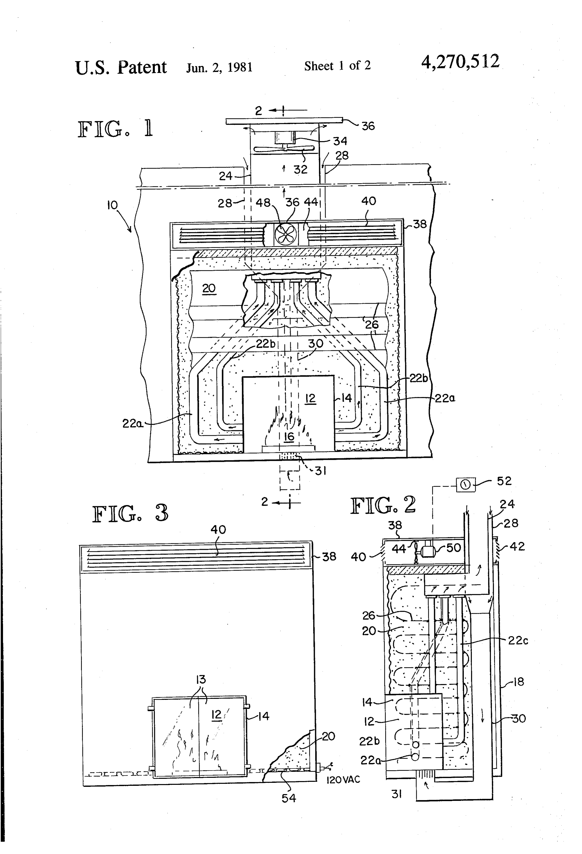
BACKGROUND OF THE INVENTION while thermally isolating the exhaust outlet from the 1. Field of the Invention surrounding support structure. This invention relates to heating systems, and more BRIEF DESCRIPTION OF THE FIGURES OF particularly, to a heating system for producing heat THE DRAWING over a relatively short period and for subsequently uti lizing the heat as desired over a relatively long period. 10 FIG. 1 is a front elevational view of one embodiment 2. Description of the Prior Art of the heat storing fireplace.
With the increasing cost of energy, it has become FIG. 2 is a cross-sectional view of the heat storing increasingly important to utilize energy efficiently. One fireplace taken along the line 1-1 of FIG. 2. common heat producing device is a fireplace which FIG. 3 is a front elevational view of the fireplace of generates a large amount of heat at a fairly low cost. 15 FIG. 1 showing an electrical heating element embedded One problem with the conventional fireplace which in the heat storage medium.
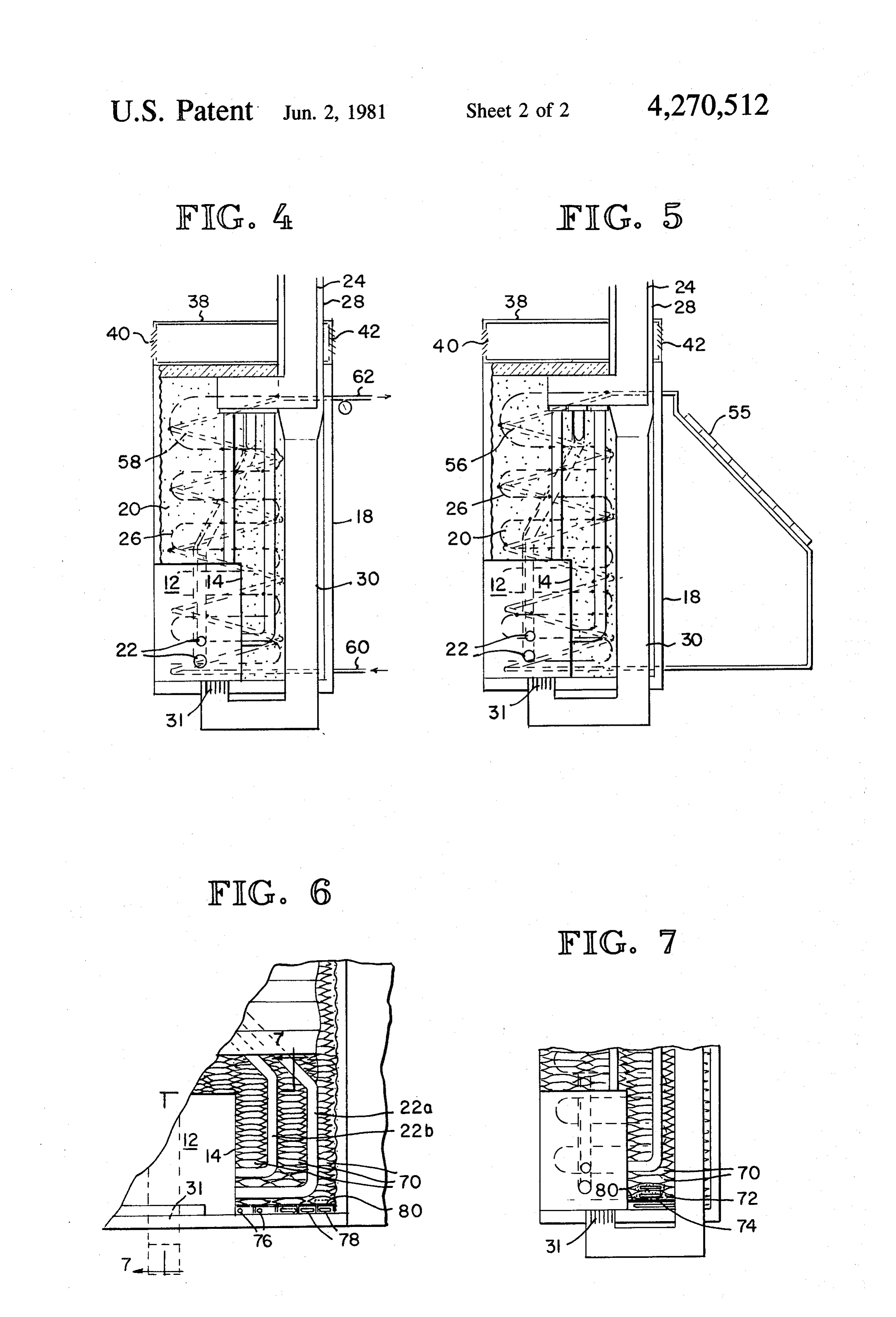
reduces its efficiency and makes it impractical for sus FIG. 4 is a cross-sectional view illustrating the heat tained heating is the difficulty of regulating the heat exchanger of a hot water heating system embedded in output. The heat from the fireplace is generally an al the heat storage medium.
most instantaneous function of the magnitude of the fire FIG. 5 is a cross-sectional view illustrating the heat in the fireplace. Consequently, in order to maintain the 20 exchanger of a solar heating system embedded in the heat from a fireplace at a predetermined level, it is nec heat storage medium.
essary to constantly add fuel to the fire, a requirement FIG. 6 is a front elevational view of another embodi which is not often practical. Also, too much fuel is ment of the heat storing fireplace.
frequently added to the fire which is very wasteful of 25 FIG. 7 is a cross-sectional view of the heat storage heat. fireplace taken along the line 7-7 of FIG. 6. w Another problem which prevents the optimum utili zation of energy is the fluctuating demand for energy. DETALED DESCRIPTION OF THE Often there is sufficient or even an excess of electrical PREFERRED EMBODEMENT or solar power available during certain periods of the day, but such surplus may not be available when the 30 andThe heat storing fireplace as illustrated in FIGS. 1 need for energy is at its peak. This problem greatly firebox 14 whicha may 2 includes combustion area 12 surrounded by a be fabricated by welding sheets of increases the cost of energy since, in the case of electri cal energy, sufficient capital equipment must be pro heavy steel plate in an appropriate manner. The front vided to provide the required power during peak loads. opening of the fire-box 14 is preferably covered by 35 conventional glass fireplace doors 13 as illustrated in
SUMMARY OF THE INVENTION FIG. 3. The fire-box 14 is surrounded by a heat storage It is an object of this invention to provide a means for topmedium which may be an enclosure 18 having an open storing heat produced in a fireplace in order to limit the which contains a material 20 having a high specific heat output from the fireplace while allowing the heat heat such as sand or gravel. The enclosure 18 can be to be slowly dissipated. 40 formed of a variety of materials, but one operative em It is another object of the invention to consume en bodiment utilizes a layer of fire-clay slurry coating both ergy during periods of peak availability while utilizing sides of a metal lath framework. The metal lath frame heat transformed from the energy during periods of work is preferably welded to the fire-box 14 before relative unavailability. being coated with slurry. The inner surfaces of the These and other objects of the invention are accom 45 enclosure are preferably covered with a heavy asbestos plished by a heat storing fireplace having a fire box fibre insulative coating to prevent heat from escaping surrounded by a heat storage medium having a rela therethrough. Alternatively, the entire fireplace may be tively high specific heat. In one embodiment the heat formed by stacking a large number of heat conductive storage medium is a material having a high specific heat bags filled with a high specific heat material such as surrounded by an enclosure. In another embodiment the 50 sand in a rectangular configuration. storage medium is a large number of heat conducting Exhaust gases from the burning fuel 16 flow from the bags containing a high specific heat material. Exhaust combustion area 12 through a plurality of conduits 22 gases from the burning fuel in the fire box flow through extending from the fire box 14 to a vertical exhaust a plurality of conduits positioned between the fire box outlet 24. The conduits 22 are of heat conducting mate and a common exhaust outlet. The conduits are posi 55 rial so that heat from the exhaust gases is transferred to tioned along circuitous routes to distribute heat within the material 20. The inside diameters of the conduits 22 the storage medium and further distribution is provided are selected to equalize the flow of exhaust gases by a heat conducting lattice interconnecting the con through the respective conduits 22. Thus, for example, duits and extending through the storage medium in a the flow of exhaust gases through the upper conduits circuitous path. The upper portion of the enclosure is 60 22b would ordinarily be greater than the flow of ex selectively vented in order to dissipate heat from the haust gases through the lower conduits 22a since the storage medium to the surroundings so that the heat exhaust gases entering the upper conduit 22b are hotter output from the burning fuel is limited by the insulative and exhaust conduit 22b is shorter than conduit 22a. effect of the storage medium, and the heat from the However, since conduit 22b has a smaller inside diame burning fuel may be dissipated over a relatively long 65 ter than conduit 22a, the flow of exhaust gases through period. The draft in the fireplace is created by an air both pairs of conduits 22a, b are equal. As best illus conveying means drawing exhaust gases through the trated in FIG. 2, the heat from the conduits 22 is further exhaust outlet, and the sizes of the conduits are adjusted distributed in the material 20 by a heat conducting lat
Page 5
tice 26 extending through the material 29 in a circuitous heat stored in the material 20 is then utilized during the path. The lattice 26 is secured to the conduits 22 in a evening hours or on cloudy days.
suitable manner such as by welding. Although the primary mechanism for removing heat Combustion air is conveyed to the combustion area stored in the material 20 is the plenum 38, the heat 12 through an inlet jacket 23 surrounding the exhaust 5 storing fireplace () may also be utilized to directly heat outlet 24 and an inlet duct 3. The inlet duct 30 termi cold water in a hot water heating system. As illustrated nates in a grate 31 on the floor of the fire-box 34. As in FIG. 4, a heat exchanger 58, which is preferably combustion air flows through the inlet jacket 28 it ab connected to the heat conducting lattice 26, is embed sorbs heat from the exhaust gases in the exhaust outlet ded in the material. 20. One end of the heat exchanger 58 24 so that the combustion air is pre-warmed before O is connected to the cold water supply line 10 while the entering the combustion area A2. Additionally, the inlet outlet is connected to the hot water distribution system jacket thoroughly isolates the exhaust outlet 24 from the 62. Similarly, heat from a solar heat collector 55 may be surrounding support structure. Since the conduits 22 transferred to the material 20 by a liquid recirculating intersect the fire-box 24 on the horizontal, and because through heat exchange tubes 56. of the additional drag created by the relatively narrow In an alternative embodiment of the heat storing fire conduits 22, an exhaust fan 32 driven by a conventional place, as illustrated in FIGS. 6 and 7, the heat storage motor 34 is provided to create a draft through the con medium is a large number of bags 70 containing a mate bustion area. 2. The fan 32, notor 34, exhaust outlet 24 rial 72 having a high specific heat. The bags 70 are of a and inlet jacket 23 are covered by a small roof 36 to conductive material such a metallic foil which may be shield these components from moisture. 20 anodized or otherwise color treated on one surface to
Heat stored in the material 20 siowly dissipates efficiently absorb heat and radiate it to the material 72. through a rectangular plenunn 38 covering the enclo sure 8. As best illustrated in FIG. 2, the plenum is The sizes of the bags 70 may vary depending upon their formed by a pair of louvered sidewalls 40, 42 which are construct For position.
the example, large size bags may be used to floor, top and sides while smaller bags separated from each other by a baffle 44. The baffle 44 25 may be used internally.
contains an opening 46 therethrough, and a fan 48 As best illustrated in FIG. 7, metallic honeycomb driven by a motor 50 is nounted in the opening 46 to assemblies convey air into the plenum 33 through louver 40 where material 72 74 may be inserted in the bags 70 with the to greatly improve the heat transfer charac it is heated and out louver 42. if desired, the motor 50 may be actuated by a conventionai thermostat 52 when teristics from the bags 70 to the material 72. The remaining components of the fireplace are as the temperature in the surrounding area fallis below a preset value. illustrated in FGS. 1-5. The exception is that heating In operation, fuel 16 Such as wood, coal, oil or gas is elements 76 corresponding to the heating coils 54 (FIG. burned in the fire-box 14. As the exhaust gases flow 3), and heat exchanger tubes 78 corresponding to the through the conduits 22 and exhaust outlet 24 heat is 35 tubes 56 (FIG. 5) and 58 (FIG. 4) are placed within transferred to the material 20 by the conduits 22 and the metal tunnels 80 at the bottom of the fireplace. This heat conducting attice 26. The material 20 regulates the construction facilitates replacement of the heating ele peak temperature from the burning fuel 6 while storing ments 76 and heat exchanger tubes 78 without removing the heat for subsequent use. At the same time, combus the bags 70.
tion air entering the fire-box 14 through the inlet jacket 40 The heat storing fireplace of the present invention is 28 and duct 3G is pre-warned. When the fire in the thus capable of efficiently storing heat generated under fire-box 4 is subsequently extinguished, the heat stored optimum conditions for relatively slow utilization over in the material 20 is slowly dissipated by air flowing a fairly long period of time.
through the plenum 33 when the motor 5C is actuated. claim:
Of course, the motor 50 may also be actuated when fuel 45 ii. A heat storing fireplace, comprising: 16 is being burned in the fire-box 4. a firebox at least partially enclosing a cornbustion The inventive heat storing fireplace may also be uti area;
lized to consume electrical power during off-peak peri a heat storage medium having a relatively high spe ods for subsequent utilization of the electrically pro cific heat surrounding said firebox, said heat stor duced heat during peak power periods as illustrated in 50 age medium including a plurality of heat conduc FIG. 3. For this purpose, an electrical heating coil 54 of tive bags containing a material having a high spe conventional variety is embedded in the material 20 cific heat;
along the botton of the enclosure i8 and connected to an exhaust outlet extending upwardly above said the heat dissipating lattice 26. During periods of low storage medium;
power consumption when power is relatively inexpen a plurality of heat conducting conduits positioned sive the heating element 54 may be utilized to heat the between said firebox and exhaust outlet in a circu material 20. Thereafter, the heat produced by the heat itous route within said heat storage medium with ing element 54 during off-peak power periods is subse said heat conductive bags stacked around said fire quently dissipated during periods where power is rela box and said heat conducting conduits such that tively expensive. The heat storing fireplace may also be 60 heat from exhaust gases flowing through said con used to store heat generated by a conventional solar duits is stored in said heat storage medium; and heat collector as illustrated in FIG. 5. The heat collec ventiation means allowing heat transfer from said to 55 is connected to a heat exchanger 56 which is storage medium such that heat may be generated embedded in the naterial 20 aiong the bottom of the during a relatively brief period and utilized over a enclosure 18 to supply heat to the material 20 during relatively long period.
daylight hours, The heat exchanger 56 is preferably 2. The heat storing fireplace of claim 1 wherein the connected to tie heat conductive lattice 26 in order to surfaces of Said bags are color treated to efficiently better distribute heat throughout the material 20. The absorb heat and radiate heat to said material.
Page 6
3. The heat storing fireplace of claim 1 wherein said bags contain a heat conductive honeycomb assembly bags are stacked on a plurality of heat conductive tun nels each of which surround a heat transfer element to with said material for improving the heat transfer char-, . allow removal of said heat transfer element without removing said bags. 5 acteristics from said bags to said material. 4. The heat storing fireplace of claim 1 wherein said k k k k sk
Provenance
- Collection
- Cited prior art
- Original PDF
- patentimages.storage.googleapis.com →
- Filed
- 1978-03-06
- Pages
- 6
- Method
- pdftotext (the PDF's own text layer) + pdftoppm 300dpi page scans
- Source
- Google Patents bibliographic record
- Granted
- 1981-06-02
- Inventors
- Robert E. Van Der Maas
- Transcribed from
- patentimages.storage.googleapis.com →