patent · US5279260
Water fuelled boiler
18 January 1994
Page 1 — bibliographic record
IHHHHHHHHHHIII
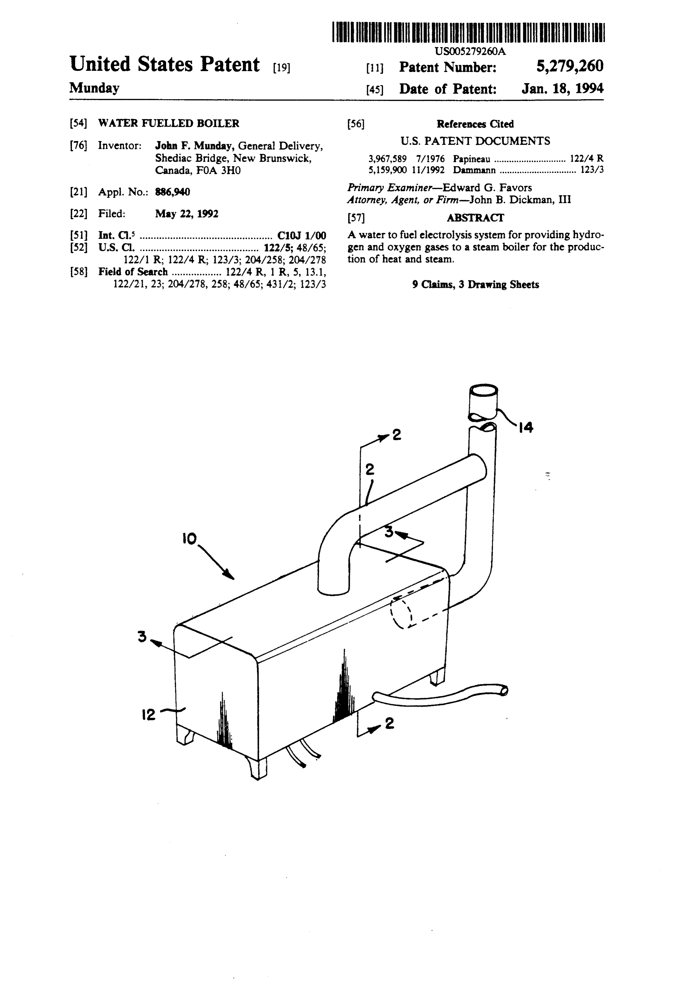
United States Patent (19) 11 Patent Number: 5,279,260 Munday (45) Date of Patent: Jan. 18, 1994 54) WATER FUELLED BOILER (56) References Cited 76 Inventor: John F. Munday, General Delivery, U.S. PATENT DOCUMENTS Shediac Bridge, New Brunswick, 3,967,589 7/1976 Papineau ............................. 122/4. R Canada, FOA 3HO 5,159,900 1/1992 Damnann ............................... 123A3 (21) Appl. No.: 886,940 Primary Examiner-Edward G. Favors Attorney, Agent, or Firm-John B. Dickman, III 22 Filed: May 22, 1992 57 ABSTRACT (51) Int. C. ................................................ C10 1/00 A water to fuel electrolysis system for providing hydro 52 U.S. C. ........................................... 122/5; 48/65; gen and oxygen gases to a steam boiler for the produc 122/1 R; 122/4 R; 123/3; 204/258; 204/278 tion of heat and steam.
122/21, 23; 204/278, 258; 4.8/65; 431/2; 123/3 9 Claims, 3 Drawing Sheets
Page 2
Drawing sheet — no readable text.
Page 3
Drawing sheet — no readable text.
Page 4
Drawing sheet — no readable text.
Page 5
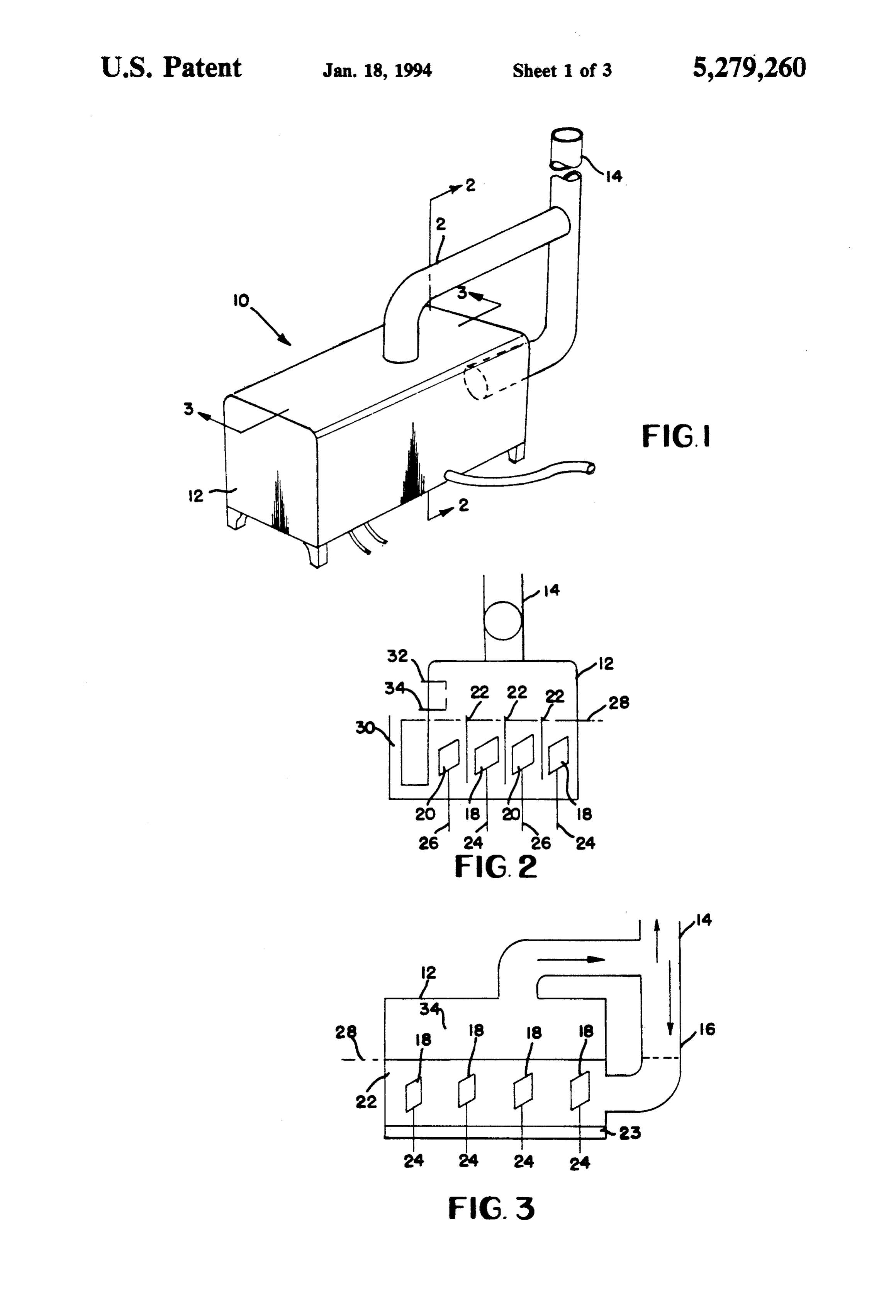
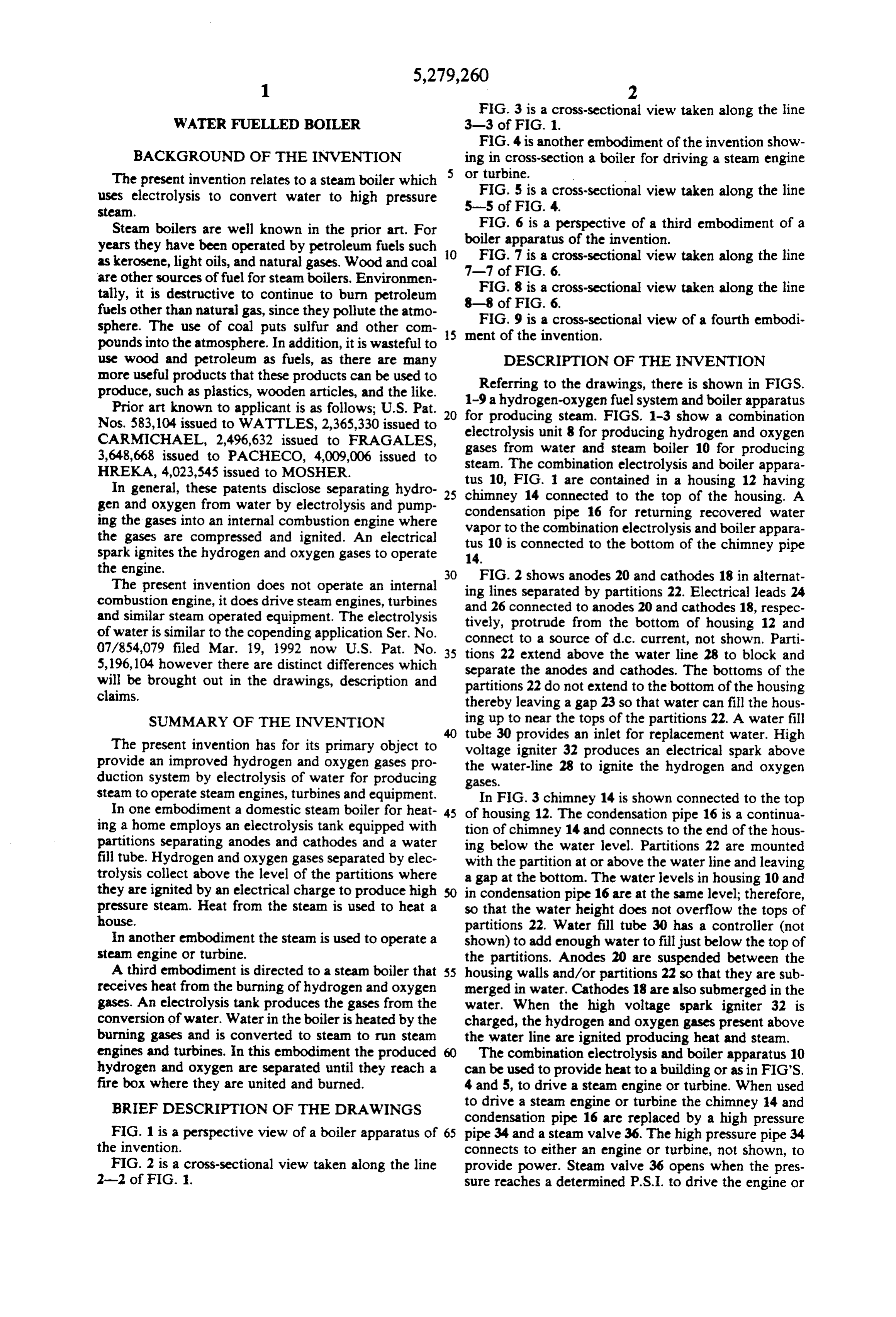
FIG. 3 is a cross-sectional view taken along the line
WATER FUELLED BOLER 3-3 of FIG. 1.
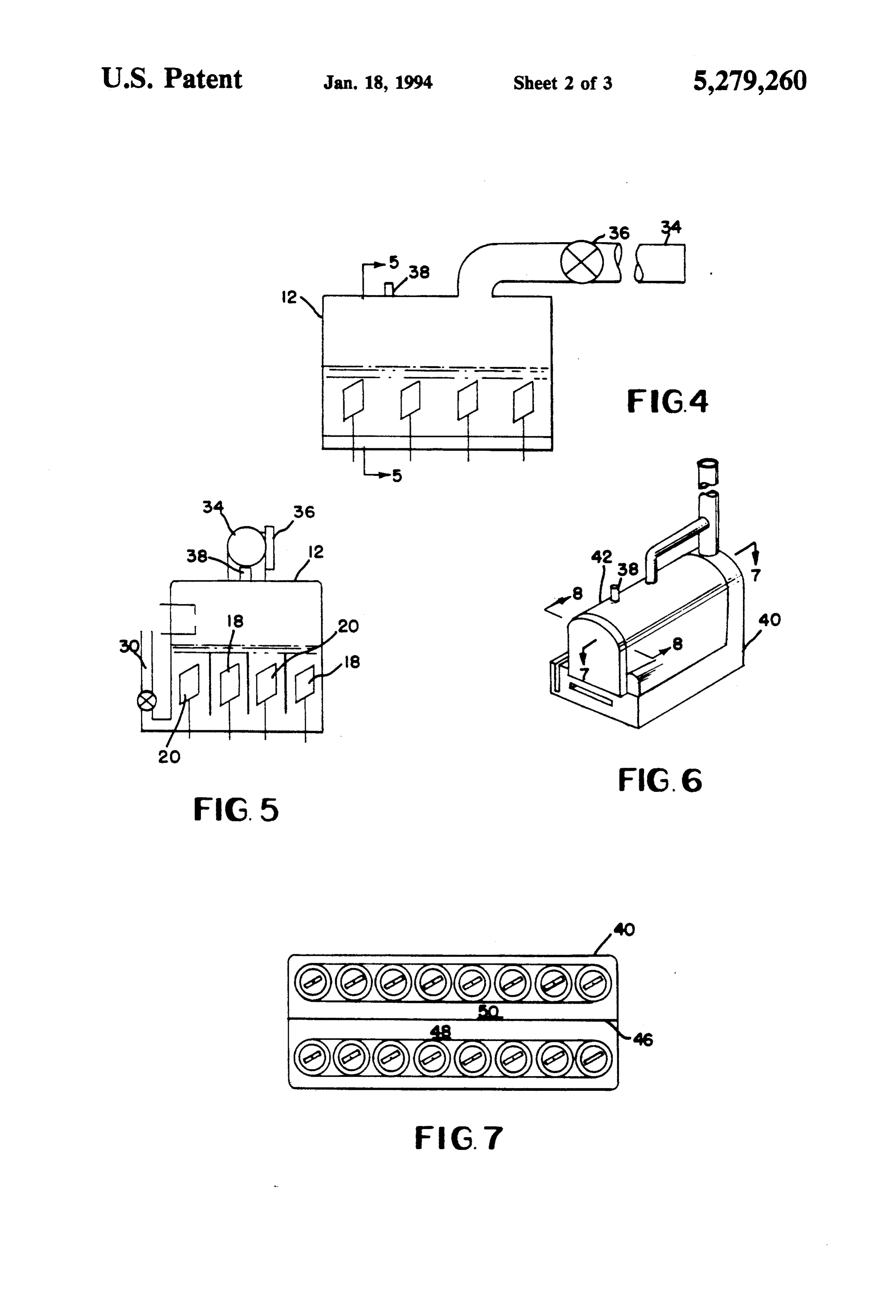
FIG. 4 is another embodiment of the invention show
BACKGROUND OF THE INVENTION ing in cross-section a boiler for driving a steam engine The present invention relates to a steam boiler which 5 or turbine. -
uses electrolysis to convert water to high pressure 5-5 FIG. 5 is a cross-sectional view taken along the line steam. of FIG. 4.
FIG. 6 is a perspective of a third embodiment of a
Steam boilers are well known in the prior art. For boiler apparatus years they have been operated by petroleum fuels such 10 of the invention. FIG. 7 is a cross-sectional view taken along the line as kerosene, light oils, and natural gases. Wood and coal 7-7 are other sources of fuel for steam boilers. Environmen of FIG. 6.
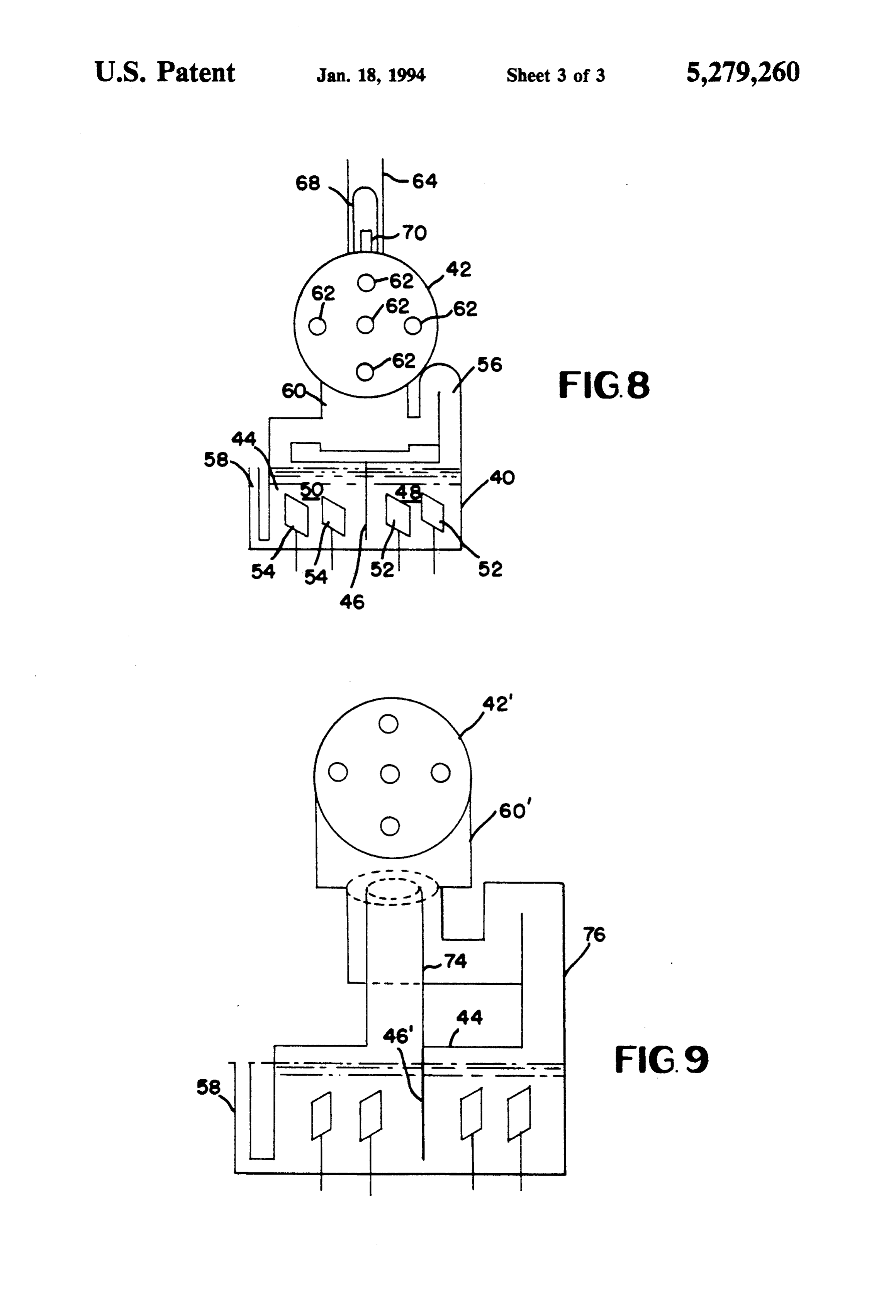
tally, it is destructive to continue to burn petroleum FIG. 8 is a cross-sectional view taken along the line fuels other than natural gas, since they pollute the atmo 88 of FIG. 6.
sphere. The use of coal puts sulfur and other com 15 ment of9theis ainvention.
FIG. cross-sectional view of a fourth embodi pounds into the atmosphere. In addition, it is wasteful to use wood and petroleum as fuels, as there are many DESCRIPTION OF THE INVENTION more useful products that these products can be used to produce, such as plastics, wooden articles, and the like. 1-9Referring to the drawings, there is shown in FIGS. ahydrogen-oxygen fuel system and boiler apparatus
Prior art known to applicant is as follows; U.S. Pat. 20 for producing steam. FIGS. 1-3 show a combination Nos. 583,104 issued to WATTLES, 2,365,330 issued to electrolysis unit 8 for producing hydrogen and oxygen CARMICHAEL, 2,496,632 issued to FRAGALES, gases from water and steam boiler 10 for producing 3,648,668 issued to PACHECO, 4,009,006 issued to steam. The combination electrolysis and boiler appara HREKA, 4,023,545 issued to MOSHER.
In general, these patents disclose separating hydro 25 tus 10, FIG. are contained in a housing 12 having gen and oxygen from water by electrolysis and pump chimney 14 connected to the top of the housing. A ing the gases into an internal combustion engine where condensation vapor to the pipe 16 for returning recovered water combination electrolysis and boiler appara the gases are compressed and ignited. An electrical spark ignites the hydrogen and oxygen gases to operate tus 14.
10 is connected to the bottom of the chimney pipe the engine. 30 FIG. 2 shows anodes 20 and cathodes 18 in alternat The present invention does not operate an internal ing lines separated by partitions 22. Electrical leads 24 combustion engine, it does drive steam engines, turbines and 26 connected to anodes 20 and cathodes 18, respec and similar steam operated equipment. The electrolysis of water is similar to the copending application Ser. No. tively, protrude from the bottom of housing 12 and connect to a source of d.c. current, not shown. Parti 07/854,079 filed Mar. 19, 1992 now U.S. Pat. No. 35 tions 22 extend above the water line 28 to block and 5,196,104 however there are distinct differences which separate the anodes and cathodes. The bottoms of the will be brought out in the drawings, description and partitions 22 do not extend to the bottom of the housing claims. thereby leaving a gap 23 so that water can fill the hous SUMMARY OF THE INVENTION ing up to near the tops of the partitions 22. A water fill tube 30 provides an inlet for replacement water. High
The present invention has for its primary object to voltage igniter 32 produces an electrical spark above provide an improved hydrogen and oxygen gases pro the water-line 28 to ignite the hydrogen and oxygen duction system by electrolysis of water for producing gases.
steam to operate steam engines, turbines and equipment. In FIG. 3 chimney 14 is shown connected to the top In one embodiment a domestic steam boiler for heat 45 of housing 12. The condensation pipe 16 is a continua ing a home employs an electrolysis tank equipped with tion of chimney 14 and connects to the end of the hous partitions separating anodes and cathodes and a water fill tube. Hydrogen and oxygen gases separated by elec ing below the water level. Partitions 22 are mounted with the partition at or above the water line and leaving trolysis collect above the level of the partitions where a gap at the bottom. The water levels in housing 10 and they are ignited by an electrical charge to produce high SO in condensation pipe 16 are at the same level; therefore, pressure steam. Heat from the steam is used to heat a so that the water height does not overflow the tops of house. partitions 22. Water fill tube 30 has a controller (not In another embodiment the steam is used to operate a shown) to add enough water to fill just below the top of steam engine or turbine. the partitions. Anodes 20 are suspended between the A third embodiment is directed to a steam boiler that 55 housing walls and/or partitions 22 so that they are sub receives heat from the burning of hydrogen and oxygen merged in water. Cathodes 18 are also submerged in the gases. An electrolysis tank produces the gases from the water. When the high voltage spark igniter 32 is conversion of water, Water in the boiler is heated by the charged, the hydrogen and oxygen gases present above burning gases and is converted to steam to run steam the water line are ignited producing heat and steam. engines and turbines. In this embodiment the produced The combination electrolysis and boiler apparatus 10 hydrogen and oxygen are separated until they reach a can be used to provide heat to a building or as in FIG'S. fire box where they are united and burned. 4 and 5, to drive a steam engine or turbine. When used BRIEF DESCRIPTION OF THE DRAWINGS to drive a steam engine or turbine the chimney 14 and condensation pipe 16 are replaced by a high pressure
FIG. 1 is a perspective view of a boiler apparatus of 65 pipe 34 and a steam valve 36. The high pressure pipe 34 the invention. connects to either an engine or turbine, not shown, to FIG. 2 is a cross-sectional view taken along the line provide power. Steam valve 36 opens when the pres 2-2 of FIG. 1. sure reaches a determined P.S.I. to drive the engine or
Page 6
turbine. Should the pressure exceed the rated P.S.I. for portant that one should study the drawings, description the housing 12 a safety valve 38 opens to relieve excess and claims for a complete understanding of the inven pressure. tion,
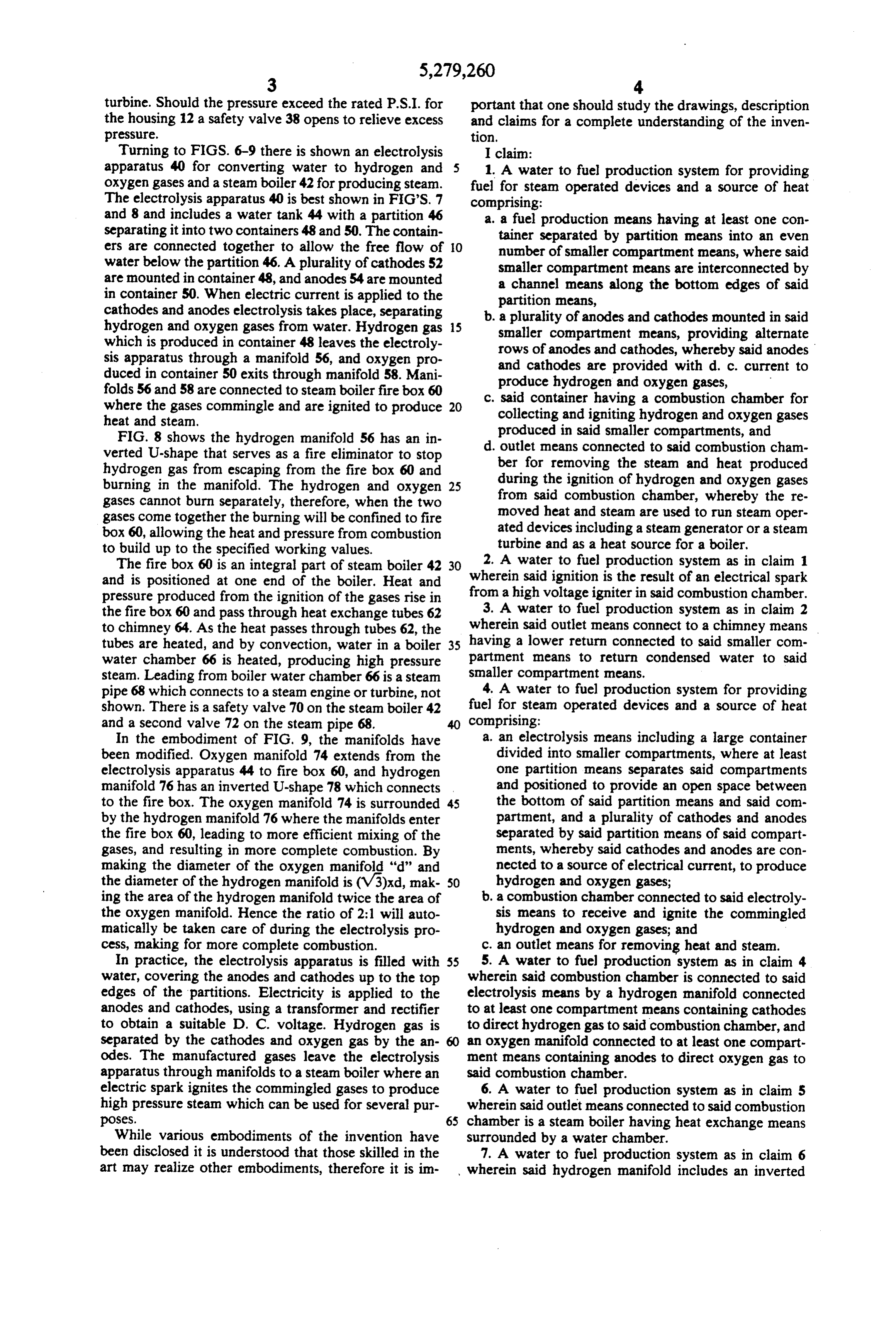
Turning to FIGS. 6-9 there is shown an electrolysis I claim:
apparatus 40 for converting water to hydrogen and 1. A water to fuel production system for providing oxygen gases and a steam boiler 42 for producing steam. fuel for steam operated devices and a source of heat The electrolysis apparatus 40 is best shown in FIGS. 7 comprising:
and 8 and includes a water tank 44 with a partition 46 a. a fuel production means having at least one con separating it into two containers 48 and 50. The contain tainer separated by partition means into an even ers are connected together to allow the free flow of 10 number of smaller compartment means, where said water below the partition 46. A plurality of cathodes 52 smaller compartment means are interconnected by are mounted in container 48, and anodes 54 are mounted a channel means along the bottom edges of said in container 50. When electric current is applied to the partition means, cathodes and anodes electrolysis takes place, separating b. a plurality of anodes and cathodes mounted in said hydrogen and oxygen gases from water. Hydrogen gas 15 smaller compartment means, providing alternate which is produced in container 48 leaves the electroly rows of anodes and cathodes, whereby said anodes sis apparatus through a manifold 56, and oxygen pro and cathodes are provided with d. c. current to duced in container 50 exits through manifold 58. Mani produce hydrogen and oxygen gases, folds 56 and 58 are connected to steam boiler fire box 60 where the gases commingle and are ignited to produce 20 c. said container having a combustion chamber for heat and steam. collecting and igniting hydrogen and oxygen gases FIG. 8 shows the hydrogen manifold 56 has an in produced in said smaller compartments, and d. outlet means connected to said combustion cham verted U-shape that serves as a fire eliminator to stop ber for removing the steam and heat produced hydrogen gas from escaping from the fire box 60 and during the ignition of hydrogen and oxygen gases burning in the manifold. The hydrogen and oxygen 25 from said combustion chamber, whereby the re gases cannot burn separately, therefore, when the two gases come together the burning will be confined to fire moved heat and steam are used to run steam oper box 60, allowing the heat and pressure from combustion ated devices including a steam generator or a steam to build up to the specified working values. turbine and as a heat source for a boiler. The fire box 60 is an integral part of steam boiler 42 30 2. A water to fuel production system as in claim 1 and is positioned at one end of the boiler. Heat and wherein said ignition is the result of an electrical spark pressure produced from the ignition of the gases rise in from a high voltage igniter in said combustion chamber. the fire box 60 and pass through heat exchange tubes 62 3. A water to fuel production system as in claim 2 to chimney 64. As the heat passes through tubes 62, the wherein said outlet means connect to a chimney means tubes are heated, and by convection, water in a boiler 35 having a lower return connected to said smaller com water chamber 66 is heated, producing high pressure partment means to return condensed water to said steam. Leading from boiler water chamber 66 is a steam smaller compartment means.
pipe 68 which connects to a steam engine or turbine, not 4. A water to fuel production system for providing shown. There is a safety valve 70 on the steam boiler 42 fuel for steam operated devices and a source of heat and a second valve 72 on the steam pipe 68. comprising:
In the embodiment of FIG, 9, the manifolds have a. an electrolysis means including a large container been modified. Oxygen manifold 74 extends from the divided into smaller compartments, where at least electrolysis apparatus 44 to fire box 60, and hydrogen one partition means separates said compartments manifold 76 has an inverted U-shape 78 which connects and positioned to provide an open space between to the fire box. The oxygen manifold 74 is surrounded 45 the bottom of said partition means and said com by the hydrogen manifold 76 where the manifolds enter partment, and a plurality of cathodes and anodes the fire box 60, leading to more efficient mixing of the separated by said partition means of said compart gases, and resulting in more complete combustion. By ments, whereby said cathodes and anodes are con making the diameter of the oxygen manifold "d" and nected to a source of electrical current, to produce the diameter of the hydrogen manifold is (V3)xd, mak 50 hydrogen and oxygen gases; ing the area of the hydrogen manifold twice the area of . a combustion chamber connected to said electroly the oxygen manifold. Hence the ratio of 2:1 will auto sis means to receive and ignite the commingled matically be taken care of during the electrolysis pro hydrogen and oxygen gases; and cess, making for more complete combustion. c. an outlet means for removing heat and steam. In practice, the electrolysis apparatus is filled with 55 5. A water to fuel production system as in claim 4 water, covering the anodes and cathodes up to the top wherein said combustion chamber is connected to said edges of the partitions. Electricity is applied to the electrolysis means by a hydrogen manifold connected anodes and cathodes, using a transformer and rectifier to at least one compartment means containing cathodes to obtain a suitable D. C. voltage. Hydrogen gas is to direct hydrogen gas to said combustion chamber, and separated by the cathodes and oxygen gas by the an an oxygen manifold connected to at least one compart odes. The manufactured gases leave the electrolysis ment means containing anodes to direct oxygen gas to apparatus through manifolds to a steam boiler where an said combustion chamber.
electric spark ignites the commingled gases to produce 6. A water to fuel production system as in claim 5 high pressure steam which can be used for several pur wherein said outlet means connected to said combustion poses. 65 chamber is a steam boiler having heat exchange means While various embodiments of the invention have surrounded by a water chamber.
been disclosed it is understood that those skilled in the 7. A water to fuel production system as in claim 6 art may realize other embodiments, therefore it is im wherein said hydrogen manifold includes an inverted
Page 7
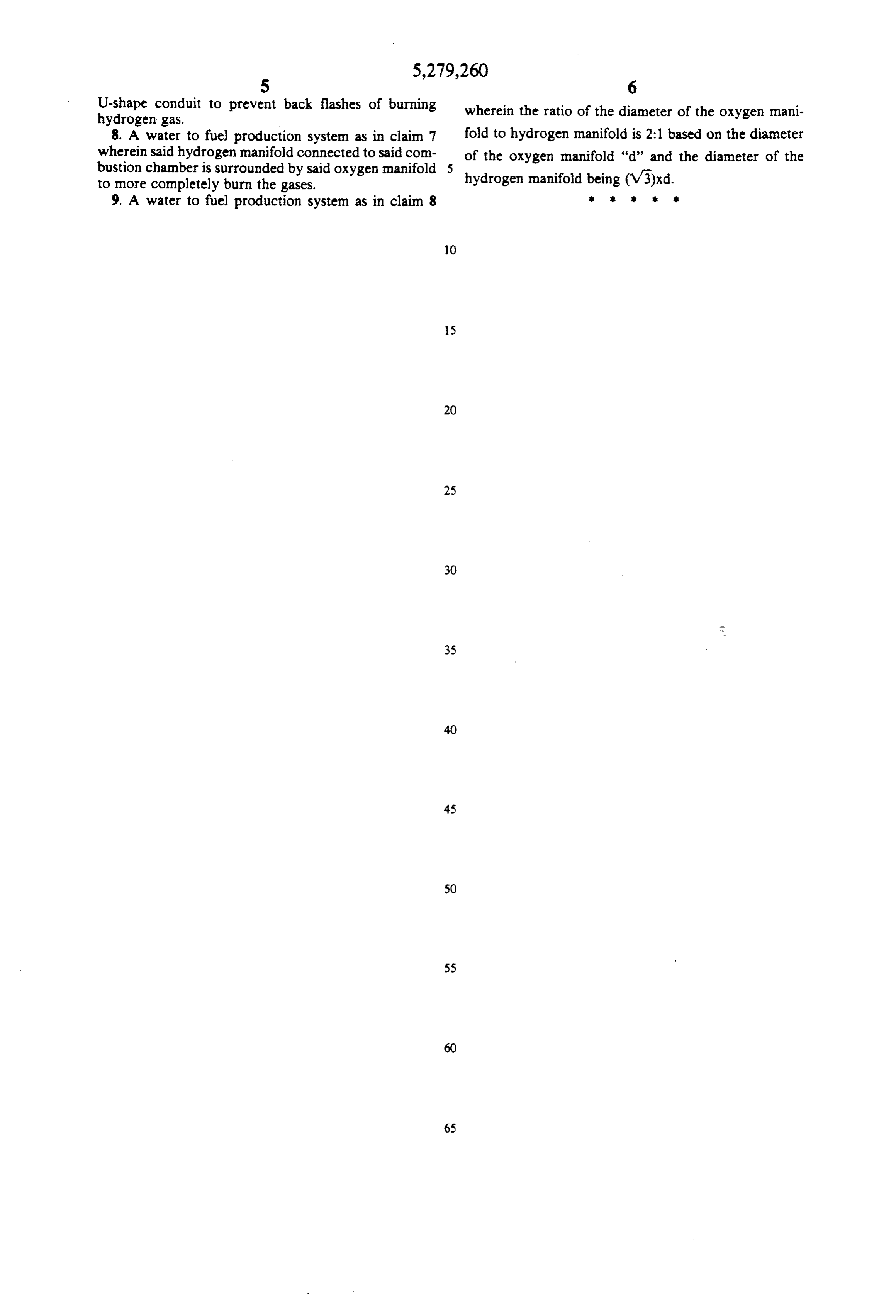
U-shape conduit to prevent back flashes of burning wherein the ratio of the diameter of the oxygen mani hydrogen gas.
8. A water to fuel production system as in claim 7 fold to hydrogen manifold is 2:1 based on the diameter wherein said hydrogen manifold connected to said com- of the oxygen manifold "d' and the diameter of the bustion chamber is surrounded by said oxygen manifold 5 to more completely burn the gases. hydrogen manifold being (V3)xd. 9. A water to fuel production system as in claim 8 k . . .
Provenance
- Collection
- Cited prior art
- Original PDF
- patentimages.storage.googleapis.com →
- Filed
- 1992-05-22
- Pages
- 7
- Method
- pdftotext (the PDF's own text layer) + pdftoppm 300dpi page scans
- Source
- Google Patents bibliographic record
- Granted
- 1994-01-18
- Inventors
- John F. Munday
- Transcribed from
- patentimages.storage.googleapis.com →