patent · US5275150
Solar collector
4 January 1994
Page 1 — bibliographic record
O USOO52751SOA
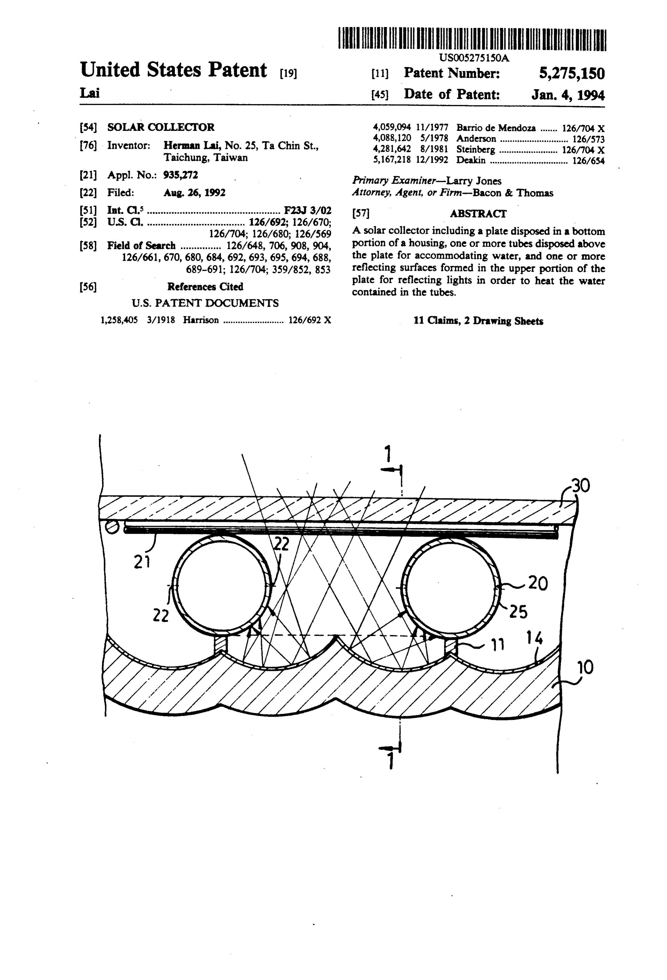
United States Patent (19) (11) Patent Number: 5,275,150 Lai 45) Date of Patent: Jan. 4, 1994 54). SOLAR COLLECTOR 4,059,094 11/1977 Barrio de Mendoza ....... 126/704X 4,088,120 5/1978 Anderson ............................ 126/573 76) Inventor: Herman Lai, No. 25, Ta Chin St., 4,281,642 8/1981 Steinberg. Taichung, Taiwan 5,167,218 12/1992 Deakin ................................ 126/654 (21) Appl. No.: 935,272 Primary Examiner-Larry Jones (22 Filed: Aug. 26, 1992 Attorney, Agent, or Firm-Bacon & Thomas 51) Int. C.’............................................... (57 ABSTRACT 52 U.S. C. .......................126/704. g f's A solar collector including a plate disposed in a bottom (58) Field of Search ............... 126/6,706,908,904, portion of a housing, one or more tubes disposed above 126/661, 670, 680, 684, 692, 693,695, 694, 688, the plate for accommodating water, and one or more 689-691; 126/704; 359/852, 853 reflecting surfaces formed in the upper portion of the (56) Refeferences Cited plate for reflecting lights in order to heat the water contained in the tubes.
1,258,405 3/1918 Harrison ......................... 126/692 X 11 Claims, 2 Drawing Sheets
Page 2
Drawing sheet — no readable text.
Page 3
Drawing sheet — no readable text.
Page 4
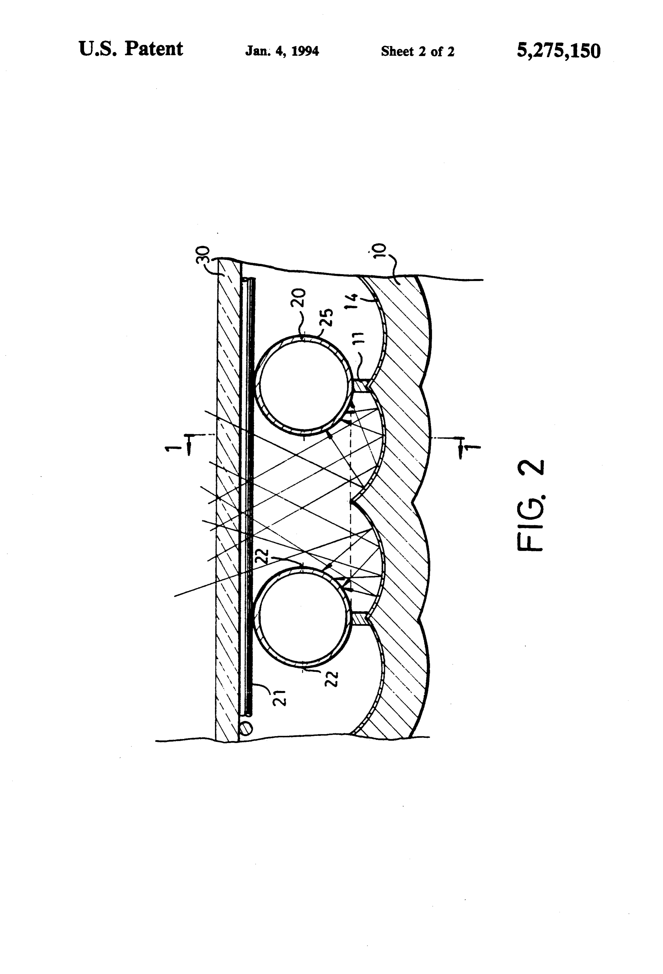
tween every two adjacent tubes 20, and one reflective
SOLAR COLLECTOR surface provided on each side of each of the tubes 20, and the center of curvature of each of the concave
BACKGROUND OF THE INVENTION surfaces is preferably located at the side portions 22 of 1. Field of the Invention the tubes 20, such that the light reflected by the reflec The present invention relates to a solar collector. tive surfaces 14 may be concentrated on the tubes 20 2. Description of the Prior Art and such that the water flowing through the tubes 20 A typical solar collector is shown in FIG.3 and com can be heated in a fast speed.
prises a layer of heat insulating materials 60 disposed in O It is preferable that the outer peripheral surfaces of the bottom portion of a housing 80, a sheet 90, which is the tubes 20 are electroplated with a layer of chrome preferably made of glass, disposed on top of the housing coating 25 in order to facilitating the absorption of the 80, a layer of tin foil 70 applied to the top of the materi heat from the light, in which the chrome coating 25 has als 60, a plurality of brass tubes 40 disposed above the a black color.
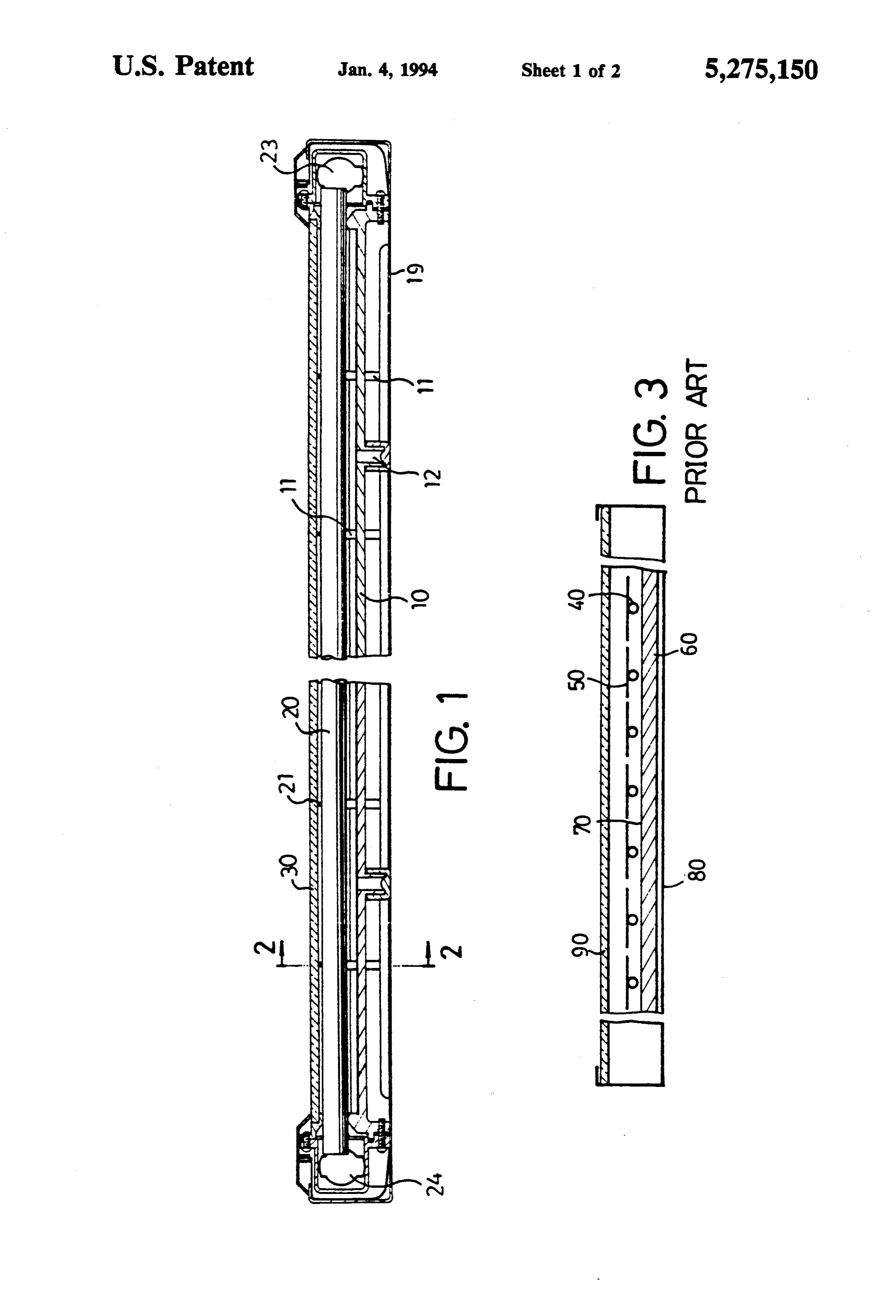
tin foil 70 and each including a heat collector plate 50 15 Referring again to FIG. 1, at least one opening 12 is disposed thereon for collecting solar energy and for provided for vacuuming the space of the housing 19 heating the water flowing through the tubes 40. The formed between the plate 10 and the cover 30, and the Solar energy can not be suitably collected. opening 12 is blocked after vacuuming operations such The present invention has arisen to mitigate and/or that the space formed between the plate 10 and the obviate the afore-described disadvantages of the con cover 30 is a vacuum space, whereby, no media for ventional solar collectors. 20 conducting heat is existed in the space, such that no heat
SUMMARY OF THE INVENTION loss of the water will be occurred, in addition, the plate The primary objective of the present invention is to heated 10 and the cover 30 for forming the space will not be provide a solar collector which has a high energy col be madesuch of that the plate 10 and the cover 30 need not heat resistant materials. The mesh grid 21 is lecting rate. 25 provided to support the cover 30 when the space is
In accordance with one aspect of the invention, there vacuumed.
is provided a solar collector comprising a housing, a Accordingly, the solar energy can be effectively col plate disposed in a bottom portion of the housing and lected including at least one reflecting surface formed in an presentbyinvention. the solar collector in accordance with the upper portion thereof, and at least one tube disposed 30 Although this invention has been described with a above the plate for accommodating heat conducting certain degree of particularity, it is to be understood medium, whereby, light shining on the reflecting sur face is reflected to the tube in order to heat the heat that the present disclosure has been made by way of conducting medium. example only and that numerous changes in the detailed Further objectives and advantages of the present 35 construction and the combination and arrangement of invention will become apparent from a careful reading parts may be resorted to without departing from the of the detailed description provided hereinbelow, with spirit and scope of the invention as hereinafter claimed. I claim:
appropriate reference to the accompanying drawings.
1. A solar collector comprising: a housing; a plate
BRIEF DESCRIPTION OF THE DRAWINGS disposed in a bottom portion of said housing and having FIG. 1 is a cross sectional view of a solar collector in a plurality of concave and reflecting surfaces formed in accordance with the present invention, taken along an upper portion thereof such that adjacent concave lines 1-1 of FIG. 2; and reflecting surfaces define a cusp therebetween; a FIG. 2 is a cross sectional view taken along lines 2-2 tube disposed above and extending along said cusp for of FIG. 1; and 45 accommodating a heat conducting medium therein; FIG. 3 is a partial cross sectional view of the typical and, support means attached to the plate at the cusp to solar collector. support said tube on said plate, whereby, light shining
DETAILED DESCRIPTION OF THE
on said concave and reflecting surfaces is reflected onto
PREFERRED EMBODIMENT said tube in order to heat said heat conducting medium. 2. A solar collector according to claim 1, wherein
Referring to FIGS. 1 and 2, a solar collector in accor said concave and reflecting surfaces include a layer of dance with the present invention comprises generally a silver applied thereon for reflecting said light. plate 10 disposed in the bottom portion of a housing 19, 3. A solar collector according to claim 1 further com a plurality of tubes 20 disposed above the plate 10 and prising a cover engaged on a top portion of aid housing supported in place by posts 11, a mesh grid 21 disposed 55 and arranged such that a space is defined between said above the tubes 20 and a cover 30 disposed above the plate and said cover which space comprises a vacuum mesh grid 21 and preferably made of glass materials; an space.
inlet pipe 23 and an outlet pipe 24 disposed in the hous 4. A solar collector according to claim 3, wherein ing 19 and communicated with the end portions of the said housing further comprises a mesh grid disposed tubes 20 respectively, such that water and the like may between said tubes and said cover for supporting said flow into the outlet pipe 24 via the inlet pipe 23 and the COWe.
tubes 20. 5. A solar collector according to claim 3, wherein Asbest shown in FIG. 2, the plate 10 is wave shaped said housing defines at least one opening therein for including a plurality of concave surfaces formed in the drawing a vacuum in said space. upper portion thereof, each of the concave surfaces has 65 6. A solar collector according to claim 1, further a layer of silver 14 formed thereon by such as electro comprising a chrome coating applied to an outer pe plating processes so as to form a reflective surface, it is ripheral surface of each of said tubes for facilitating heat preferable that two concave surfaces are formed be absorption.
Page 5
7. A solar collector comprising: a housing; a plate and arranged such that a space is defined between said disposed in a bottom portion of said housing and having plate and said cover which space comprises a vacuum a plurality of concave and reflecting surfaces formed in space.
an upper portion thereof such that adjacent concave 9. A solar collector according to claim 8, wherein and reflecting surfaces define a cusp therebetween; a said housing further comprises a mesh grid disposed layer of silver applied to said concave and reflecting between said tubes and said cover for supporting said surfaces; a tube disposed above and extending along coVer, said cusp for accommodating a heat conducting me 10. A solar collector according to claim 8, wherein dium therein; and, support means attached to the plate said housing defines at least one opening formed therein at the cusp to support said tube on said plate, whereby, 10 for drawing a vacuum in said space. light shining on said concave and reflecting surfaces is 11. A solar collector according to claim 7, further reflected onto said tube in order to heat said heat con comprising a chrome coating applied to an outer pe ducting medium. ripheral surface of each of said tubes for facilitating heat 8. A solar collector according to claim 7 further com absorption.
prising a cover engaged on a top portion of said housing 15
Provenance
- Collection
- Cited prior art
- Original PDF
- patentimages.storage.googleapis.com →
- Filed
- 1992-08-26
- Pages
- 5
- Method
- pdftotext (the PDF's own text layer) + pdftoppm 300dpi page scans
- Source
- Google Patents bibliographic record
- Granted
- 1994-01-04
- Inventors
- Herman Lai
- Transcribed from
- patentimages.storage.googleapis.com →