patent · US4737896
Illumination device
12 April 1988
Page 1 — bibliographic record
United States Patent (19) 11 Patent Number: 4,737,896 Mochizuki et al. 45 Date of Patent: Apr. 12, 1988 54 ILLUMINATION DEVICE 58) Field of Search ............... 362/300, 296,299, 30,
75 Inventors: Noritaka Mochizuki, Yokohama; 350/345, 330; 340/784, 765 Akio Yoshida, Fujisawa; Makoto 56) References Cited
Ogura; Tatsundo Kawai, both of
Hiratsuka, all of Japan U.S. PATENT DOCUMENTS
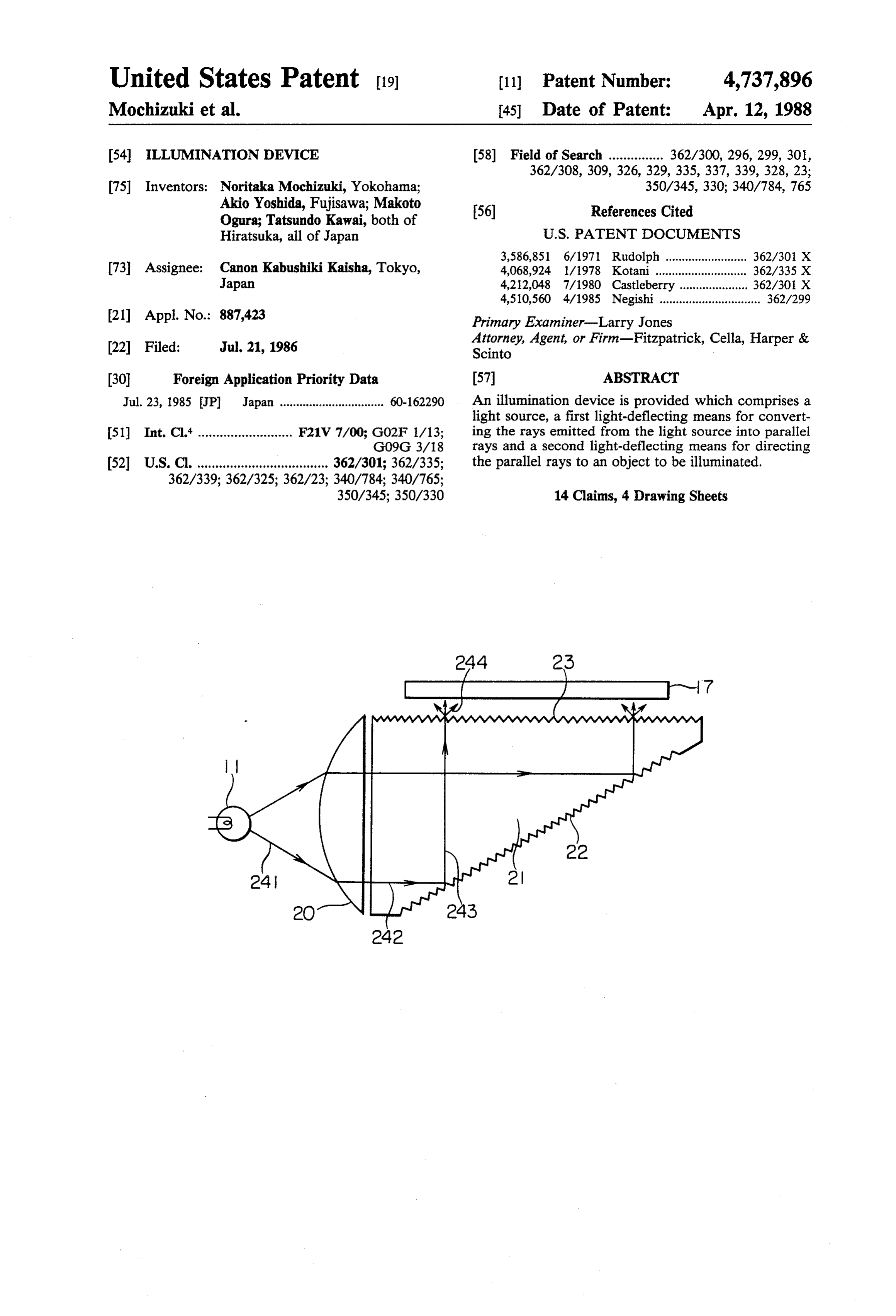
73 Assignee: Canon Kabushiki Kaisha, Tokyo, 4,068,924 1/1978 Kotani ........ ... 362/.335 X Japan 4,212,048 7/1980 Castleberry ..... ... 362/30 X 4,510,560 4/1985 Negishi ............................... 362/299 21 Appl. No.: 887,423 Primary Examiner-Larry Jones Attorney, Agent, or Firm-Fitzpatrick, Cella, Harper & (22 Filed: Jul. 21, 1986 Scinto (30) Foreign Application Priority Data 57 ABSTRACT Jul. 23, 1985 JP Japan ................................ 60-162290 An illumination device is provided which comprises a light source, a first light-deflecting means for convert 51) Int. Cl. .......................... F21V 7/00; G02F 1/13; ing the rays emitted from the light source into parallel G09G 3/18 rays and a second light-deflecting means for directing 52 U.S. C. .................................... 362/301; 362/335; the parallel rays to an object to be illuminated.
350/345; 350/330 14 Claims, 4 Drawing Sheets
Page 2
Drawing sheet — no readable text.
Page 3
Drawing sheet — no readable text.
Page 4
Drawing sheet — no readable text.
Page 5
Drawing sheet — no readable text.
Page 6
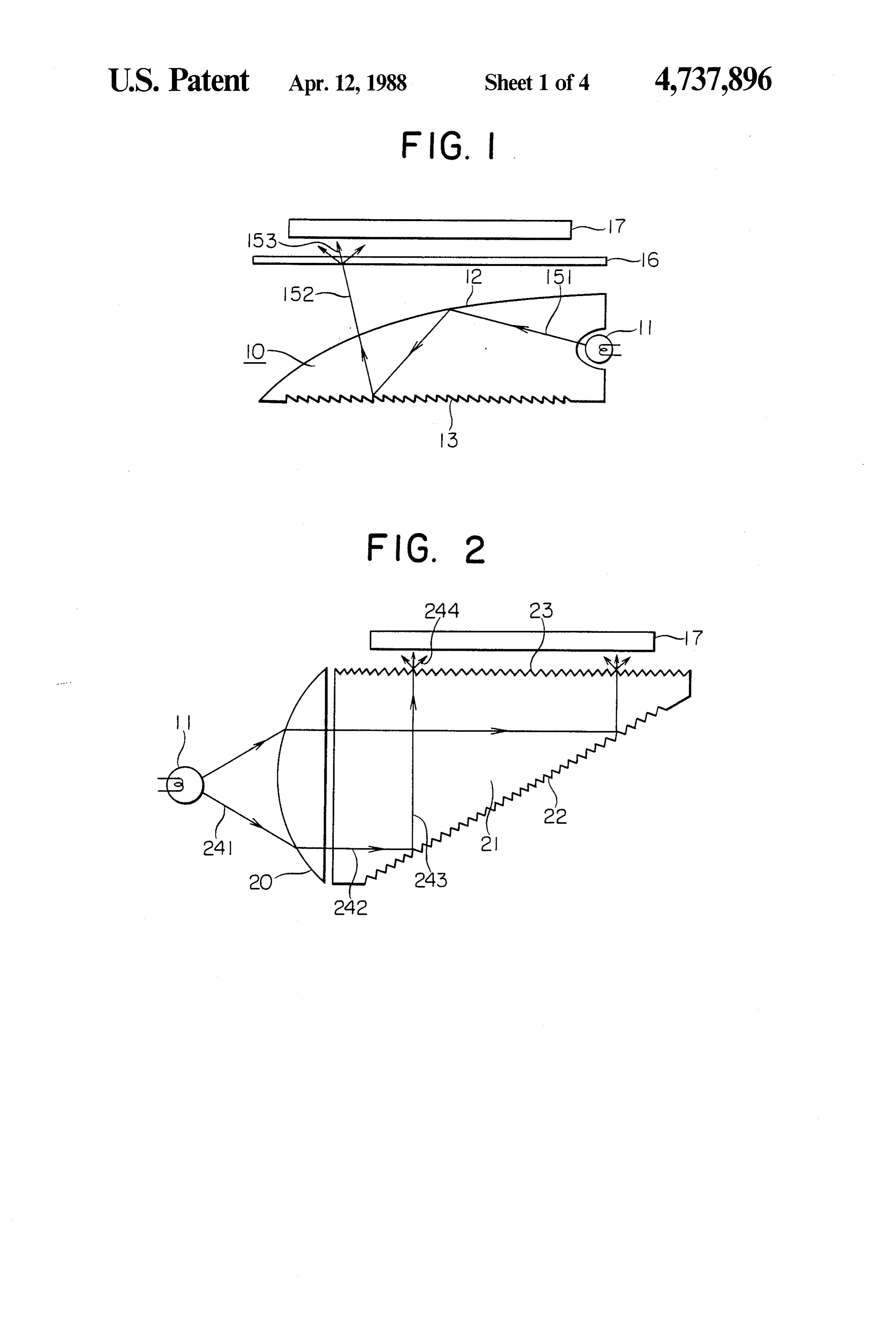
FIG. 2 is a sectional view of an illumination device of
ILLUMINATION DEVICE the present invention.
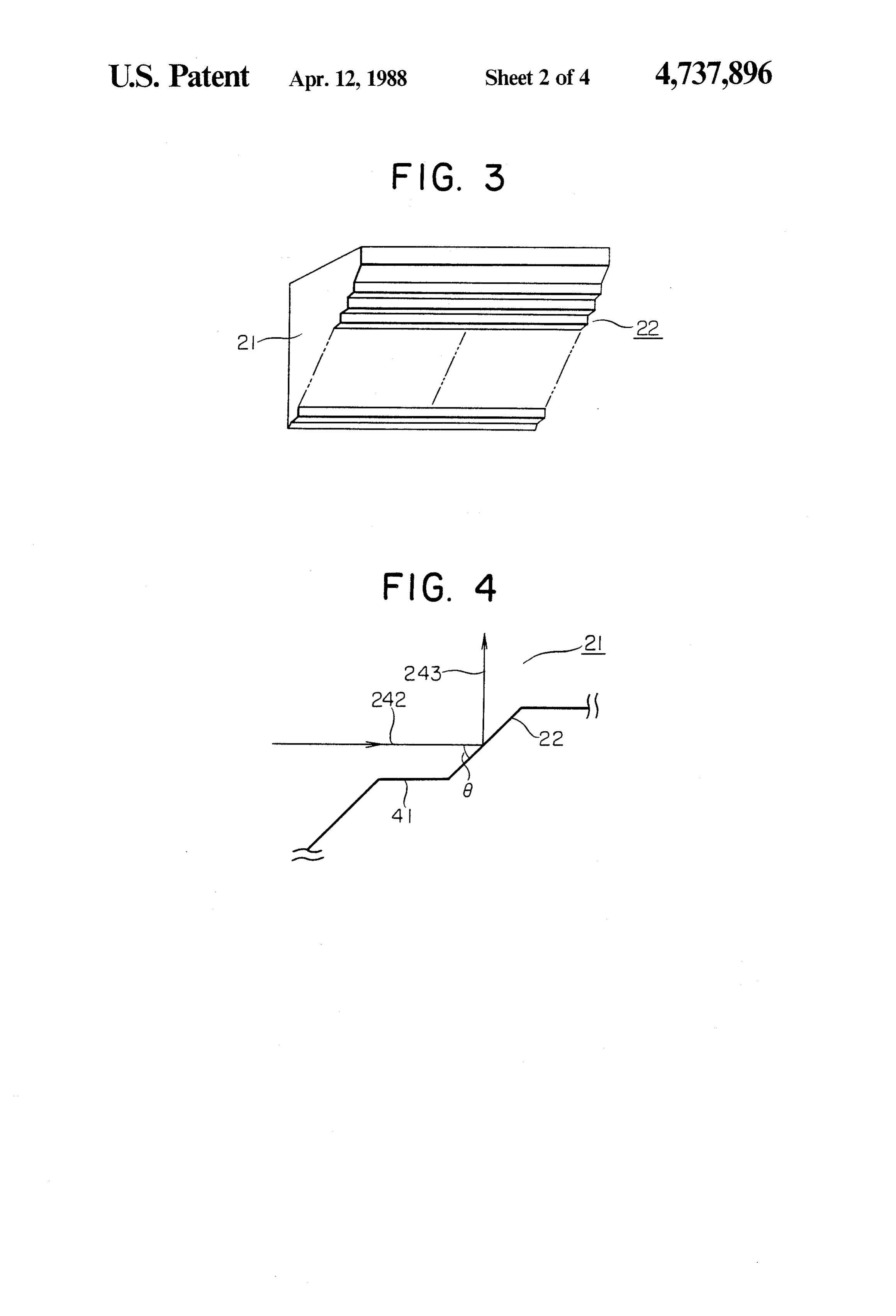
FIG. 3 is a perspective view of a light-guiding mem
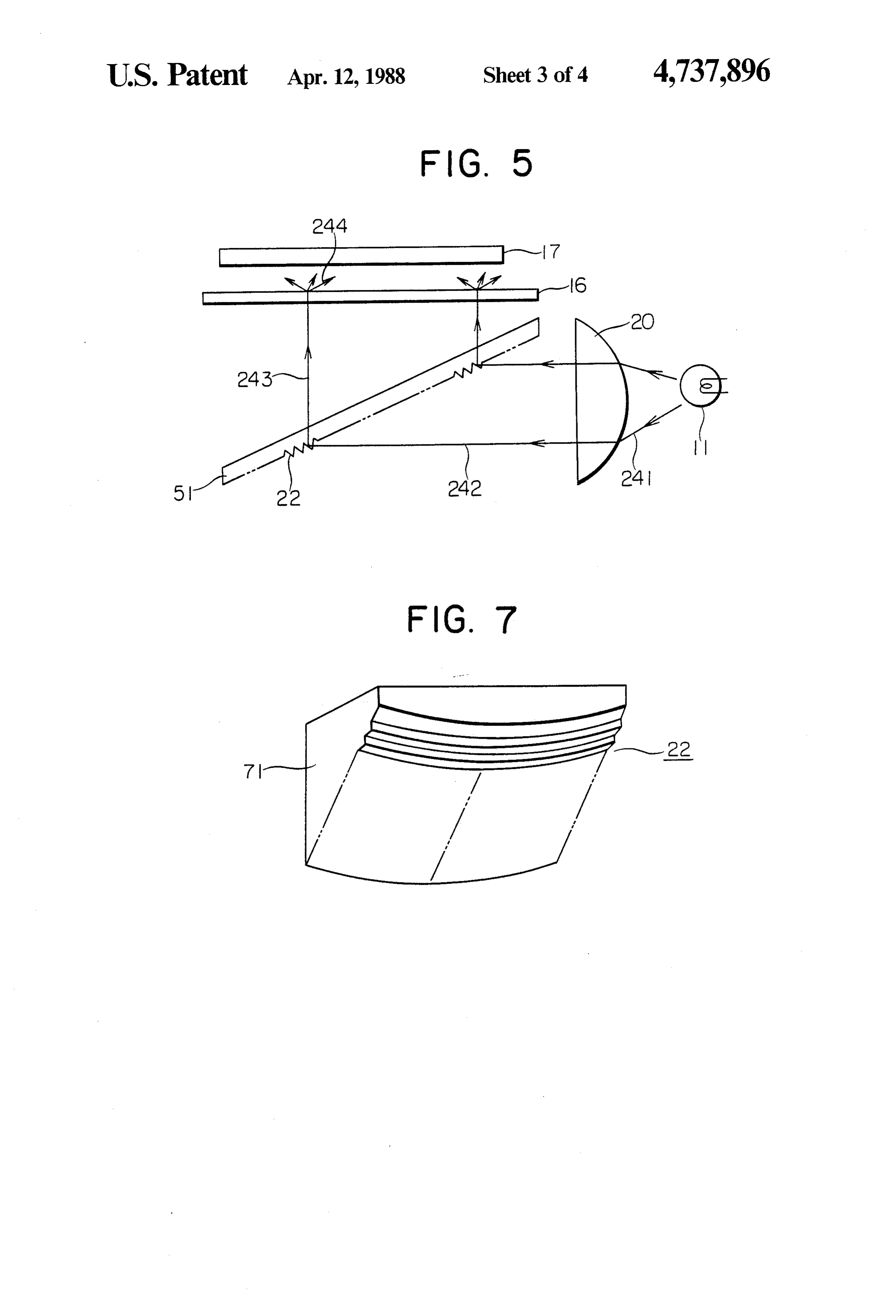
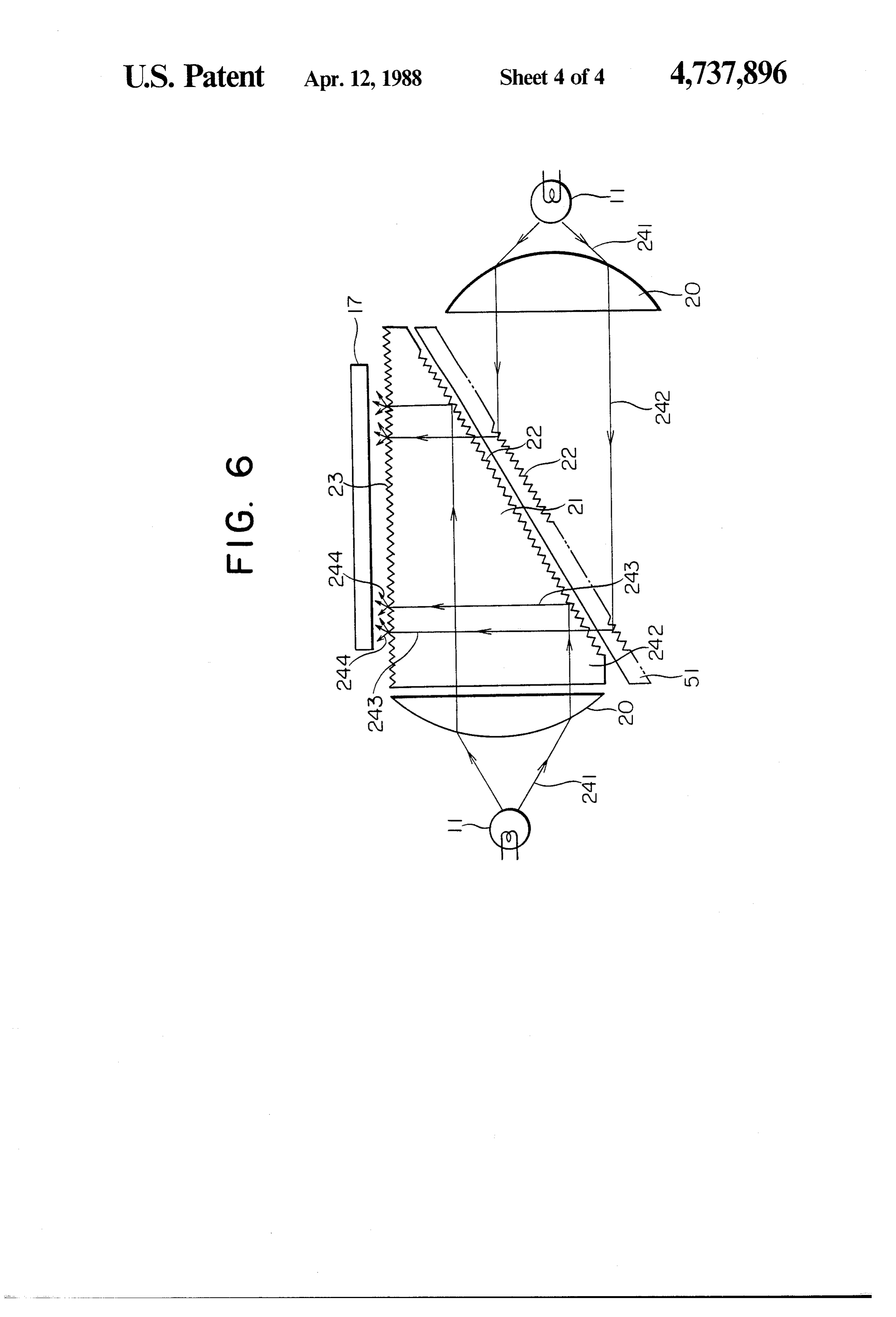
BACKGROUND OF THE INVENTION ber used in the device of the present invention. 1. Field of the Invention FIG. 4 is an enlarged sectional view of an inclined This invention relates to an illumination device. More prism array employed in the present invention. particularly, the present invention relates to a plane FIGS. 5 and 6 are each a sectional view of an illumi illumination device for illuminating display panels of ment. nation device of the present invention in other embodi liquid crystal television, etc. from the back. 10 FIG. 7 is a perspective view of a light-guiding mem 2. Related Background Art ber of other embodiment used in the devices of the In a liquid crystal display panel, display is effected by present invention.
discriminating electrooptical modulation of liquid crys tals by means of reflected light from an irregular reflec DETAILED EXPLANATION OF PREFERRED tion plate placed at the back of the display panel, or 15 EMBODIMENT OF THE INVENTION otherwise by switching the liquid crystal to control FIG. 2 is a sectional view of an illustration device of light introduced from the back of the display panel. In the present invention. FIG. 3 is a perspective view of a general, the former panel is called a reflection-type light-guiding member having planes of an inclined mi liquid crystal and the latter panel is called a transmis nute-prism array, used in the illumination device of sion-type liquid crystal panel. While these two kinds of 20 FIG.
liquid crystal panels have respective advantages, the planes2.ofFIG. the 4 is an enlarged sectional view of the inclined minute-prism array of FIG. 3.
transmission-type liquid crystal panel is particularly The illumination device of the present invention com suitable for use as a display panel for office equipment. prises (a) a first light-deflecting means equipped with a Conventional illumination devices used for transmis sion-type liquid crystal panels employ a plurality of 25 a light source 11 into parallel raysrays convex lens 20 for converting the 241 emitted from 242, and (b) a second fluorescent lamps and a light-diffusing screen. How light-deflecting means equipped with a light-guiding ever, these illumination devices have drawbacks in that member 21 having plane portions 22 of an inclined they consume a large amount of electricity when used for display panels of large area (e.g. diagonal size of 12 prism the array and with a light-scattering plane 23. With illumination device of the present invention, the inches) because of required larger number of fluores 30 rays 241 emitted from the light source 11 placed at the cent lamps for illumination and the resulting non focal point of the convex lens 20 are converted into uniform light for illumination. Therefore, plane illumi parallel rays 242; the parallel rays 242 enter the light nation devices as shown in FIG. 1 are currently in use. guiding member 21 and reflect totally on the minute In FIG. 1, rays 151 emitted from a light source 11 re plane portions 22 of the inclined minute-prism array flect totaly on a curved reflection plane 12 of a transpar 35 whereby the parallel rays 242 are converted into total ent block component 10 and again on the reflection reflection rays 243; the total reflection rays 243 are plane portions 13 of a minute-prism array. The reflected converted into diffused rays 244 on the light-scattering rays 152 are converted into diffused rays 153. The dif plane 23 of the light-guiding member 21; and the dif fused rays 153 can illuminate a liquid crystal panel 17 fused rays 244 illuminate a liquid crystal panel 17 which from the back. is an object to be illuminated. This plane illumination device, however, have the Preferably, each minute prism of the inclined prism following drawbacks. The utilization factor of the rays array used in the present invention has an angle 6 of 45 supplied from the light source is low; a large amount of or smaller with the axis of the parallel rays 242. Also elecrtricity is consumed for illuminating the liquid crys preferably, the inclined prism array, when the object to tal to give a sufficient brightness; and the rays for the 45 be illuminated is a liquid crystal panel, is provided in illumination is inferior in directivity. Accordingly, the such a way that each prism of the prism array has a net light amount for illuminating the portions of the pitch equal to or smaller than the pitch of the picture liquid crystal to be observed becomes inefficient. elements formed on the liquid crystal panel. For in SUMMARY OF THE INVENTION stance, when the liquid crystal panel comprises 16 pic 50 ture elements per 1 mm, the inclined prism array is
An object of the present invention is to provide a desirably provided so as to have 16 or more prisms per plane illumination device wherein the rays supplied 1 mm, and further the plane portions 22 of the inclined from a light source is utilized at a high degree and prism array having an angle 6 to the parallel rays 242 is which provides rays of superior directivity for illumina desired to oppose the picture elements of the liquid tion. 55 crystal panel. In this case, therefore, the amount of the Another object of the present invention is to provide rays which can transmit through the picture elements a plane illumination device suitable for use as a back becomes maximum when the picture elements are in light for transmission-type liquid crystal panels. open state. Meanwhile, the plane portions 41 of the According to the present invention, there is provided prism array parallel to the parallel rays 242 oppose the an illumination device comprising a light source, a first 60 portions of the liquid crystal panel portions other than light-deflecting means for converting the rays emitted the picture elements and accordingly these portions of from the light source into parallel rays and a second the liquid crystal are illuminated by the minimum light-deflecting means for directing the parallel rays to amount of rays, thus providing a picture of high con an object to be illuminated. trast on the display panel.
BRIEF EXPLANATION OF THE DRAWINGS
65 On the picture formed on liquid crystal panel 17, a plurality of picture elements are arranged in lines and
FIG. 1 is a sectional view of a conventional illumina rows. Each picture element is controlled to be either in tion device. a open state or in a closed state. A picture is displayed
Page 7
by switching the ray of the back light through the con light device for transmission-type liquid crystal panels, trolled picture element. The control of the picture ele a display two times brighter or more than the conven ments is effected generally in accordance with the infor tional display can be provided.
mation signal from the scanning line and the data line What we claim is:
wired to the picture elements. For the liquid crystal 5 1. An illumination device comprising: panel 17, an active matrix system of displaying images, a. a light source;
a twisted nematic system for a dot-matrix picture, or a b. a display panel having picture elements arranged in system for a dot-matrix picture employing ferroelectric rows and columns, each of the picture elements liquid crystals may be used. In the active matrix system, being independently controlled to be either in an each picture element on the same line is commonly 10 open state or in a closed state; wired to the gates of a thin film transistors (TFT's), and c. A first light-deflecting means for converting the the picture elements in the same line are commonly rays emitted from the light source into parallel wired to the gates of TFT's and the information signal rays; and is applied sequentially to each line from the source of the TFT's in synchronization with the gate-on-pulse. 15 d. plane a second light-deflecting means having a reflection for directing the parallel rays to the display
The light-guiding member 21 employed in the illumi panel, the reflection plane being formed by a prism nation device of the present invention may be a trans array, and the pitch between the prisms in the parent material made from glass, a synthetic resin or the prism array being smaller than the pitch between like. However, it may be a colored transparent compo the image elements in the display panel. nent depending upon the application purpose of the 20 2. An illumination device present device. The light-scattering plane 23 of the wherein the first light-deflectingaccording to claim 1, light-guiding member 21 can be a rough plane formed and the light source is placed at the focal point oflens, means is a convex the by a non-glare treatment. convex lens.
The plane portions 22 of the inclined prism array can 3. An illumination device according to claim 1, be covered by a reflective metal film of aluminum, 25 wherein prism faces of the prism array inclined in the silver, chromium or the like to increase the utilization factor of the rays supplied from the light source 11. parallel rays are inclined at the angle of 45 or less rela The light source 11 used in the present apparatus can tive to the optical axis of the parallel rays. be selected from various light sources. Specific exam 4. An illumination device according to claim 1, ples include a long fluorescent lamp, a long incandes 30 wherein the second light-deflecting means comprises a cent electric lamp (e.g. a halogen lamp), a long LED light scattering plane for converting the parallel rays (light-emitting diode), etc. reflected by the reflection plane into scattered light. FIGS. 5 to 7 show other embodiments of the illumi 5. An illumination device according to claim 1, nation device of the present invention. wherein the reflection plane is curved. The illumination device shown in FIG. 5 comprises a 35 6. An illumination device according to claim 1, wherein the second light-deflecting means is made of first light-deflecting means using a convex lens 20 for glass.
converting the rays 241 emitted from a light source 11 to parallel rays, and a second light-deflecting means 7. An illumination device according to claim 1, using a transparent plate 51 having plane portions 22 of wherein the reflection plane is formed of a prism array, an inclined prism array. In FIG. 5, the same numerical 40 and the prism array is coated by reflective metal film. symbols as in FIG. 2 represent the same member as in 8. An illumination device according to claim 1, FIG. 2, respectively. wherein the display panel comprises ferroelectric liquid FIG. 6 shows an embodiment of a composite type of crystal.
illumination device which is virtually a combination of 9. An illumination device according to claim 1, the devices of FIG. 2 and FIG. 5. In FIG. 6, the same 45 wherein the display panel comprises twisted nematic numerical symbols as in FIGS. 2 and 5 represent the liquid crystal.
same members as in FIGS. 2 and 5, respectively. 10. An illumination device comprising: In the illumination device of FIG. 6, light sources 11 a. a first light source and a second light source; are arranged at the both sides of the light-deflecting b. a display panel having picture elements arranged in means, thus enabling intense illumination. Further, the 50 rows and columns, each of the picture elements rays of good directivity can illuminate a liquid crystal being independently controlled to be either in an panel uniformly from the back. open state or in a closed state; FIG. 7 is a perspective view of a light-guiding mem c. a first light-deflecting means for converting the ber 71 wherein the plane portions 22 of the inclined light emitted from the first light source into a first prism array are curved. In the illumination device of the 55 set of parallel rays, and a second light-deflecting present invention, this light-guiding member 71 can be means for converting the light emitted from the used in place of the light-guiding member 21 of FIG. 2. second light source into a second set of parallel With the light-guiding member 71 having the curved rays;
plane portions 22, the parallel rays which have entered d. a third light-deflecting means having a first reflec the light-guiding member 71 reflect on the curved plane tion plane for directing the first set of parallel rays portions 22 so that the reflected rays are directed to the display panel, the first reflection plane being toward the center of the prism array, whereby the rays formed by a prism array; and illuminating a liquid crystal panel can have an improved e. a fourth light-deflecting means having a second directivity property. reflection plane for directing the second set of With the use of the illumination device of the present 65 parallel rays to the display panel, the second reflec invention, the utilization of the rays from a light source tion plane being formed by a second prism array, becomes higher and rays of superior directivity can be and the second reflection plane being placed in a obtained. When the present device is applied as a back position in which the reflected rays from the sec
Page 8
ond reflection plane illuminates the display panel array inclined to the second set of parallel rays are through the third light deflecting means. inclined at the angle of 45 or less relative to the optical 11. An illumination device according to claim 10, axis of the second set of parallel rays. wherein the first and second light deflecting means are 13. An illumination device according to claim 10, respectively a first and a second convex lenses, and the 5 wherein the third light-deflecting means comprises a first and the second light sources are placed respec light scattering plane for converting the rays reflected tively at the focal points of the first and the second by the first and the second reflection planes into scat convex lenses. tered light.
12. An illumination device according to claim 10, 14. An illumination device according to claim 10, wherein the prisms faces of the first prism array inclined O wherein the pitch between the prism in the first prism to the first set of parallel rays are inclined at the angle of array is smaller than the pitch in the image elements of 45 or less relative to the optical axis of the first set of the display panel. is is a parallel rays, and the prism faces of the second prism

Page 9
UNITED STATES PATENT AND TRADEMARK OFFICE
CERTIFICATE OF CORRECTION
DATED April 12, 1988 Page 1 of 2 INVENTOR(S) : Noritaka MOCHIZUKI ET AL.
It is Certified that error appears in the above-identified patent and that said Letters Patent is hereby Corrected as shown below:
COLUMN 1
Line 34, "totaly" should read -- totally--; line 37, "152 are" should read --152 leave the curved reflection plane 12 to transmit through a light-diffusing screen. 16, whereby the reflected rays 152 are--; and line 40 "have" should read -- has -- .
COLUMN 2
Line 16, "illustration" should read -- illumination--; line 68, "a open" should read -- an open--.
COLUMN 3
Line ll, "a" should be deleted.
COLUMN 4
Line 2, "brighter or more' should read -- or more
COLUMN 5
Line 1 "illuminates" should read--illuminate--;
Page 10
UNITED STATES PATENT AND TRADEMARK OFFICE
CERTIFICATE OF CORRECTION
DATED : April 12, 1988 Page 2 of 2 INVENTOR(S): iNoritaka Mochizuki et all
It is certified that error appears in the above-identified patent and that said Letters Patent is hereby corrected as shown below:
COLUMN 5, line 10, "prisms' should read --prism--.
Signed and Sealed this
Twenty-fifth Day of October, 1988
Attest.
DONALD J. QUIGG
Attesting Officer Commissioner of Patents and Traclemarks
Provenance
- Collection
- Cited prior art
- Original PDF
- patentimages.storage.googleapis.com →
- Filed
- 1986-07-21
- Pages
- 10
- Method
- pdftotext (the PDF's own text layer) + pdftoppm 300dpi page scans
- Source
- Google Patents bibliographic record
- Granted
- 1988-04-12
- Inventors
- Noritaka Mochizuki; Akio Yoshida; Makoto Ogura; Tatsundo Kawai; Canon Inc
- Transcribed from
- patentimages.storage.googleapis.com →