patent · US5205994
Electrolytic ozone generator
27 April 1993
Page 1 — bibliographic record
United States Patent (19) 11 Patent Number: 5,205,994 Sawamoto et al. 45) Date of Patent: Apr. 27, 1993 54 ELECTROLYTICOZONE GENERATOR Primary Examiner-Donald P. Walsh Assistant Examiner-Daniel J. Jenkins 75 Inventors: Isao Sawamoto, Kanagawa; Takayuki Attorney, Agent, or Firm-Sughrue, Mion, Zinn, Shimamune, Tokyo, both of Japan Macpeak & Seas 73) Assignee: Permelec Electrode, Ltd., Kanagawa, 57 ABSTRACT Japan 21 Appl. No.: 755,424 An electrolytic ozone generator is described, which comprises a feed tank in which water is stored, an ion 22 Filed: Sep. 4, 1991 exchange column connected to the feed tank, a pump (30) Foreign Application Priority Data for feeding the stored water in the feed tank to the ion-exchange column, an electrolytic cell connected to
Sep. 6, 1990 JP Japan .................................. 2-236210 the ion-exchange column and containing a solid electro 51) Int. Cli.............................................. B01J 19/08 lyte which is an ion-exchange membrane, an anode 52 U.S. Cl. ................. ... 422/186.07; 204/128 disposed tightly on one side of the solid electrolyte, and 58 Field of Search ........................... 422/186, 186.07; a cathode disposed tightly on the other side of the solid 204/128, 129, 149, 152, 295, 296,294 electrolyte, an electromagnetic valve connected to and (56) References Cited disposed between the ion-exchange column and the electrolytic cell, and a hydrogen-separating column
l,581,944 4/1926 Hausmeister ........................ 204/149 hydrogen from a gas-liquid mixture sent from the elec 3,623,970 11/1971 Haas.................................... 2O4/314 trolytic cell and circulating the resulting water to the 3,900,377 8/975 Enns et al. .......................... 204/149 feed tank, and in which the liquid level of the anolyte in 4,190,515 2/1980 Butler et al. ........................ 204/266 the electrolytic cell is sensed, and, in a case wherein said 4,311,569 1/1982 Dempsey et al. . . 204/129 liquid level is below a predetermined value, ion 4,470,891 9/1984 Moore et al. ...... 204/98 exchanged water is fed from the ion-exchange column 4,596,648 6/1986 Sweeney ... 204/237 to the electrolytic cell by controlling the electromag 4,761,208 8/1988 Gran et al. . 204/95 4,804,449 2/1989 Sweeney ........ 204/2S6 netic valve.
4,978,438 12/1990 Shimamuneet al. ............... 204/265 2 Clains, 1 Drawing Sheet
Page 2
Drawing sheet — no readable text.
Page 3
electrolysis but also when part of the anolyte penetrates
ELECTROLYTIC OZONE GENERATOR as migrant water through the ion-exchange membrane from the anode side to the cathode side together with
FIELD OF THE INVENTION positive ions. In the case of ordinary perfluorocarbon The present invention relates to an ozone generator 5 ber sulfonic acid-based ion-exchange membranes, the num which produces ozone through water electrolysis. positive of such migrant water molecules is from 2 to 2.5 per More particularly, the invention relates to an ozone cantly large ion, such a migrant water amount being signifi generator for producing ozone gas or ozone-containing because it is four- to five-fold larger than water for use in the treatment of swimming-pool water, O the amount of water which undergoes electrolysis. Be wafer treatment in semiconductor production pro to cause of the above, a large quantity of pure water is fed cesses, or chemical reactions. the electrolytic cell normally by using a relatively large-sized ion-exchange column. However, this con
BACKGROUND OF THE INVENTION ventional method involves problems in terms of cost Ozone as a powerful and clean oxidizing agent has 15 and equipment construction, because the migrant piire been attracting increased attention. The use of ozone water is discarded and because of the necessity of use of particularly for water treatment has been increasing a large-sized ion-exchange column and of replacement since treatment with ozone is advantageous, for exam of the ion-exchange resin with fresh one at short inter ple, in that because the product of ozone decomposition vals. These problems constitute obstacles particularly to is oxygen, ozone-treated water is not caused to contain 20 easy maintenance of the apparatus. any residual substance, unlike conventional chlorine SUMMARY OF THE INVENTION treated water, and in that the decomposition rate of ozone is so high that ozone itself does not remain in the An object of the present invention is to provide an treated water; hence, there are no problems of second electrolytic ozone generator which, when used for ary pollution. For producing ozone which is a useful ozone generation using high-purity water, enables the oxidizing agent as described above, electrical discharge 25 ion-exchange operation for producing pure water to be methods and electrolytic methods have mainly been conducted at a minimal load without lowering ozone employed conventionally. At present, however, the generating efficiency, by effectively using the high electrolytic methods are most typically employed, be purity water to maintain the anolyte level at a predeter cause of the advantages of product purity and ease of 30 mined value or a higher value.
operations. The electrolytic ozone generator of the present in The above advantages are brought about because the vention comprises a feed tank in which water is stored, electrolytic ozone generators (electrolytic ozonizers) an ion-exchange column connected to the feed tank, a used in the electrolytic methods employ as the anode a pump for feeding the stored water in the feed tank to the lead oxide-based electrode performing an excellent ion-exchange column, an electrolytic cell connected to ozone-evolving function. Due to such ozonizers, ozone 35 ion-exchange column and containing a solid electro can be obtained at high concentrations by conducting the lyte which is an ion-exchange membrane, an anode procedures almost the same as those in ordinary water disposed tightly on one side of the solid electrolyte, and electrolysis. In such ozone generators, pure water (ion exchanged water) is used as the raw material and a aelectrolyte, cathode disposed tightly on the other side of the solid an electromagnetic valve connected to and perfluorocarbon sulfonic acid-based ion-exchange disposed between the ion-exchange column and the membrane is mainly used as a solid electrolyte, in com electrolytic cell, and a hydrogen-separating column bination with lead dioxide as the anode, to generate connected to the electrolytic cell and for separating ozone. By this method, oxygen containing ozone gas at hydrogen from a gas-liquid mixture sent from the elec a concentration of about 15% can be obtained. The thus-produced ozone-containing oxygen may be used as 45 trolytic cell and circulating the resulting water to the it is or after being dissolved in water to give ozone-con feed tank, and in which the liquid level of the anolyte in taining water. This electrolytic method is advantageous the electrolytic cell is sensed, and, in the case where the liquid level is below a predetermined value, ion in that the apparatus has a simple structure and its oper exchanged water is fed from the ion-exchange column ation is simple. Hence, attention is now focused on this to the electrolytic cell by controlling the electromag apparatus, among small-sized ozonizers producing small 50 netic valve. In another amounts of ozone, which is regarded as an ozone gener where the liquid level aspect of this apparatus, in a case is not below the predetermined ator that generates ozone at a high concentration.
However, this ozone generator with excellent perfor value, ion-exchanged water from which impurities have mance has some drawbacks. The most serious of these is been removed in the ion-exchange column may be cir that high-purity pure water (or ion-exchanged water) 55 culated to the feed tank by controlling the electromag should be fed to the ozone generator in order to protect netic valve.
its ion-exchange membrane; the pure water should be BRIEF DESCRIPTION OF THE DRAWING regulated so as to have an electrical conductivity of 1
LS/cm or less if possible, and 10 S/cm or less at the view ofdrawing
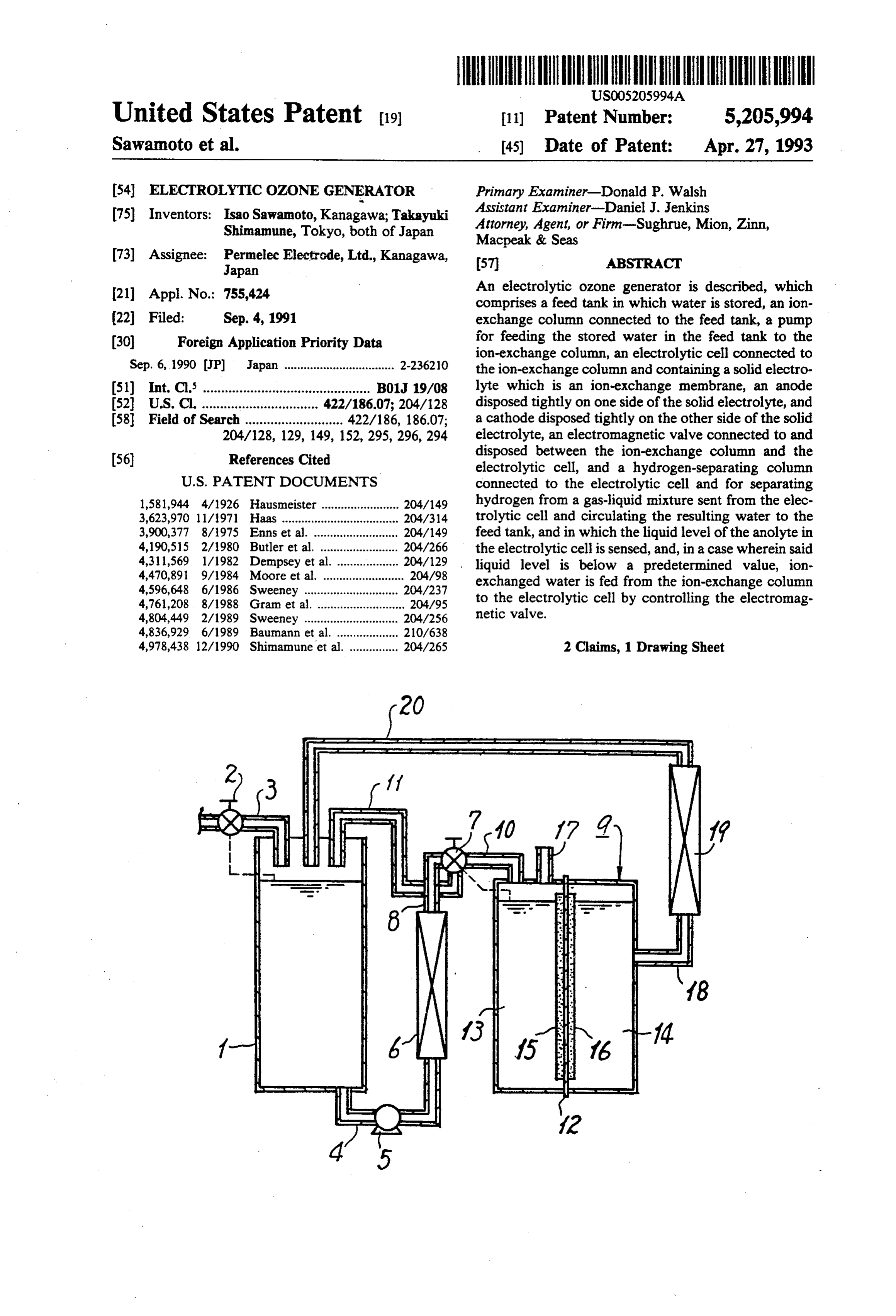
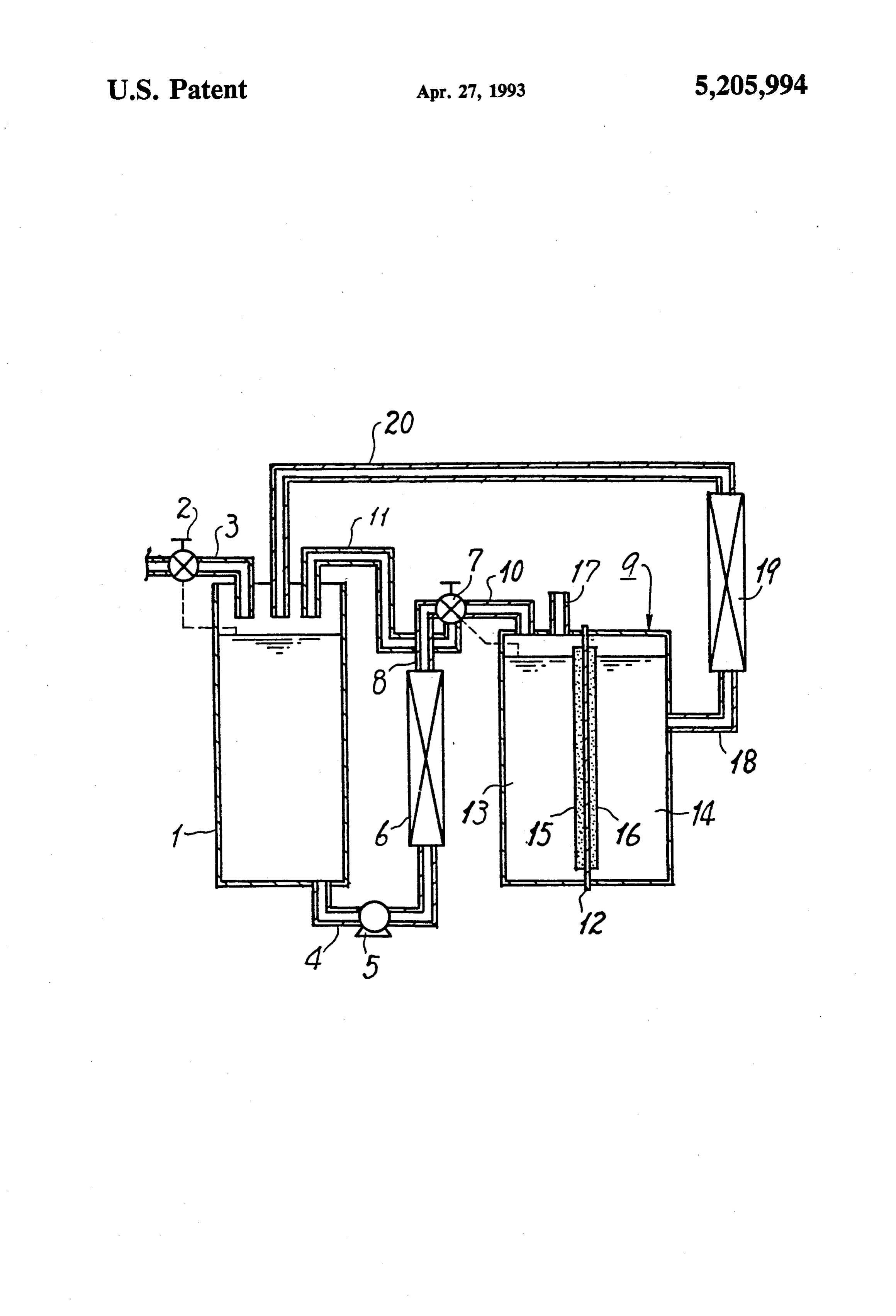
The one is a diagrammatic vertical sectional example of the electrolytic ozone generator worst. For maintaining such an electrical conductivity, the ozone generator is equipped with an ion-exchange according to the present invention.
column packed with an ion-exchange resin before the DETAILED DESCRIPTION OF THE electrolytic cell, and the feed water is allowed to pass INVENTION through the ion-exchange column, where impurities are removed from the water, and the resulting water is then vention is characterized in generator 65 The electrolytic ozone that in of the present in order to minimize the fed to the electrolytic cell.
The anolyte in the electrolytic cell, however, de amount of ion-exchanged water (pure water) used in the creases in amount not only by consumption through apparatus, the water which has undergone electrolysis
Page 4
and is taken out of the electrolytic cell is circulated to this ion-exchange column operates under a light load the feed tank and then fed again to the electrolytic cell. because it serves only to perform ion exchange of the The electrolytic cell employed in the ozone generator water to be subjected to electrolysis, a small-sized col of the present invention has a structure of the so-called umn packed with a relatively small amount of anion-ex solid polymer electrolyte (spe) type in which an ion-ex change resin is sufficient as the ion-exchange column. It change membrane, preferably a perfluorocarbon sul is desirable that the kind of the ion-exchange resin fonic acid-based one, is used as a solid electrolyte and packed in the column be selected according to the kind this ion-exchange membrane is covered on both sides of impurities contained in the water fed to the feed tank. with an anode and a cathode. It is preferred that the Upon application of electricity to the electrolytic cell ion-exchange membrane be a cation-permeable mem 10 and feeding of ion-exchanged water deionized in the brane. Use of a cation-permeable ion-exchange mem ion-exchange column to the anode chamber of the elec brane is advantageous in that cation accumulation in the trolytic cell, the ion-exchanged water is electrolyzed to electrolytic cell and circulating system can be avoided generate a gaseous mixture of ozone and oxygen. This because cations (e.g., metal ions) that have come into gaseous mixture can be removed from the cell through the anode chamber penetrate through the ion-exchange 15 an ozone-containing gas withdrawal opening provided membrane to enter the cathode chamber, subsequently at the top of the anode chamber. Alternatively, the pass through the hydrogen-separating column and the ozone generated may be removed from the cell in the feed tank, and then enter the ion-exchange column, form of ozone-containing water in which the ozone where the cations are removed. containing gas has been dissolved, from an ozone-con The material for the anode chamber in the electro 20 taining water withdrawal opening provided at a proper lytic cell is not particularly limited, as long as it pos position of the anode chamber. Further, part of the sesses ozone resistance. For example, titanium, Teflon ion-exchanged water (electrolyte) in the anode chamber (trademark), or the like can be used. As the material for penetrates as migrant water through the ion-exchange the cathode chamber, titanium, stainless steel, Teflon, membrane along with cations dissolved in the water, as poly(vinyl chloride), polypropylene, or the like can be 25 described hereinabove. That is, the migrant water used. moves, in an amount of 2 to 2.5 water molecules per The anode material and cathode material covering cation, through the ion-exchange membrane into the both sides of the above-described ion-exchange mem cathode chamber, where it is electrolyzed to evolve brane are not particularly limited. For example, the hydrogen gas, and the resulting electrolyte is removed anode material can be 3-lead dioxide or the like and the 30 from the cell together with the evolved hydrogen gas. cathode material can be a platinum group metal or an Accordingly, as the electrolysis proceeds, the amount oxide thereof. In the case where 3-lead dioxide is to be of the electrolyte in the anode chamber decreases and used as the anode material, it is desirable that a titanium hence its liquid level lowers. In the present invention, substrate having micro pores be first covered with a an electromagnetic valve is provided between the ion prime coat of, for example, platinum, gold, etc., and a 35 exchange column and the electrolytic cell. This electro layer of 6-lead dioxide then be formed thereon by elec magnetic valve serves not only to prevent the back flow trodeposition. In the case where platinum, ruthenium of evolved gases or the electrolyte from the electrolytic oxide, or the like is to be used as the cathode material, cell to thereby pressurize the anode chamber, but also to it is desirable that a substrate made of titanium, stainless regulate the liquid level of the anolyte. That is, the steel, or carbon and having micro pores be coated with 40 electrolyte level in the anode chamber is sensed by a a paste prepared by kneading a powder of platinum or suitable sensor, and in the case where the electrolyte other desired cathode material with a binder, and the level has decreased below a predetermined value, the coated substrate is then subjected to hot-press shaping. electromagnetic valve is controlled so that the ion In place of covering substrates with electrode materials exchanged water in the ion-exchange column is fed as as described above, an electrolytic cell may be con 45 an electrolyte to the anode chamber in the electrolytic structed by a method in which each electrode material cell, to thereby maintain the electrolyte level in the is prepared separately from the ion-exchange mem anode chamber at or above the predetermined value. In brane, the electrode materials and the ion-exchange the case where the above electrolyte level sensed by the membrane are superposed in the order of anode materi sensor is not below the predetermined value, the pump al/ion-exchange membrane/cathode material, and the is stopped to thereby suspend feeding of the water in the superposed structure is bolted together after being sand feed tank to the ion-exchange column, or the electro wiched between feeder materials. magnetic valve is controlled so that the ion-exchanged Preferred electrolysis conditions include a current water in the ion-exchange column is circulated to the density of about 50-150 A/dm2, cell voltage of about feed tank. By this circulation, the purity of the ion 3.0-3.5 V, and liquid temperature of about 25-35 C. It 55 exchanged water to be fed to the electrolytic cell is should be noted that there are cases where according to further improved.
the current quantity, the temperature rises too high due Hydrogen gas evolved in the cathode chamber by to heat generated by the electrolysis. It is preferable in electrolysis is removed from the cell along with the such a case to lower the temperature by means of cool electrolyte in the cathode chamber, and then separated ing water. from the electrolyte in the hydrogen-separating col The feed water to be fed to the electrolytic cell is umn. Thereafter, at least part of the resulting water is deionized beforehand in order to protect the ion-ex circulated to the feed tank, subjected again to ion ex change membrane. For this purpose, a feed tank for change, and then used in electrolysis. The reason why storing tap water or other kind of water and an ion-ex the water from which hydrogen has been separated is change column and other necessary devices for deioniz 65 not directly fed to the anode chamber is that there are ing the water in the fed tank are provided before the cases where this water contains impurities that have electrolytic cell, and the water in the feed tank is fed to dissolved thereinto in the anode and cathode chambers, the ion-exchange column by means of a pump. Since although the amount of such impurities is slight.
Page 5
The water-sending from the cathode chamber ity is applied to the electrolytic cell, with the anode through the hydrogen-separating column to the feed chamber 13 and the cathode chamber 14 being filled tank can be conducted without using a pump or similar with an electrolyte (e.g., water). Upon the application means if the hydrogen-separating column is designed or of electricity, an ozone-containing gas is generated in disposed so that its uppermost part is at the highest the anode chamber and is removed from the cell level, because the pressure in the cathode chamber through the withdrawal opening 17. Further, part of sends the catholyte to the hydrogen-separating column, that anolyte in the anode chamber which contains hy and the water then flows naturally from the hydrogen drated cations penetrates through the solid electrolyte separating column into the feed tank due to the differ 12 to enter the cathode chamber 14. Therefore, the ence in elevation. w 10 amount of the electrolyte in the anode chamber 13 de The water level in the feed tank also fluctuates, and it creases because a part of the electrolyte is consumed by may be controlled by sensing the water level by a sensor the electrolysis and another part migrates through the or other means and supplying the feed tank with city solid electrolyte 12 to the cathode chamber 14. Thus, water, ion-exchanged water, or other kind of water in the water level in the anode chamber lowers. an amount determined based on the sensed water level. 15 On the other hand, the water stored in the feed tank In the ozone generation using the apparatus of the 1 is led to the ion-exchange column 6 by means of the present invention, water supply for the ozone genera pump 5 and converted to ion-exchanged water in the tion can be conducted only in an amount substantially ion-exchange column 6. In the case wherein the anolyte equal to the amount of water consumed by the electrol ysis, and the ion-exchange column can be operated 20 level mined in the electrolytic cell 9 is not below a predeter value, the ion-exchanged water removed from under a far lower load than those in conventional ozone the ion-exchange column 6 is returned to the feed tank generators because high-purity water is always fed to 1 by controlling the the ion-exchange column which performs ion exchange. netic valve. In the cock case direction for the electromag wherein the anolyte level is
One example of the ozone generator according to the found to have been lowered to a value below a prede present invention is explained below with reference to termined value by means of a suitable sensor,
the ion the accompanying drawing. exchanged water is fed to the anode chamber 13 in the To a box-shaped feed tank 1 there is connected a raw electrolytic cell 9 by controlling the electromagnetic water feed pipe 3 provided with a valve 2 for feeding valve. Due to this operation, the anolyte level in the city water, well water, or other water. The water level in the feed tank 1 is sensed by known mechanical or 30 anodemined chamber 13 is always kept at or above a predeter value. As a result, the anode material is in suffi electrical liquid level sensing means such as a flat sen cient contact with the anolyte and ozone generation is sor, an electrostatic capacitance sensor, etc., and in a conducted efficiently.
case wherein the water level has gone below a predeter The catholyte is also consumed by the electrolysis. mined value, raw water is supplied to the feed tank 1 by However, the catholyte level increases as the electroly opening valve 2. To the bottom of the feed pipe 4. The sis proceeds,
other end of the stored water feed pipe 4, in which a from the anodebecause the amount of the migrant water pump 5 has been disposed, is connected to the bottom of lyte consumedchamber is larger than that of the catho by the electrolysis. The increased an ion-exchange column 6packed with an ion-exchange amount of the catholyte is led through the withdrawal resin. To the top of the ion-exchange column 6 is con opening 18 to the hydrogen-separating column 19, nected an ion-exchanged water feed pipe 8 provided at its end with an electromagnetic valve 7 which is a three where hydrogen is separated. At least part of the result way cock. Through the electromagnetic valve 7, this ing water is circulated through the circulation pipe 20 feed pipe 8 is connected to an electrolyte feed pipe 10 back to the feed tank 1, stored in the feed tank 1, subse for feeding ion-exchanged water to an electrolytic cell quently subjected to ion exchange in the same manner 9, and is also connected to an ion-exchanged water 45 as As described above, and then reused in the electrolysis. described above, the ozone generator according circulation pipe 11 for circulating ion-exchanged water to the feed tank 1. to the present invention is advantageous in that the The electrolytic cell 9 is partitioned into an anode amounts of the required ion-exchange resin and feed chamber 13 and a cathode chamber 14 by means of a water can be greatly reduced, and the ion-exchange solid electrolyte 12 constituted by an ion-exchange 50 column can hence be reduced in size, because the gas membrane of the perfluorocarbon sulfonic acid type or liquid mixture containing hydrogen removed from the other type. The solid electrolyte 12 is covered on its cathode chamber is subjected to hydrogen separation anode chamber 13 side with an anode material 15 and on and then circulated to the feed tank in which water to its cathode chamber 14 side with a cathode material 16. be supplied to the anode chamber is stored. In addition, Numeral 17 denotes a withdrawal opening for an ozone 55 since the anolyte level is sensed so that feeding of ion containing gas evolved in the anode chamber 13. exchanged water to the electrolytic cell can be con To the side wall of the cathode chamber 14 in the ducted exactly in the necessary minimum quantity, the electrolytic cell 9 is connected the base end part of a ion-exchanged water can be used in electrolysis without withdrawal pipe 18 for a gas-liquid mixture of hydrogen wasting it, and the electrolysis results in almost no gas evolved in the cathode chamber and the catholyte. 50 wastewater.
The other end of the withdrawal pipe 18 is connected to Moreover, in the case wherein there is no need for a hydrogen-separating column 19. To the other side of ion-exchanged water to be fed from the ion-exchange the hydrogen-separating column 19 is connected a cir column to the electrolytic cell, the ion-exchanged water culation pipe 20 for circulating the water from which can be circulated to the feed tank and subjected again to hydrogen has been separated in the hydrogen-separat 65 ion exchange. By this ion-exchanged water circulation, ing column 19 back to the feed tank 1. the purity of the ion-exchanged water fed to the electro In practicing ozone generation using the ozone gener lytic cell can be improved further, without substantially ator having the above-described construction, electric increasing the load placed on the ion-exchange column.
Page 6
The present invention is explained in more detail by use of the ozone generator of this example, the amount reference to the following example in which ozone of supplied water can be reduced to a value only frac generation is conducted using an ozone generator ac tionally as large as the conventional supplied water cording to the present invention. However, the example amount (at the amount of water passing through the is not to be construed as limiting the scope of the inven 5 electrolytic cell).
tion. While the invention has been described in detail and EXAMPLE with reference to specific embodiments thereof, it will be apparent to one skilled in the art that various changes
According to the accompanying drawing, an ozone and modifications can be made therein without depart generator was constructed as follows. 10 ing from the spirit and scope thereof, Using NAFION (a perfluorosulfonic acid membrane What is claimed is:
which is a trademark product of du Pont) 117 having a 1. An electrolytic ozone generator which comprises a length of 10 cm and a width of 10 cm as a solid electro feed tank in which water is stored, an ion-exchange lyte, an electrolytic cell having an electrode area of 1 column connected to the feed tank, a pump for feeding dm a depth of 15 cm was constructed, with the anode 15 the stored water in the feed tank to the ion-exchange material being 3-lead dioxide and the cathode material column, an electrolytic cell connected to the ion-ex being platinum. Before the electrolytic cell, an ion-ex change column and containing a solid electrolyte which change column was provided which had been packed is an ion-exchange membrane, an anode disposed tightly with an anion-exchange resin and a cation-exchange on one side of the solid electrolyte, and a cathode dis resin as ion-exchange resins. A feed tank was further disposed before the ion-exchange column via a pump. posed tightly on the other side of the solid electrolyte, an electromagnetic valve connected to and disposed
Tap water was introduced into the feed tank while the between the ion-exchange column and the electrolytic fed amount of the water was monitored in order to cell, and a hydrogen-separating column connected to maintain the water level in the tank constant. the electrolytic cell for separating hydrogen from a Sensor setting was conducted such that when the 25 gas-liquid mixture sent from the electrolytic cell with anolyte level became lower than 12 cm, an electromag means to circulate the resulting water to the feed tank, netic valve operated to feed ion-exchanged water to the and a means by which the liquid level of the anolyte in electrolytic cell. In the case where the anolyte level was the electrolytic cell is sensed, and, in a case wherein said 14 cm or higher, the ion-exchanged water removed liquid level is below a predetermined value, ion from the ion-exchange column was circulated to the exchanged 30 water is fed from the ion-exchange column feed tank.
A gas-liquid mixture withdrawn from the cathode netic valve. to the electrolytic cell by controlling the electromag chamber was sent to a hydrogen-separating column and 2. An electrolytic ozone generator which comprises a hydrogen was separated therein. The resulting water was circulated back to the feed tank while the circu 35 feed tank in which water is stored, an ion-exchange lated amount was monitored. column connected to the feed tank, a pump for feeding Supplying an electric current of 100 A to the the stored water in the feed tank to the ion-exchange abovedescribed electrolytic cell, electrolysis was con column, an electrolytic cell connected to the ion-ex tinued for 1,000 hours. As a result, the current effi change column and containing a solid electrolyte which ciency for ozone generation during the electrolysis was is an ion-exchange membrane, an anode disposed tightly 13% on the average. The state of the inside of the anode on one side of the solid electrolyte, and a cathode dis chamber after the 1,000-hour electrolysis was almost posed tightly on the other side of the solid electrolyte, unchanged from the initial state thereof, except that an electromagnetic valve connected to and disposed about 1 ppm of fluorine anions were present in the ano between the ion-exchange column and the electrolytic lyte after the electrolysis. On the other hand, the state of 45 cell, and a hydrogen-separating column connected to the cathode chamber was also almost unchanged the electrolytic cell for separating hydrogen from a through the electrolysis. That is, no deposits were ob gas-liquid mixture sent from the electrolytic cell with served except that a trace amount of lead had been means to circulate the resulting water to the feed tank, deposited on the cathode material surface, and the pure and a means by which the liquid level of the anolyte in water remained almost unchanged. 50 the electrolytic cell is sensed, and, in a case wherein said In the above electrolysis, the amount of tap water liquid level is below a predetermined value, ion-ex supplied during the 1,000 hours was 35 liters and the change water is fed from the ion-exchange column to amount of water circulated during the 1,000 hours was the electrolytic cell by controlling the electromagnetic 140 liters, showing that the amount of the electrolyte valve, whereas in a case wherein said liquid level is not consumed by the electrolysis (at the amount of supplied 55 below the predetermined value, ion-exchanged water is tap water) is slight, whereas the amount of water that circulated to the feed tank by controlling the electro passed through the electrolytic cell (as the amount of magnetic valve. k . . . .
circulated water) is large. Thus, it can be seen that by
Provenance
- Collection
- Cited prior art
- Original PDF
- patentimages.storage.googleapis.com →
- Filed
- 1991-09-04
- Pages
- 6
- Method
- pdftotext (the PDF's own text layer) + pdftoppm 300dpi page scans
- Source
- Google Patents bibliographic record
- Granted
- 1993-04-27
- Inventors
- Isao Sawamoto; Takayuki Shimamune; Permelec Electrode Ltd
- Transcribed from
- patentimages.storage.googleapis.com →