patent · US2978985
Electromagnetic pumps
11 April 1961
Page 1
Drawing sheet — no readable text.
Page 2
Drawing sheet — no readable text.
Page 3
United States Patent Off 2,978,985 Patented Apr. 1, 1961
fluid. Therefore, the energy of the pumped conductive fluid is transferred to the driven fluid. This energy is measurable as a pressure increment applied to the driven 2,978,985 fluid. The primary drive fluid may be easily separated
ELECTROIMAGNETIC PUMPS from the driven fluid and recirculated through the elec tromagnetic pump. For ease in separating the fluids, a
Nils E. Lindenblad, Princeton, N.Y., assignor to Radio primary drive fluid may be selected which has a higher Corporation of America, a corporation of Delaware specific gravity than the driven fluid. Filed Aug. 1, 1955, Ser. No. 525,734 It is an object of the present invention to provide an O improved electromagnetic pump having no moving parts.
6 Claims. (C. 103-) It is a further object of the present invention to provide an improved electromagnetic pump in which conductive contact with the pump fluid is eliminated. -
It is a still further object of the present invention to
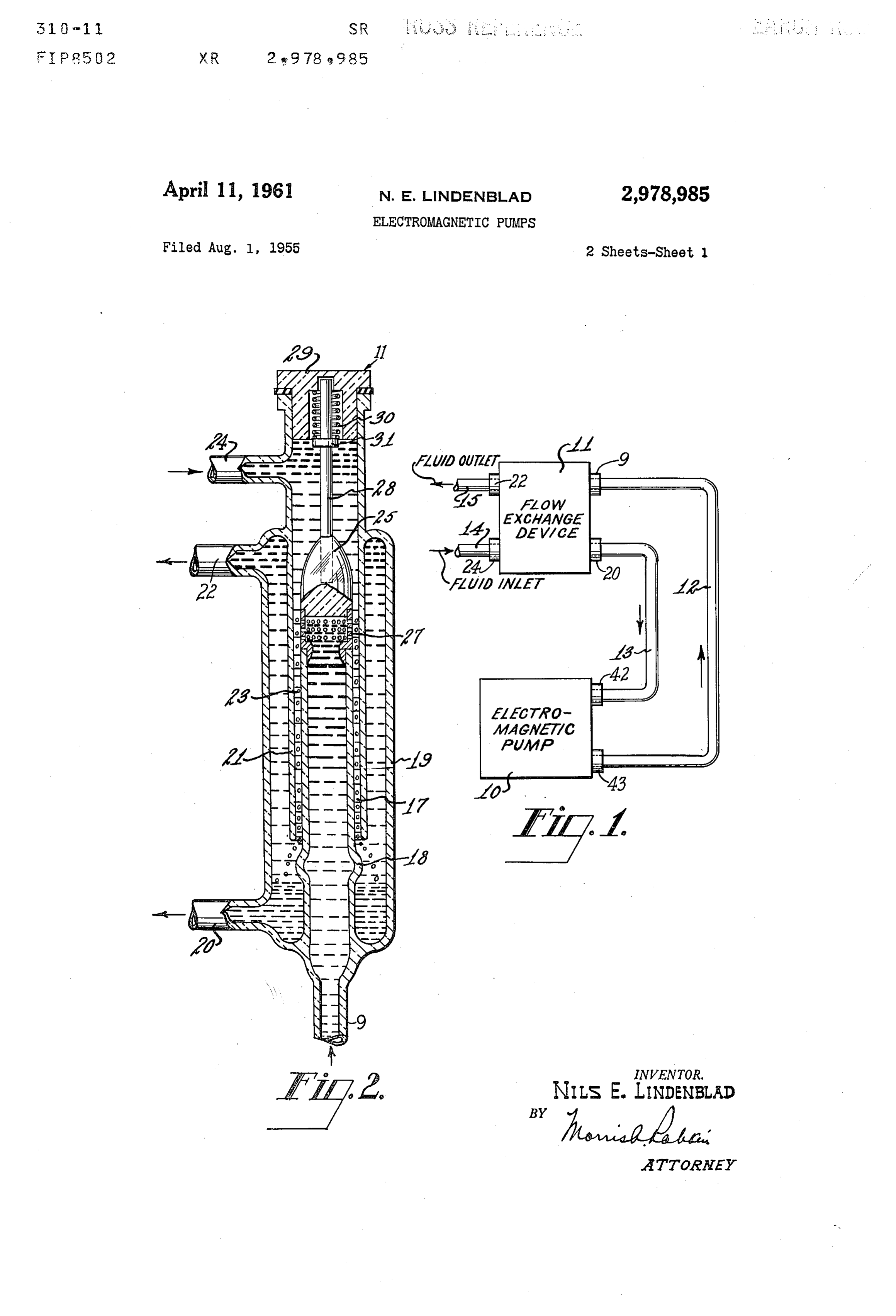
The present invention relates to an improved electro 5 provide an improved electromagnetic pump which is free magnetic pump, and is also concerned with a pumping of structural complexities and which is more economical system wherein a first liquid, which may be electromag to make than former electromagnetic pumps. netically pumped, drives a second liquid. It is another object of the present invention to provide Electromagnetic pumps are useful in pumping conduc an improved pumping system wherein a primary drive tive fluids such as liquid metals. It may be desirable, 20 fluid exchanges its flow energy with another fluid and however, to pump a nonconductive fluid electromagnet thereby applies a pressure increment thereto. ically. In a cooling system, for example, a nonconductive It is still another object of the present invention to pro fluid such as water may be found more suitable as a heat. vide an improved pumping system in which an electro transfer agent. magnetically pumped fluid drives another fluid. Some types of heretofore proposed electromagnetic 25 It is still another object of the present invention to pro pumps require provisions whereby conductive contact with vide an improved pumping system wherein a conductive the fluid is made. This is disadvantageous because con fluid exerts hydraulic pressure on, and thereby pumps, an tamination of contacts and resistive losses at the contacts other fluid having a lower specific gravity. may arise. Other types of electromagnetic pumps require Other objects and advantages of the present invention rather complicated structures so that conductive fluid may 30 will, of course, become apparent and immediately suggest be driven with a rotating magnetic field. The present in themselves to those skilled in the art to which the inven vention provides an improved electromagnetic pump tion is directed from a reading of the following specifica which eliminates the need for conductive contact with the É tion in connection with the accompanying drawing in fluid as well as the need for complex pump structures. which:
Briefly, an electromagnetic pump constructed according 35 Figure 1 is a diagrammatic showing of a pumping sys to the present invention includes an oblong closed loop tem provided by the present invention; with inlet and outlet ports for the passage of a conductive Figure 2 is a detailed view, partially in section, of one fluid to be pumped. The loop is magnetically coupled to embodiment of the flow exchange device included in a coil to which a source of alternating current is connected. Figure 1;
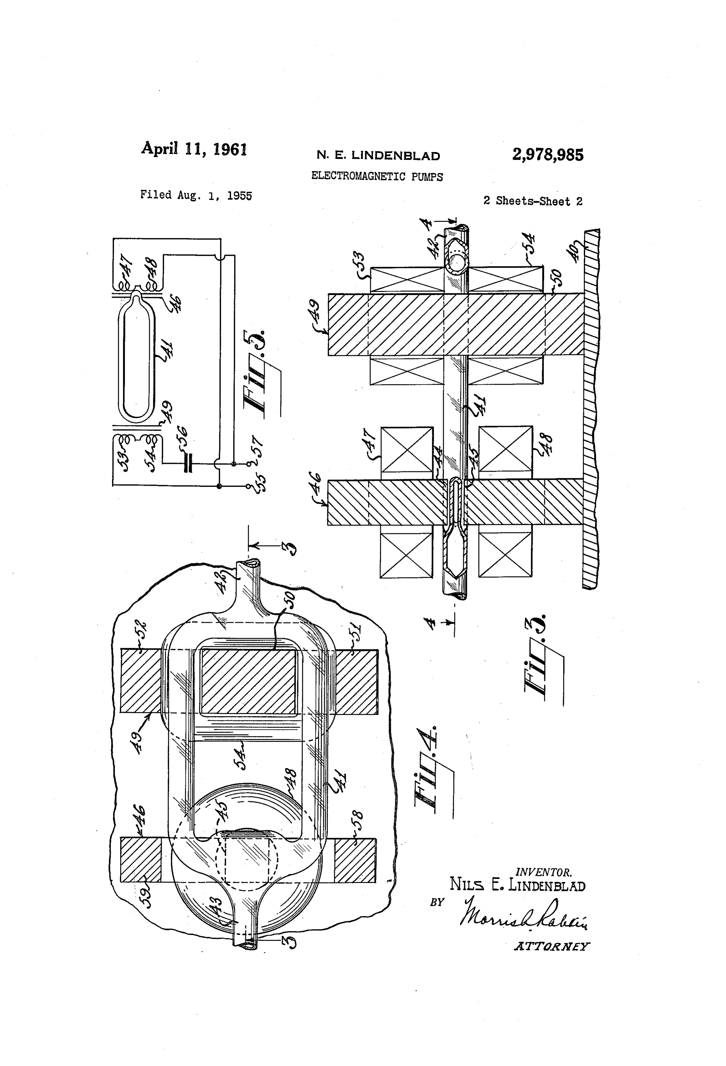
A heavy alternating current is, therefore, electromagnet 40 Figure 3 is a sectional side view of an electromagnetic ically induced in the fluid contained in the loop. Another pump constructed in accordance with the present inven alternating magnetic field that is transverse to the loop is tion, the section being taken along the line 3-3 of Fig provided near the outlet port. This last mentioned alter ure 4;
nating magnetic field interacts with the magnetic field 45 Figure 4 is a plan view, partially in section, of the elec established by the current induced into the fluid contained tromagnetic pump illustrated in Figure 3, the section being in the loop and a resultant force is applied to the fluid taken along the line 4-4 in Figure 3; and which propels it through the outlet port. The pumped Figure 5 is a schematic diagram of the electrical circuit conductive fluid may be used as a primary driving fluid of the electromagnetic pump illustrated in Figures 3 to pump, in turn, some other fluid such as a nonconductive 50 and 4.
coolant in a refrigerating system. The block diagram of Figure 1 shows a pumping system Known methods for pumping one fluid with another provided by the present invention. The basic elements fluid have not been found suitable. For example, a con of this pumping system are an electromagnetic pump 10 ductive fluid, such as mercury, has not been successfully and a flow exchange device it. The electromagnetic used as a primary drive fluid. In one known method, jets 55 pump 0 circulates a conductive fluid through the flow of the primary drive fluid must entrain the driven fluid. exchange device it. The conductive fluid, which may be Since the friction between the primary drive fluid and a liquid metal such as mercury, is pumped, in the direc the driven fluid is very small, this method has proven in tion indicated by the arrow, through an outlet port 43 efficient. Another method consists of breaking up the thereon and through one of the pipes 2 which connects flowing conductive fluid into sections in a tube, and allow 60 the electromagnetic pump 10 to the flow exchange device ing alternate sections of the driven liquid to be forced by way of the port 9. Another pipe 13, which is connected along by the weight and pressure of the conductive fluid. to the outlet port 20, receives the conductive fluid after it This method has provided only erratic pressures. has passed through the flow exchange device 11, and is The present invention possesses, in addition to features connected to the electromagnetic pump 10 which recir pointed out above, the feature of obtaining a continuous culates the fluid through an inlet port 42 thereon. flow of the driven fluid by providing a novel flow exchange 65 Another fluid circulates through the flow exchange de device. In one illustrative form of the device, the conduc vice 1. It enters the flow exchange device 11 through tive fluid, which may be pumped by the electromagnetic an inlet pipe 14 and an inlet port 24 and leaves through pump described above, is finely divided into droplets. an outlet port 22 and an outlet pipe 15. This fluid may The droplets are forced into a tube through which the be a non-conductive fluid, such as water, having a lower driven fluid flows. This finely divided conductive fluid 70 specific gravity than mercury which may be used as the provides a “rain” of conductive fluid through the driven conductive fluid. This other fluid is driven by the conduc fluid. The driven fluid is dragged along by the conductive tive fluid upon interaction therewith in the flow exchange

Page 4
3 A.
device 11 so that a difference in pressure exists between An electromagnetic pump suitable for use in connection the inlet fluid and the outlet fluid. with the flow exchange device described above is shown In Figure 2, a more detailed view of a flow exchange in Figures 3 and 4. The pump structure is supported on device constructed in accordance with the present inven a base 40. This structure comprises a loop of conduc tion is shown. This device may be an integral unit coin tive fluid which is defined by an oblong closed tube 41. Inlet and outlet ports 42 and 43, respectively, are con prising a plurality of concentric cylinders 17, 19 and 25.
These cylinders may be made of glass. However, any nected at opposite ends of the tube 41. The tube 41 suitable material which does not interact chemically withmay be made from some insulating material Such as the fluids to be handled may be used. The inner cylinder glass. However, successful operation of the electromag 17 has a bulbous portion 18 near the bottom. It is con O netic pump may be obtained if some other material is nected through a port 9 at the lower end thereof to a used, as long as the conductivity of the tube material is sorce of the primary driving fluid, which may be mer significantly less than the conductivity of the conductive cury that is pumped by an electromagnetic pump. The fluid to be confined therein. The section of the tube outer cylinder 19 is terminated near its lower extremes near the outlet port 43 may be flattened as indicated on the walls of the inner cylinder 17. Near the lower 15 on the drawing.
end of the outer cylinder, a port 20 is provided. The The poles 44 and 45 formed by an alternating current upper end of the outer cylinder 19 is terminated at the magnetic yoke structure 46 are placed on opposite sides walls of the intermediate cylinder 2A. The intermediate of this flattened section. The yoke magnetic structure is cylinder 21 extends upwardly, as viewed in the drawing, made of magnetic material such as laminated iron. A from a point over the bulbous portion 8 of the inner 20 magnetic circuit is completed through two legs 58 and 59 cylinder 17 to above the termination of the outer cylin of the yoke 46 that are disposed outside of the oblong der 19. A port 22 is connected to the intermediate cylin tube 4. A split central leg of the yoke 46 forms the der 21 near the top thereof. Another port 24 is con poles 44 and 45. An alternating magnetic field is pro nected near the upper termination of the outer cylinder vided in a gap between the adjacent faces of the poles 44 19. The intermediate cylinder 21 is not terminated at the 25 and 45. This field passes through the flattened section inner cylinder 7. However, the inner cylinder 17 and of the oblong loop 4 and is perpendicular thereto. the intermediate cylinder 21 are disposed in cooperative A coil 47 is wound around the central leg of the yoke relationship to define an elongated annular chamber 23 46 which forms the upper pole 44 to provide a winding therebetween. thereabout. Another coil 48 is wound around the sec A cap 25 is provided to seal the upper end of the inner 30 tion of the central winding leg forming the other pole cylinder i7. This cap is conical in shape and may be 45 to provide a winding thereabout. When energized made out of plastic, rubber or some other similar seal by an alternating current, these coils provide the afore ing material. An apertured cylinder 27 is inserted be mentioned alternating magnetic field between the faces of tween the cap 21 and the walls of the inner cylinder 7. the poles 44 and 45.
This apertured cylinder 27 may be provided, as illus 35 As previously mentioned, it is desirable to eliminate tratively shown, with three horizontally disposed rows of the need for conductive contact with the fluid in an elec apertures. The apertures communicate with the annular tromagnetic pump. To achieve this objective, an electric chamber 23 formed between the inner cylinder 7 and the current is induced into the conductive fluid in the oblong intermediate cylinder 21. loop defined by the tube 41 by means of electromagnetic A rod 28 is attached to the top of the conical cap 25. 40 induction. To this end, a magnetic core 49 is provided. This rod is yieldably secured to a stopper 29 which closes This core is of the closed "E' type, and may be con the top of the intermediate cylinder 25. A spring 30 is structed from laminted iron. The central winding leg supported on a shoulder 31, which is fixed to the rod 50 of the core 49 is disposed inside of the oblong loop 28. Such yieldable support means for the cap 25, as the defined by the tube 41. The outside legs 5 and 52 are spring 30, is desirable in order to prevent damage to the located outside of the loop defined by the tube 4. There cylinders 17, 19 and 21 in the event that they are con 45 fore, the core 49 encloses and threads the oblong tube structed from glass. Should a less brittle material be 41. A first coil 53 is wound around the central winding used, such yieldable support means may be eliminated, leg 50 and is disposed above the oblong loop 41. Another and the cap 25 and the apertured structure 27 may be coil 54 is wound around the central winding leg 50 and made as an integral part of the inner cylinder 17. is disposed below the oblong loop defined by the tube 41. During the operation of the flow exchange device, the 50 It will be observed that these coils 53 and 54 will be primary driving fluid is pumped, by an electromagnetic magnetically linked with the oblong loop 41 and provide pump for example, upwardly into the inner cylinder 17 for the induction of an alternating current into the con through the port 9. This fluid passes through the aper ductive fluid therein.
tured cylinder 27 and flows, in the form of finely divided The interconnection of the coils and the circuit diagram droplets, through the annular gap 23 provided between 55 of the electromagnetic pump described in Figures 3 and the cylinders 17 and 2. The driven fluid, which may 4 is shown in Figure 5. The coils 53 and 54 which are be Water, enters the intermediate cylinder 21 through the disposed on the core 49 are connected in series. The upper port 24 therein. This fluid fills the annular cham Outer end of one of these coils 53 is connected to a ter ber 23 and flows upwardly through the chamber formed minal 55 and the outer end of the coil 54 is connected between the intermediate cylinder 21 and the outer cylin O through a capacitor 56 to another terminal 57. The der 19 to the port 22 located near the top of the outer terminals 55 and 57 are available for connection to a cylinder 9. The droplets of primary drive fluid flow Source of alternating current (not shown). These ter downwardly through the driven fluid and drag the driven minals 55 and 57 are also connected to opposite ends of fluid along. This interaction between the droplets and the serially connected coils 47 and 48, which are dis the driven fluid gives a downward motion of flow to the 65 posed upon the yoke 46, and provide the magnetic field driven fluid. This motion results in a hydraulic pressure across the loop defined by the tube 4. upon the driven fluid. When an alternating voltage is applied across the ter The droplets flow around the bulbous portion E8 of the minals 55 and 57, the coils 53 and 54 are energized. An inner cylinder 17. The driven fluid and the primary alternating current is induced into the conductive fluid drive fluid, which may be water and mercury, respec 70 in the loop defined by the tube 41 by electromagnetic tively, separate because of their difference in specific induction. The fluid in the loop defined by the tube 4. gravity. The primary drive fluid flows out of the port forms a short circuit secondary as in a transformer. 20 at the bottom of the outer cylinder 19 and may be Therefore, a current of large magnitude is induced into recirculated by means of an electromagnetic pump which the conductive fluid in the loop. This current circulates is provided in accordance with the present invention. 5 around the loop and flows in a direction perpendicular
Page 5
to the direction of the alternating magnetic field which is netic core structure having a centrally located winding provided by the coils 47 and 48 in the yoke structure 46. leg, said loop being disposed around said winding leg The magnetic field produced by the current in the fluid whereby said leg threads said loop, a coil wound around conductor interacts with the alternating magnetic field said winding leg, means electrically coupled to said coil provided between the poles 44 and 45, in well known for applying alternating voltages across said coil whereby manner, to produce a motor action which propels the an alternating current is induced around said loop into conductive fluid through the port 43. said fluid in said loop, and means disposed adjacent said The proper phase relationship must exist between the outlet port for providing a magnetic field perpendicular alternating current and the alternating magnetic field to and intersecting said loop, said field being located ad provided in the yoke 46 in order to develop a force to O jacent to said outlet port so that said fluid is propelled propel the conductive fluid through the outlet port 43. through said outlet port,
The alternating current should attain substantially max 4. An electromagnetic pump comprising means for imum amplitude at the same time as the alternating mag confining a conductive fluid in a closed loop, said loop netic field attains maximum amplitude. Therefore, the having a pair of ports for entry and exit of said fluid, alternating current must be substantially either in phase 5 means magnetically coupled to said loop for generating or 180° out of phase with the alternating magnetic field, an alternating magnetic field and inducing an alternating depending upon reference direction selected for zero current around said loop into said fluid in said loop, and phase difference. The alternating current in the conduc means operatively associated with said loop near said tive fluid and the alternating magnetic field are both exit port for generating another alternating field which is produced by electromagnetic action. Due to differences 20 near said exit port and oriented transversely to said loop, in the magnetic circuit leakage and due to different load said other alternating magnetic field being in phase with resistivities, an out of phase condition occurs which may said current around said loop whereby said fluid entering easily be corrected. A capacitor, such as the capacitor said entry port is propelled out of said exit port. 56, may be connected in series with the coils 53 and 54. 25 5. An electromagnetic pump for a conductive fluid The value of this capacitor 56 is selected to shift the which comprises means establishing a closed loop path. phase of the induced current and provide exactly the for said fluid, said means having an entrance and an proper in phase relationship between the alternating exit, means propelling said fluid along said first named current in the loop 41 and the transverse alternating means in said loop path from said entrance to said exit magnetic field in the propulsion region. including means inducing an alternating current around When utilized in a pumping system such as shown in 30 said loop path in said fluid in said loop path, and means Figure 1, the inlet port 42 may be connected to the pipe operatively associated with said first named means and 13 and the outlet port 43 may be connected to the other disposed transversely to said loop path and generating an pipe 12. alternating magnetic field which interacts with said What is claimed is: current.
1. An electromagnetic pump comprising means for di 6. An electromagnetic pump for a conductive fluid recting a conductive fluid in a closed loop, inlet and outlet which comprises means establishing a closed loop path ports communicating with said loop, a winding mag for said fluid, said means having an entrance and an exit, netically linked with said loop, means coupled to said and means propelling said fluid along said means in said winding for applying alternating current to said winding loop path from said entrance to said exit including means for inducing an alternating current around said loop into 40 inducing an alternating current around said loop in said said fluid in said loop, and means disposed adjacent to fluid in said loop whereby to set up a first alternating said loop near said outlet port for providing an alternat magnetic field about said loop, and means operatively ing magnetic field transversely to said loop near said associated with said first named means and generating a outlet port for propelling said fluid through said outlet 45 Second alternating magnetic field which intersects said port. loop path adjacent said exit and interacts with said first 2. An electromagnetic pump comprising a closed loop magnetic field.
conduit having inlet and outlet ports connected thereto, a conductive fluid contained in said conduit, a winding References Cited in the file of this patent magnetically linked with said conduit, means coupled to 50 UNITED STATES PATENTS said winding for applying alternating current to said 1,298,664 Chubb ----------------- Apr. 1, 1919 winding to induce alternating current around said loop 1,698,619 Blow ------------------ Jan. 8, 1929 into said conductive fluid, a yoke structure constructed 1,736,643 Beck ----------------- Nov. 19, 1929 of magnetic material and including a pair of poles form 1,792,449 Spencer --------------- Feb. 10, 1931 ing parallel, spaced pole faces having a gap therebetween, 55 2,159,179 Ringgenberg ----------- May 23, 1939 said pole faces being disposed parallel to said loop con 2,263,864 Avigdor -------------- Nov. 25, 1941 duit and adjacent to said outlet port, and means for 2,397,785 Friedlander ------------- Apr. 2, 1946 establishing an alternating magnetic field in said yoke 2,612,109 Wakefield ------------- Sept. 30, 1952 structure between said pole faces which is in phase with 2,652,778 Crever --------------- Sept. 22, 1953 said alternating current in said conductive liquid. 60 2,658,452 Donelian ------------- Nov. 10, 1953 3. An electromagnetic pump comprising a conductive 2,787,219 Werner ---------------- Apr. 2, 1957 fluid, means providing a passage in the form of an ob long, closed loop for containing said conductive fluid, FOREIGN PATENTS inlet and outlet ports connected to said loop to provide 698,623 Great Britain ----------- Oct. 21, 1953 for the passage of said fluid through said loop, a mag
Provenance
- Collection
- Cited prior art
- Original PDF
- patentimages.storage.googleapis.com →
- Filed
- 1955-08-01
- Pages
- 5
- Method
- pdftotext (the PDF's own text layer) + pdftoppm 300dpi page scans
- Source
- Google Patents bibliographic record
- Granted
- 1961-04-11
- Inventors
- Nils E Lindenblad; RCA Corp
- Transcribed from
- patentimages.storage.googleapis.com →