patent · US1446736
Manufacture of hydrogen and oxygen
27 February 1923
Page 1
Drawing sheet — no readable text.
Page 2
Drawing sheet — no readable text.
Page 3
Patented Feb. 27, 1923. 1,446,736
FARLEY GRANGER CLARK, OF TORONTO, oNTARIO, CANADA.
MANUEFACTURE OF HYDROGEN AND OXYGEN.
Application filed August 29, 1919, Serial No. 320,724. Renewed March 21, 1921. Serial No. 453,990. To all whom it may concern: gases from between the active faces of the Be it known that I, FARLEY GRANGER electrodes.
CLARK, citizen of the United States, resid view of theThis is especially important in ing at Toronto, county of York, Province evolution due to the increased greatly rate, of gas higher current densi 60 of Ontario, Canada, have invented certain ties. I therefore employ electrodes perme new and useful Improvements in the Manu facture of Hydrogen and Oxygen; and I do able that by the evolved gases and so arranged electrolyte may circulate freely upward hereby declare the following to be a full. in planes somewhat to the rear of but ad clear, and exact description of the inven 0 tion, such as will enable others skilled in jacent to the active electrode faces. By em 65 the art to which it appertains to make and of ploying electrodes of this character, passage use the same. the gas rearward as well as upward is facilitated,
This invention relates to the manufacture fects are avoided. and excessive polarization ef of hydrogen and oxygen; and it has to do The expression "perme 5 more particularly with a method of produc able electrode' is here used in a broad sense 70 ing hydrogen and oxygen by electrolytic de terial or having such mechanicalof construc to denote an electrode composed such ma composition of water wherein substantially tion that gas may pass rearward from its higher current densities are employed than front or active face. That is, the material have been employed heretofore for this pur 30 pose, thus enabling large increase in the composing the electrode may itself be suffi 75 rate of output per unit area of electrolyte ciently rectly porous to permit passage of gas di therethrough; or the electrode may cross section between electrodes. .
Electrolytic decomposition of water for made of wire mesh or ofcasemetal be apertured, as in the of electrodes strips, in production of hydrogen and oxygen has 25 been characterized heretofore by the em such manner as to facilitate such passage. 80 ployment of relatively very low current as Itclose is desirable also that the electrodes be together as practicable. In prac densities, generally not exceeding 0.2 or 0.25 tice find it advisable to have them not . ampere per square inch of projected elec more than one-fourth of an inch apart; and trode area. There have been occasional 30 proposals to operate at as high as 0.5 ampere a smaller spacing distance, say one-eighth
density; but so far as I am aware, such of an inch, is distinctly better. Where the proposals have never been favorably enter hydrogen and oxygen are to be separately tained in the practical art. This is ap diaphragm is employment collected, the of a separating parently because certain complications at non-conducting diaphragm necessity.
tending operation at high current densities be of porous material suitably resistantmay be used, it
under the conditions heretofore suggested, the action of the electrolyte, such as woven have had the effect of discouraging attempts asbestos cloth about one-eighth of an inch in this direction. After extensive investi thick; and in such case, the electrodes may gation of the subject, however, I have found 40 that under proper conditions, to be set forth directly engage the opposite sides of the 85 diaphragm.
hereinafter, operation at current densities In practicing the invention it is very de greatly in excess of those commonly used sirable to operate with the elctrolyte rela prior to my invention is not only feasible tively hot, since not only does this increase but offers certain distinct advantages 45 dition to augmenting the rate of output.
in ad the conductivity of the electrolyte and thus 06) require the application
In order to establish the conditions nec pass a given volume of current of less voltage to essary to operate successfully at the rela otherwise be necessary, but alsothan would tively high current, densities here in ques has the additional function of greatly faciliit because tion, it is essential to properly correlate tating prompt disengagement of the gener 05 50 character and spacing apart of electrodes, ated gas from the electrodes, and rapid sep with operating temperature of electrolyte. aration
It is in the discovery of this relation and trolyte. ofThetheelectrolyte gas bubbles from the elec its utilization in a practical process that the solution of a base or anemployed acid. A is a water solution present invention largely consists, of caustic soda, containing about 17 percent 0 55 Provision should be made to facilitate dis NaOH offers certain advantages and is at engagement and removal of the generated present preferred, Maintenance of the elec
Page 4
trolyte at the desired high temperature can in view, 10 are cell walls provided with dou ble flanges 11, between which flanges are in be effected wholly or largely through the serted heat developed by the passage of the current phragmsthe 12,margins of asbestos cloth dia therethrough; and to this end the electrolyz Eightly clampedthetogether assemblage being held 70 ing cell or cells may be heat insulated to sulated coupling bolts 13, bypassing means of in through minimize heat losses by radiation, etc. For apertured lugs 14 with which the flanges of good results the temperature of the elec the end cell walls are provided. Carried on trolyte should be at least 50° or 60° C. in distributing bars 15, which in turn are sup practicing the present method, and higher 10 temperatures, up to say 95° C. or there ported on the cell walls by means of brack
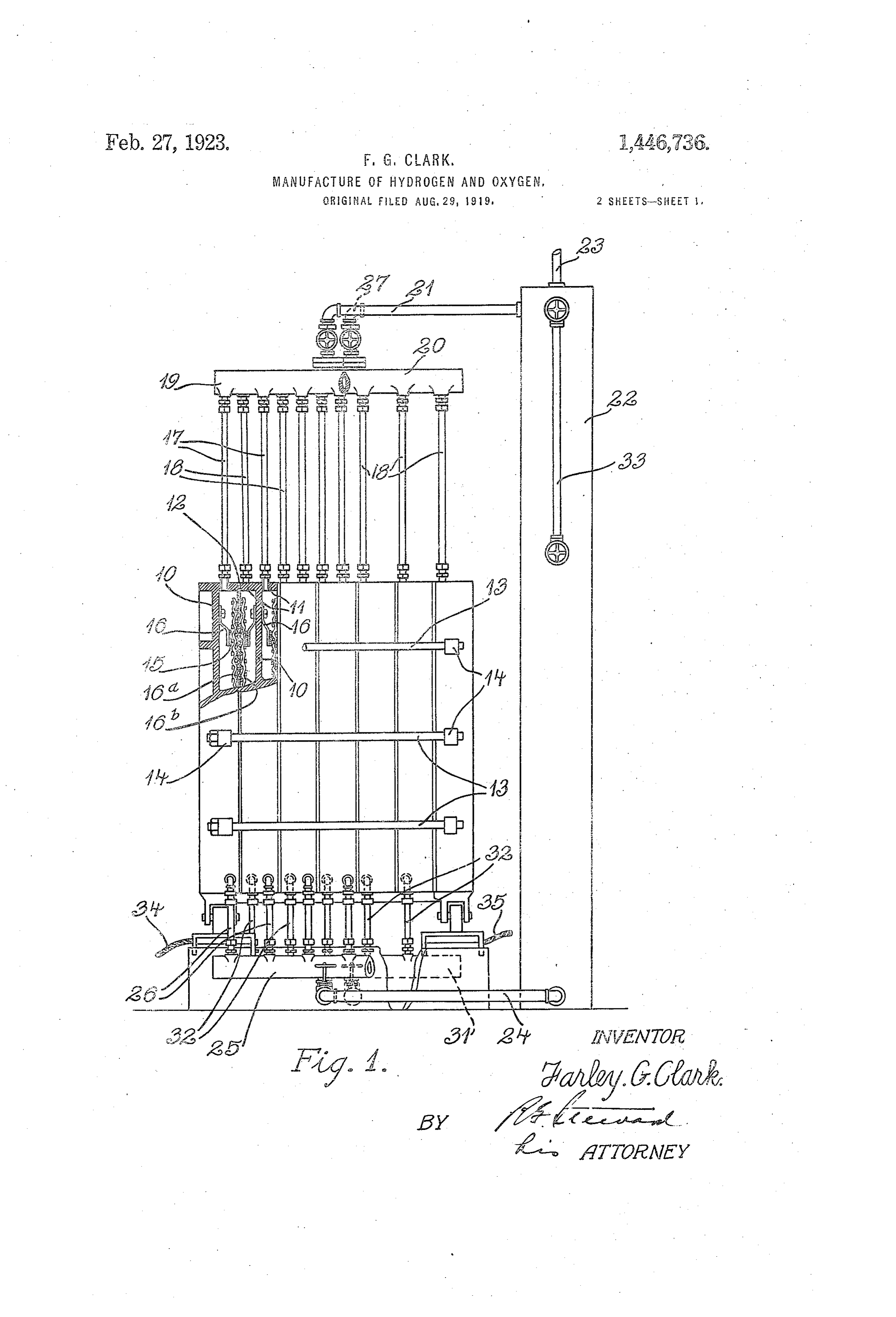
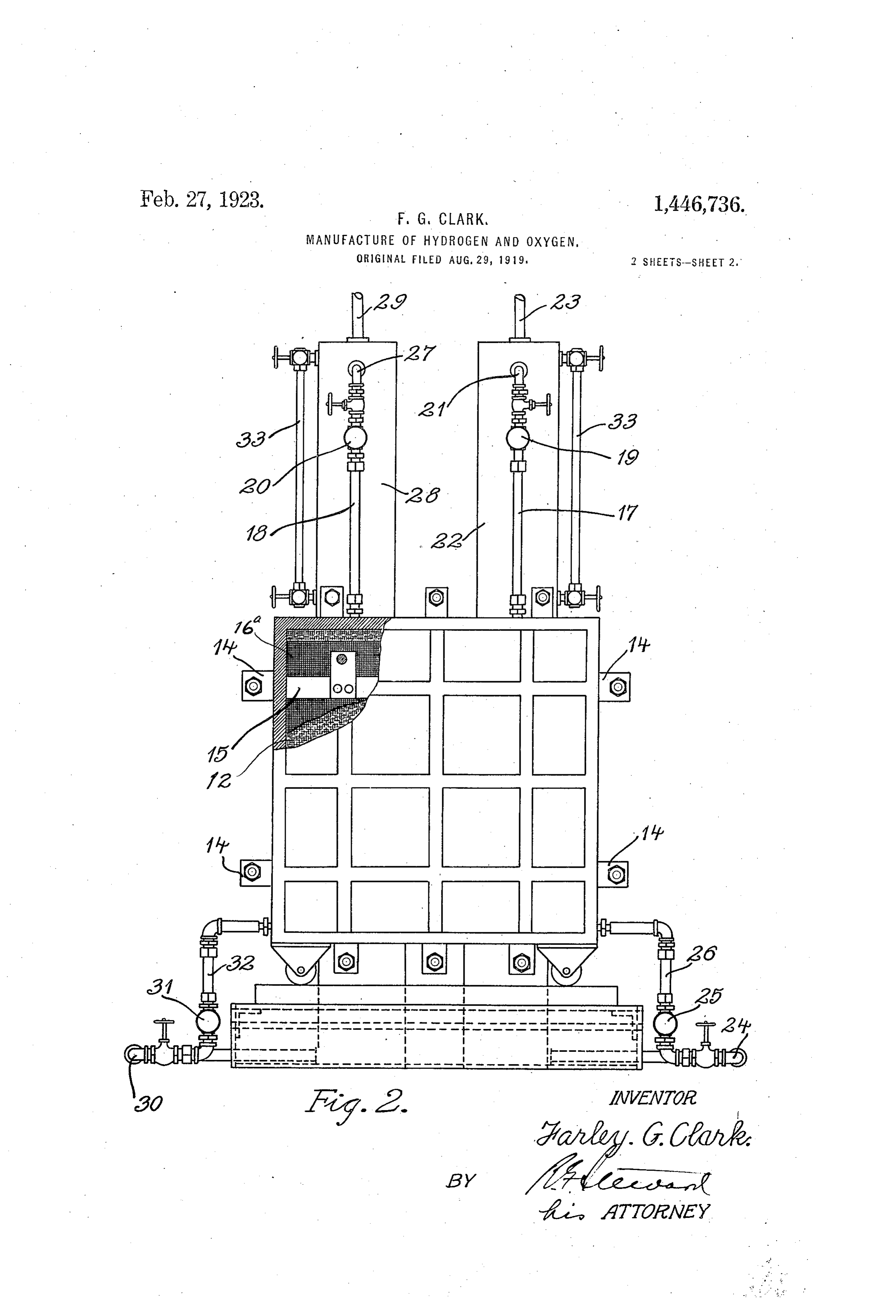
ets 16, are the permeable or foraminous abouts are often to be recommended, these trode members 16 and 16 of each cooperat elec higher temperatures being especially effec tive in ensuring very rapid passage of gas ing couple. In this instance, these electrode bubbles through and from the electrolyte. members and it consist of metallic wire mesh fabric, 80 will be seen that by means of the de 15 In any case the temperature should be some what below the boiling point of the elec scribed arrangement they are supported in such manner that they lie substantially trolyte at the operating pressure, in order against opposite sides of the separating dia to avoid excessive energy losses by genera tion of steam. The normal boiling point of phragm and are spaced away from the re 20 the electrolyte may be increased by operat spective cell walls, leaving space for free 85 ing under pressure, thus making possible the circulation of electrolyte and for passage of employment of still higher current densi gas between each said electrode member and ties; but I consider operation at about ordi the corresponding cell wall upon which it is nary atmospheric pressure more desirable mounted. Gas and electrolyte offtakes 17 25 in practice. Within limits, the temperature and 18 connect each half-cell with headers 19 90 of the electrolyte can be varied by varying and 20, respectively. Assuming 16 to be an the operating voltage. An increase in volt odes and 16 to be cathodes, in the assemblage age increases the current flow and also the of bi-polar electrodes in this filter press type heating effect, thus raising the temperature of construction, anolyte and oxygen pass up 30 of the electrolyte. But this decreases the re ward through offtakes 17 into header 19; 95 sistance of the electrolyte and consequently while catholyte and hydrogen pass upward further increases the current; so that the through offtakes 18 into header 20. From effect is cumulative. A condition of equi header 19 anolyte and oxygen pass through librium is of course attained when the heat conduit 21 into a separating tank 22, in the 35 losses by radiation, etc., overbalance the gen upper part of which oxygen collects and is 00 eration of heat by the current. conducted through outlet 23 to any suitable At present I consider operation at from place of storage or use; while the separated say 15 to 3 amperes per square inch of pro electrolyte is, led back through conduit 24 jected electrode area that is, of the cross sec from the base of the separating tank into a 40 tion of the current path between cooperating header or manifold 25, and thence through '05 electrodes of a couple especially desirable in individual pipes 26, into the lower part of carrying out the new method herein de each anode compartment or cell. Similarly, Scribed. If densities as high as 4 or 5 am hydrogen and catholyte pass from header or peres or more per sq. inch are used it is gen manifold 20 through conduit 27 into the up O 45 erally necessary to ensure rapid circulation per part of separating tank. 28, hydrogen be: of the electrolyte as by means of a pump, ing led away through outlet pipe 29, and for example." electrolyte being returned through pipe 30, While the method may be carried out in manifold 31, and individual pipes 32, into any suitable electrolyzing apparatus of the the lower parts of each cathode compartment 5 50 general type above referred to, reference is or half-ceil. The separating tanks are pro here made, for the sake of an example, to U. vided with gage glasses 33 as shown. The S. Patent No. 1269,566 to MacDougall and various intakes and offtakes should be suit Middleton, as disclosing one form present of ap ably insulated from the main cell structure;
paratus by means of which the and the offtakes 17, 18, may desirably be of 120 55 method may be practiced. such relatively small diameter as compared An example of apparatus suitable for this to their length as to utilize the lifting effect purpose is illustrated in the accompanying of the evolved gases to induce rapid circula drawings, in which tioh of both anolyte and catholyte through Fig. 1 is a side elevation, partly broken the cell compartments. Current leads 34,35 25 60 away, and in section, illustrating a complete are provided for connection to suitable sup installation,
Fig. 2 is anandend view, also partly broken In a typical instance, using a 17 per cent
away and in section. caustic soda electrolyte maintained at about Referring to the drawings, which illus 75° to 85°C., and with an asbestos cloth dia 35 trate a 6-cell unit suitable for the purposes phragm spacing the electrodes one-eighth 130
Page 5
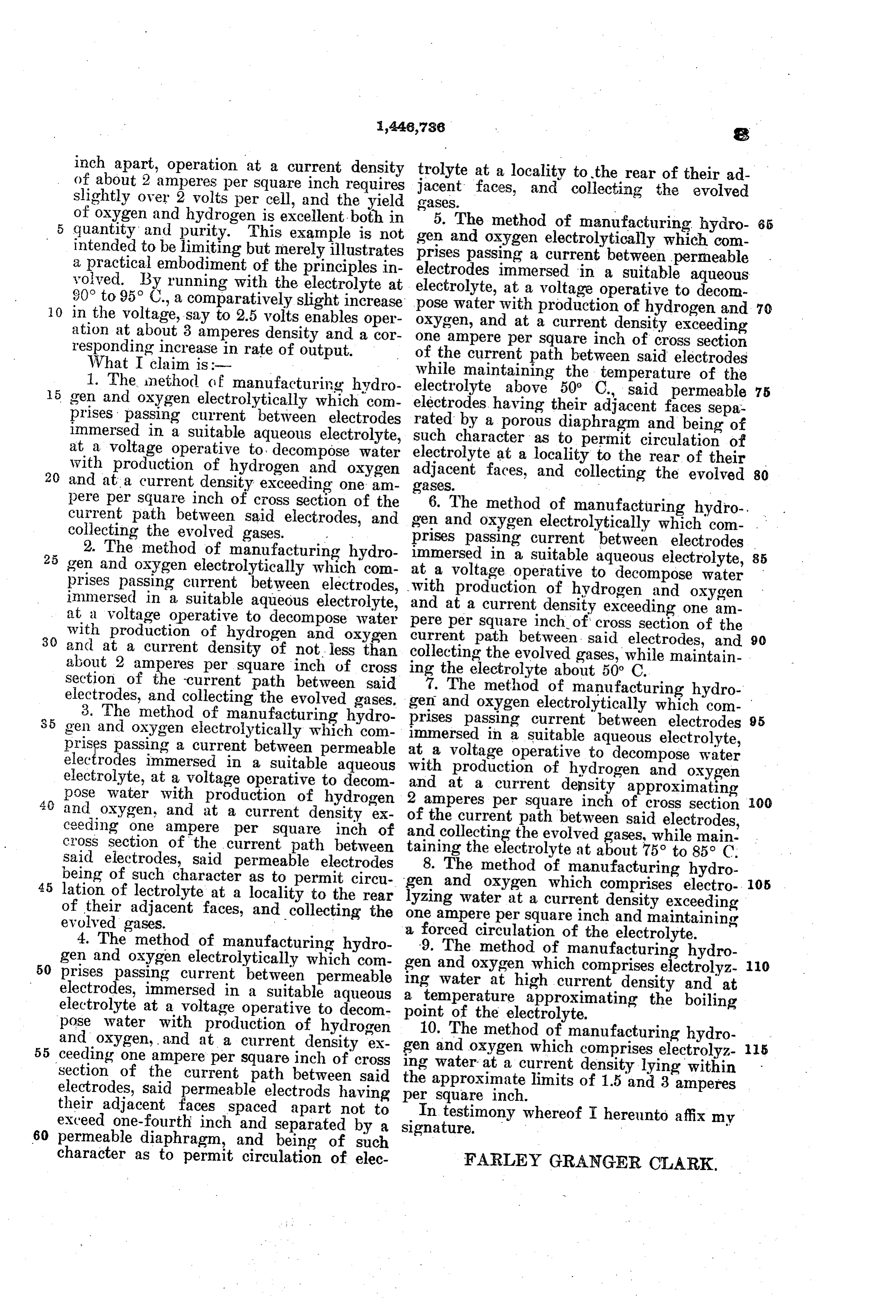
inch apart, operation at a current density trolyte at a locality to the rear of their ad of about 2 amperes per square inch requires jacent faces, and collecting the evolved slightly over 2 volts per cell, and the yield gases.
of oxygen and hydrogen is excellent both in 5. The method of manufacturing hydro 65 quantity and purity. This example is not gen and oxygen electrolytically which com intended to be limiting but merely illustrates prises passing a current between permeable a practical embodiment of the principles in electrodes volved. By running with the electrolyte at electrolyte, immersed at a in a suitable aqueous voltage operative to decom 90° to 95 C., a comparatively slight increase 0. in the voltage, say to 2.5 volts enables oper pose water with production of hydrogen and 70 oxygen, and at a current ation at about 3 amperes density and a cor one ampere per square inch of cross density exceeding responding increase in rate of output. section What I claim is:- of the current path between said electrodes 1. The method of manufacturing hydro electrolyte while maintaining the temperature of the gen and oxygen electrolytically which com electrodes having above 50° C., said permeable 75 prises passing current between electrodes rated by a poroustheir adjacent faces sepa diaphragm and being of immersed in a suitable aqueous electrolyte, such character as to permit circulation of at a voltage operative to decompose water electrolyte at a locality to the rear of their with production of hydrogen and oxygen 20 and at a current density exceeding one am adjacent faces, and collecting the evolved 80 gases.
pere per square inch of cross section of the 6. The method of manufacturing hydro current path between said electrodes, and gen and oxygen electrolytically which com collecting the evolved gases. prises passing current between electrolyte, electrodes 2. The method of manufacturing hydro immersed in a suitable aqueous
gen and oxygen electrolytically which com at a voltage operative to decompose water 85 prises passing current between electrodes, with production of hydrogen and oxygen immersed in a suitable aqueous electrolyte, and at a voltage operative to decompose water pere at per a current density exceeding one am square inch of cross section of the
with production of hydrogen and oxygen current path between said electrodes, and 90 and at a current density of not less than collecting the evolved gases, while maintain about 2 amperes per square inch of cross ing the electrolyte about 50° C. section of the current path between said 7. The method of manufacturing hydro electrodes, and collecting the evolved gases. gen and oxygen electrolytically which com 3. The method of manufacturing hydro gen and oxygen electrolytically which com prises immersed passing current between electrodes 95 in a suitable aqueous electrolyte, prises passing a current between permeable at a voltage operative to decompose water electrodes immersed in a suitable aqueous with production electrolyte, at a voltage operative to decom and at a currentof density hydrogen and oxygen pose water with production of hydrogen 2 amperes per square inch ofapproximating and oxygen, and at a current density ex of the current path between saidcross section 00 electrodes, ceeding one ampere per square inch of cross section of the current path between and collecting the evolved gases, while main said electrodes, said permeable electrodes 8. Thethemethod taining electrolyte at about 5 to 85°C.
of manufacturing hydro being of such character as to permit circu 45 lation of lectrolyte at a locality to the rear gen and oxygen which comprises electro 05 of their adjacent faces, and collecting the one lyzing water at a current density exceeding evolved gases. ampere per square inch and maintaining 4. The method of manufacturing hydro -9. The circulation a forced of the electrolyte.
method of manufacturing hydro gen and oxygen electrolytically which com 50 prises passing current between permeable gen and oxygen which comprises electrolyz 0 electrodes, immersed in a suitable aqueous aingtemperature water at high current density and at approximating the boiling electrolyte at a voltage operative to decom point of the electrolyte.
pose water with production of hydrogen 10. The method of manufacturing hydro and oxygen, and at a current density ex 55 ceeding one ampere per square inch of cross gen and oxygen which comprises electrolyz 5 ing water at a current section of the current path between said the approximate limits of 1.5 and 3amperesdensity lying within electrodes, said permeable electrods having their adjacent faces spaced apart not to perInsquare inch.
testimony whereof I hereunto affix my exceed one-fourth inch and separated by a signature.
60 permeable diaphragm, and being of such character as to permit circulation of elec FARLEY GRANGER CLARK.
Provenance
- Collection
- Cited prior art
- Original PDF
- patentimages.storage.googleapis.com →
- Filed
- 1919-08-29
- Pages
- 5
- Method
- pdftotext (the PDF's own text layer) + pdftoppm 300dpi page scans
- Source
- Google Patents bibliographic record
- Granted
- 1923-02-27
- Inventors
- Clark Farley Granger
- Transcribed from
- patentimages.storage.googleapis.com →