patent · US20070111147A1
High - voltage discharging reactor processing exhausted hydrogen gas
17 May 2007
Page 1 — bibliographic record
(19) United States (12) Patent Application Publication (10) Pub. No.: US 2007/0111147 A1
Tzeng et al. (43) Pub. Date: May 17, 2007 (54) HIGH - VOLTAGE DISCHARGING (21) Appl. No.: 11/260,427
REACTOR PROCESSING EXHAUSTED
HYDROGEN GAS (22) Filed: Oct. 28, 2005 (75) Inventors: Chih-Ching Tzeng, Yonghe City (TW);
Den-Lian Lin, Longtan Township Publication Classification (TW); Shiaw-Huei Chen, Yonghe City
(TW); Ming-Song Yang, Taipei City
(TW); Jyh-Ming Yan, Lujhu Township (51) Int. Cl.
(TW); Yuh-Jeng Yu, Longtan Township FOIN 3/00 (2006.01) (TW) (52) U.S. Cl. ................................................. 431/5: 422/168 Correspondence Address:
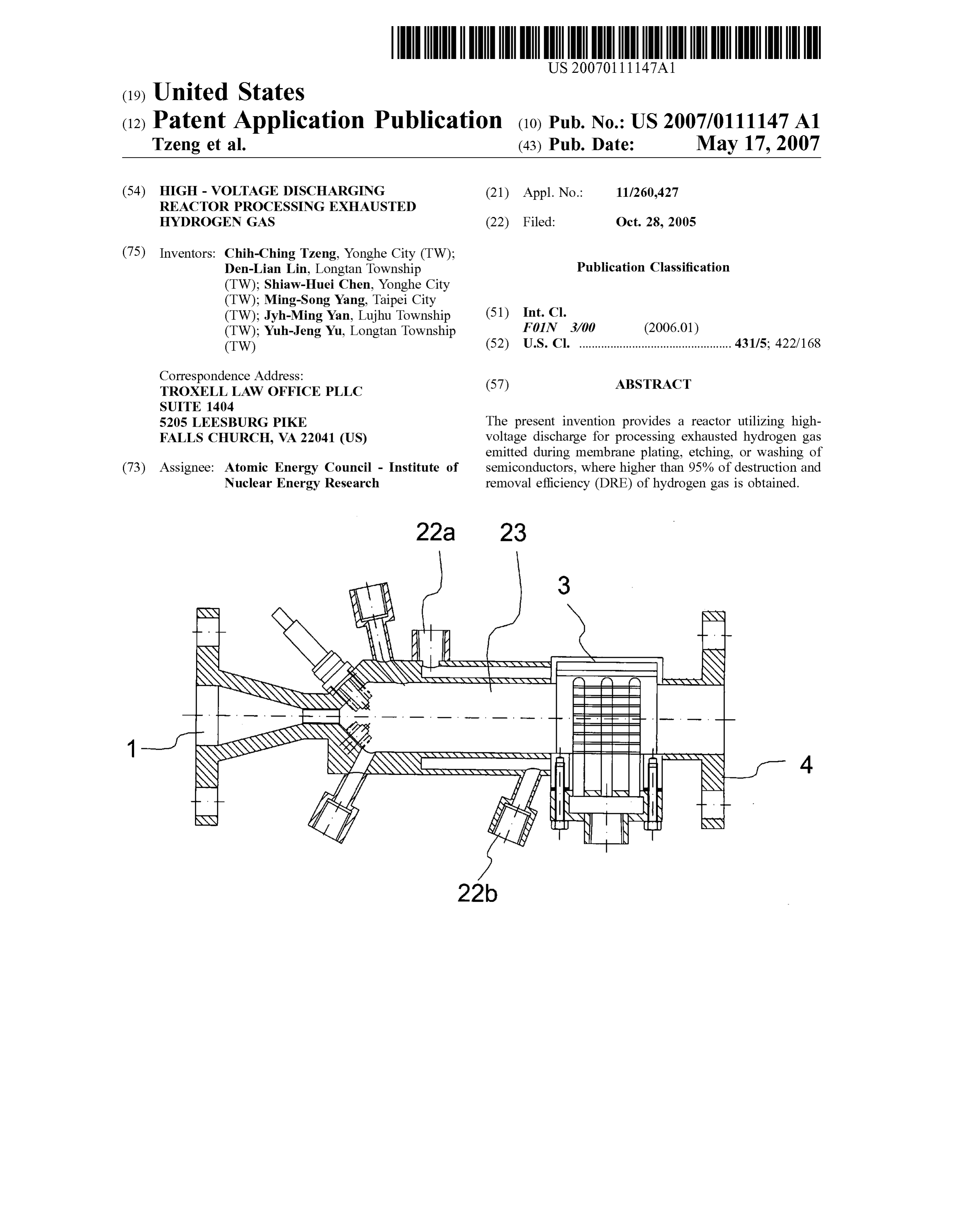
TROXELL LAW OFFICE PLLC (57) ABSTRACT
S2O5 LEESBURG PIKE The present invention provides a reactor utilizing high FALLS CHURCH, VA 22041 (US) Voltage discharge for processing exhausted hydrogen gas emitted during membrane plating, etching, or washing of (73) Assignee: Atomic Energy Council - Institute of semiconductors, where higher than 95% of destruction and Nuclear Energy Research removal efficiency (DRE) of hydrogen gas is obtained.
Page 2
Drawing sheet — no readable text.
Page 3
Drawing sheet — no readable text.
Page 4
Drawing sheet — no readable text.
Page 5
US 2007/011 1147 A1 May 17, 2007
HIGH - VOLTAGE DISCHARGING REACTOR BRIEF DESCRIPTION OF THE DRAWINGS
PROCESSING EXHAUSTED HYDROGEN GAS
0006 The present invention will be better understood
FIELD OF THE INVENTION
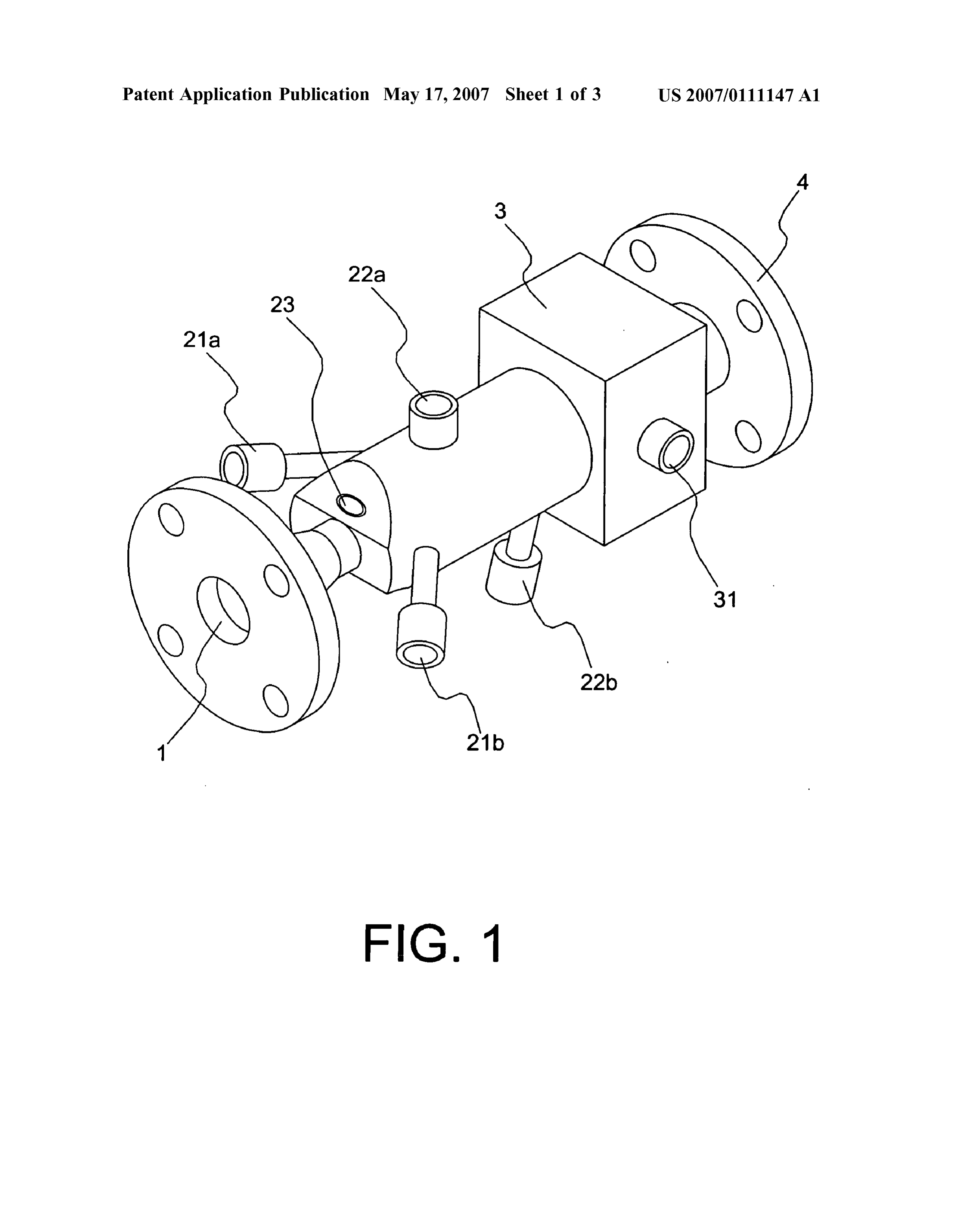
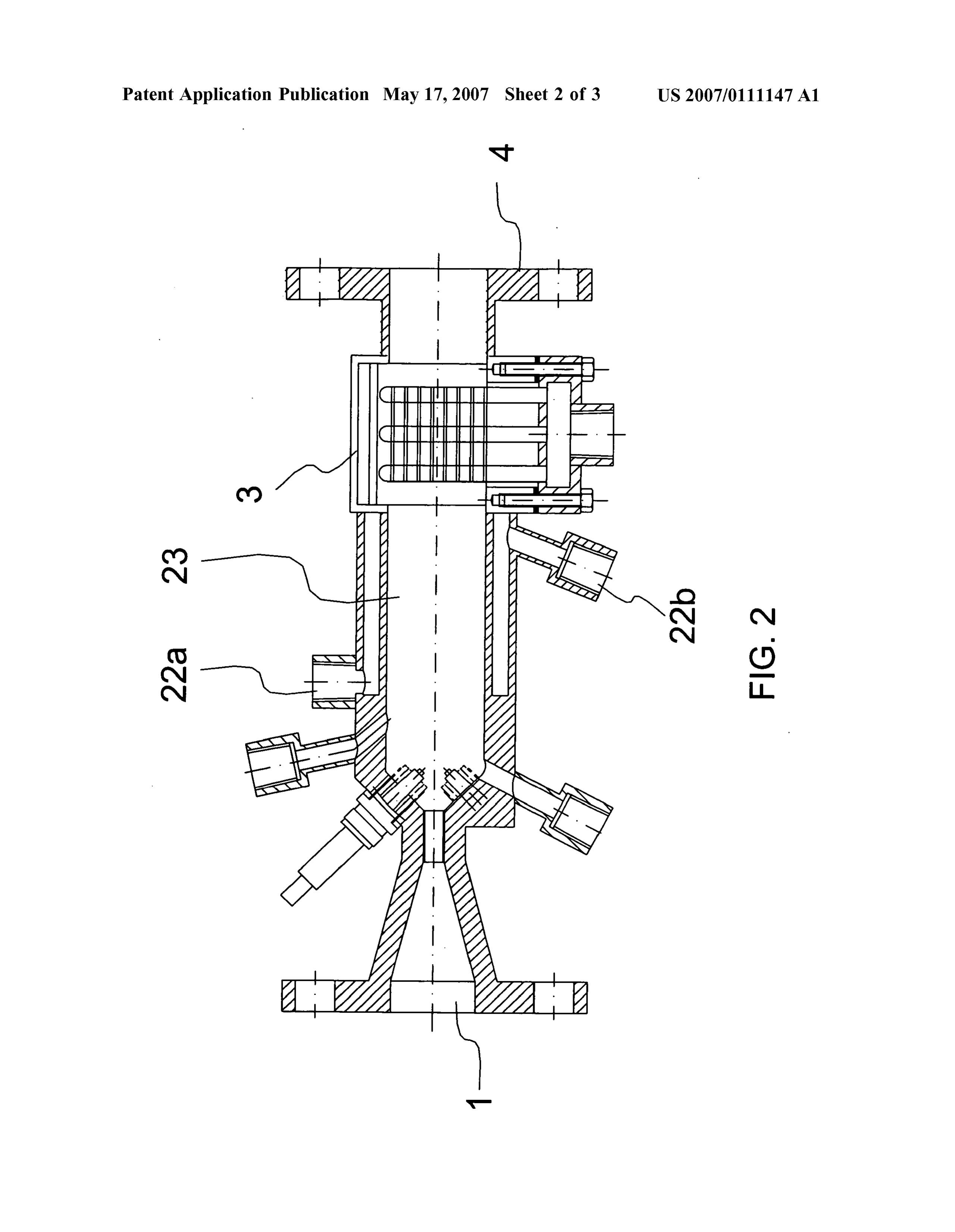
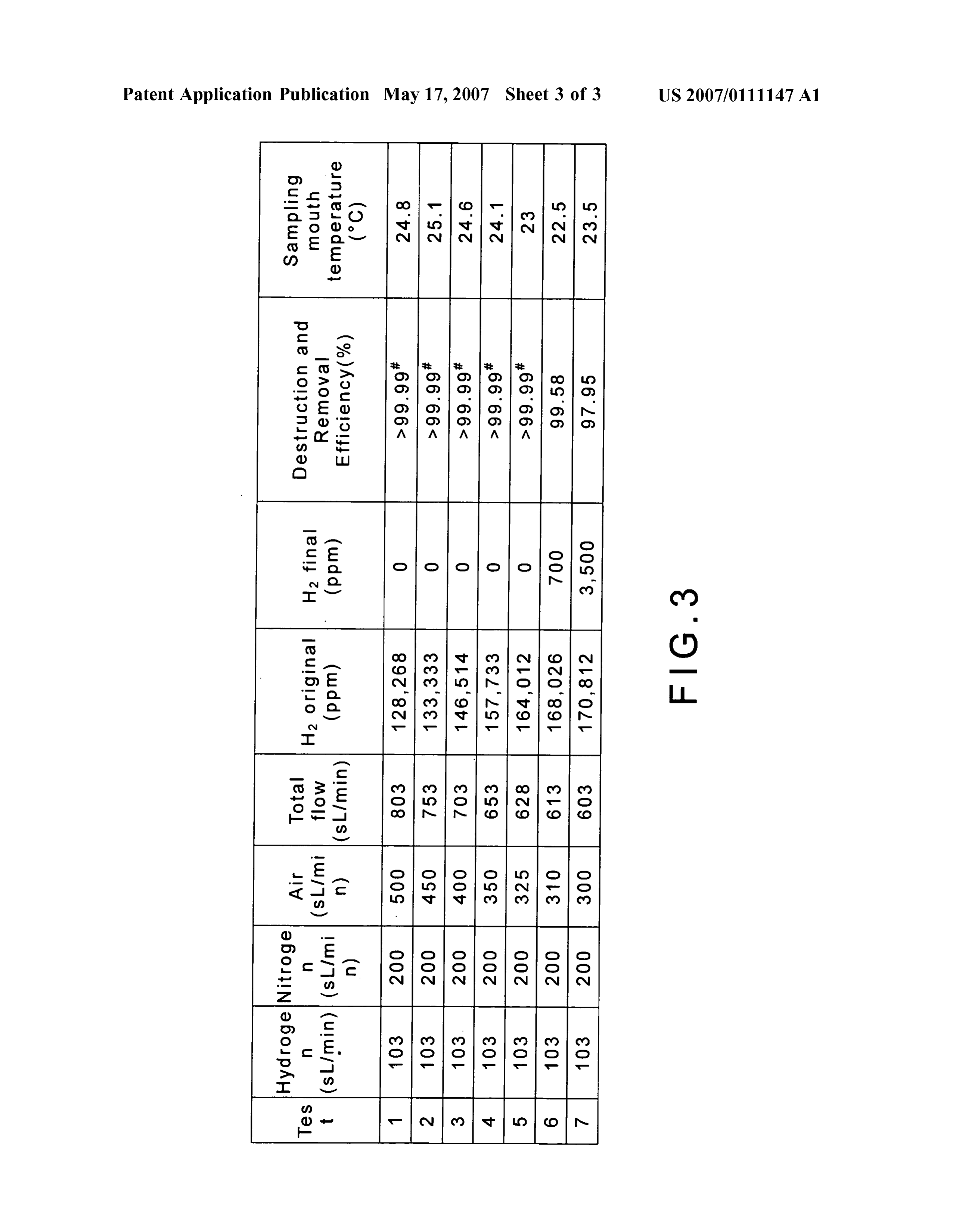
from the following detailed description of the preferred embodiment according to the present invention, taken in 0001. The present invention relates to a reactor; more conjunction with the accompanying drawings, in which particularly, relates to using a hydrogen igniting device, 0007 FIG. 1 is a perspective view of a preferred embodi which comprises two spark igniting plugs powered by an ment according to the present invention; alternating high-voltage power Supplier and is connected with a cooling device and a metal cone for preventing 0008 FIG. 2 is a sectional view of the preferred embodi backflow of gas, to process exhausted hydrogen gas during ment according to the present invention; and membrane-plating, etching, or cleaning of semiconductor 0009 FIG. 3 is a table showing the relation between the chip manufacturing processing. destruction and removal efficiency (DRE) of hydrogen and the airflow rate according to the present invention.
DESCRIPTION OF THE RELATED ART
DESCRIPTION OF THE PREFERRED
0002. In the atmosphere, normally hydrogen gas occupies EMBODIMENT only around 500 ppb. The hydrogen gas can be easily burned or even exploded, where its lowest burning temperature is 0010. The following description of the preferred embodi 530°C. (mixed with air) or 450° C. (mixed with oxygen) and ment is provided to understand the features and the struc it is explosive when being burned with some specific mate tures of the present invention.
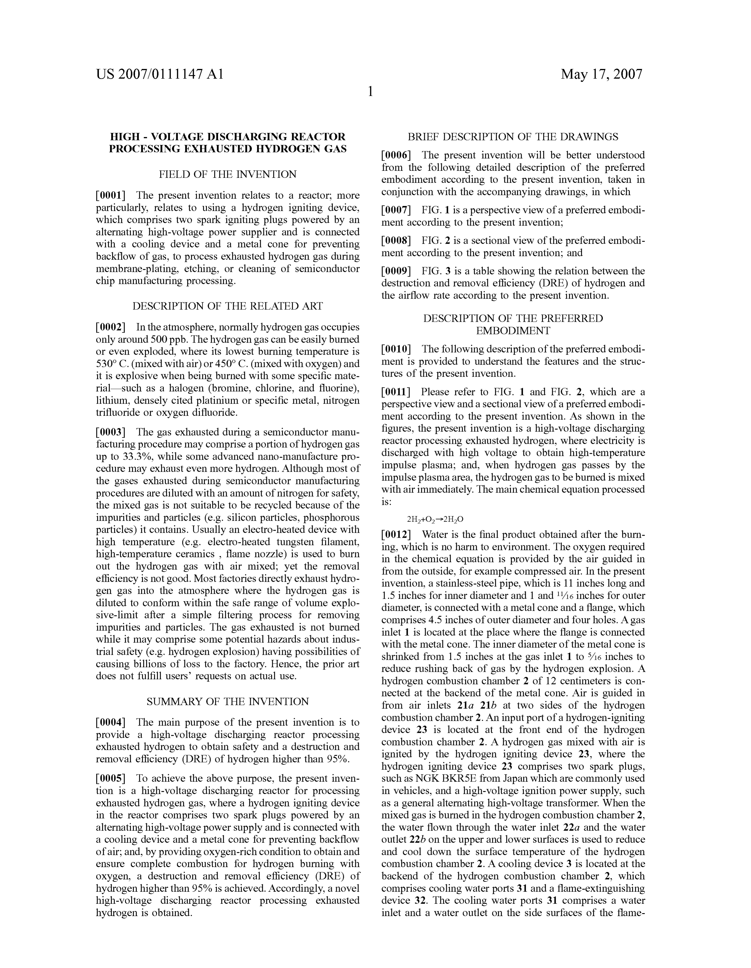
rial—such as a halogen (bromine, chlorine, and fluorine), 0011 Please refer to FIG. 1 and FIG. 2, which are a lithium, densely cited platinium or specific metal, nitrogen perspective view and a sectional view of a preferred embodi trifluoride or oxygen difluoride. ment according to the present invention. As shown in the 0003. The gas exhausted during a semiconductor manu figures, the present invention is a high-voltage discharging facturing procedure may comprise a portion of hydrogen gas reactor processing exhausted hydrogen, where electricity is up to 33.3%, while Some advanced nano-manufacture pro discharged with high Voltage to obtain high-temperature cedure may exhaust even more hydrogen. Although most of impulse plasma; and, when hydrogen gas passes by the the gases exhausted during semiconductor manufacturing impulse plasma area, the hydrogen gas to be burned is mixed procedures are diluted with an amount of nitrogen for safety, with air immediately. The main chemical equation processed
the mixed gas is not suitable to be recycled because of the impurities and particles (e.g. silicon particles, phosphorous particles) it contains. Usually an electro-heated device with 0012 Water is the final product obtained after the burn high temperature (e.g. electro-heated tungsten filament, ing, which is no harm to environment. The oxygen required high-temperature ceramics, flame nozzle) is used to burn in the chemical equation is provided by the air guided in out the hydrogen gas with air mixed; yet the removal from the outside, for example compressed air. In the present efficiency is not good. Most factories directly exhaust hydro invention, a stainless-steel pipe, which is 11 inches long and gen gas into the atmosphere where the hydrogen gas is 1.5 inches for inner diameter and 1 and 1/16 inches for outer diluted to conform within the safe range of volume explo diameter, is connected with a metal cone and a flange, which sive-limit after a simple filtering process for removing comprises 4.5 inches of outer diameter and four holes. Agas impurities and particles. The gas exhausted is not burned inlet 1 is located at the place where the flange is connected while it may comprise Some potential hazards about indus with the metal cone. The inner diameter of the metal cone is trial safety (e.g. hydrogen explosion) having possibilities of shrinked from 1.5 inches at the gas inlet 1 to 5/16 inches to causing billions of loss to the factory. Hence, the prior art reduce rushing back of gas by the hydrogen explosion. A does not fulfill users requests on actual use. hydrogen combustion chamber 2 of 12 centimeters is con
SUMMARY OF THE INVENTION
nected at the backend of the metal cone. Air is guided in from air inlets 21a 21b at two sides of the hydrogen 0004 The main purpose of the present invention is to combustion chamber 2. An input port of a hydrogen-igniting provide a high-voltage discharging reactor processing device 23 is located at the front end of the hydrogen exhausted hydrogen to obtain Safety and a destruction and combustion chamber 2. A hydrogen gas mixed with air is removal efficiency (DRE) of hydrogen higher than 95%. ignited by the hydrogen igniting device 23, where the hydrogen igniting device 23 comprises two spark plugs, 0005 To achieve the above purpose, the present inven such as NGK BKR5E from Japan which are commonly used tion is a high-voltage discharging reactor for processing in vehicles, and a high-voltage ignition power Supply, Such exhausted hydrogen gas, where a hydrogen igniting device as a general alternating high-voltage transformer. When the in the reactor comprises two spark plugs powered by an mixed gas is burned in the hydrogen combustion chamber 2, alternating high-voltage power Supply and is connected with the water flown through the water inlet 22a and the water a cooling device and a metal cone for preventing backflow outlet 22b on the upper and lower surfaces is used to reduce of air; and, by providing oxygen-rich condition to obtain and and cool down the Surface temperature of the hydrogen ensure complete combustion for hydrogen burning with combustion chamber 2. A cooling device 3 is located at the oxygen, a destruction and removal efficiency (DRE) of backend of the hydrogen combustion chamber 2, which hydrogen higher than 95% is achieved. Accordingly, a novel comprises cooling water ports 31 and a flame-extinguishing high-voltage discharging reactor processing exhausted device 32. The cooling water ports 31 comprises a water hydrogen is obtained. inlet and a water outlet on the side surfaces of the flame
Page 6
US 2007/011 1147 A1 May 17, 2007
extinguishing device 3. The fire-extinguishing device 32 What is claimed are:
comprises three overlapping sets of stainless Steel pipes with 1. A high-voltage discharging reactor designed for pro heat sink fins, which are also water cooled, to achieve the cessing exhausted hydrogen gas, comprising: requirement of no burning frame at the gas outlet 4 con An exhausted gas inlet;
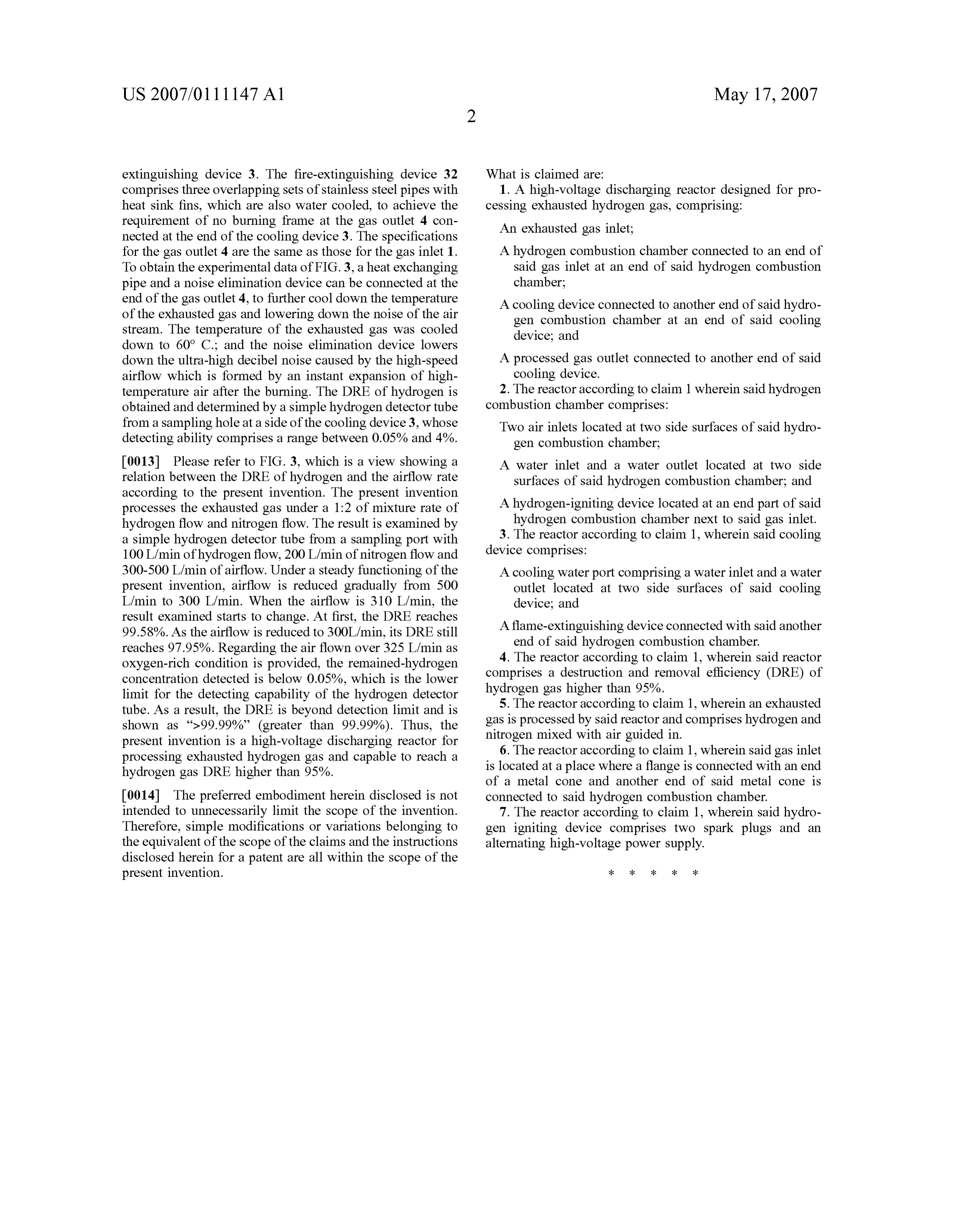
nected at the end of the cooling device 3. The specifications for the gas outlet 4 are the same as those for the gas inlet 1. A hydrogen combustion chamber connected to an end of To obtain the experimental data of FIG. 3, a heat exchanging said gas inlet at an end of said hydrogen combustion pipe and a noise elimination device can be connected at the chamber;
end of the gas outlet 4, to further cool down the temperature A cooling device connected to another end of said hydro of the exhausted gas and lowering down the noise of the air gen combustion chamber at an end of said cooling stream. The temperature of the exhausted gas was cooled device; and down to 60° C.; and the noise elimination device lowers down the ultra-high decibel noise caused by the high-speed A processed gas outlet connected to another end of said airflow which is formed by an instant expansion of high cooling device.
temperature air after the burning. The DRE of hydrogen is 2. The reactor according to claim 1 wherein said hydrogen obtained and determined by a simple hydrogen detector tube combustion chamber comprises:
from a sampling hole at a side of the cooling device 3, whose Two air inlets located at two side surfaces of said hydro detecting ability comprises a range between 0.05% and 4%. gen combustion chamber, 0013 Please refer to FIG. 3, which is a view showing a A water inlet and a water outlet located at two side relation between the DRE of hydrogen and the airflow rate Surfaces of said hydrogen combustion chamber; and according to the present invention. The present invention processes the exhausted gas under a 1:2 of mixture rate of A hydrogen-igniting device located at an end part of said hydrogen flow and nitrogen flow. The result is examined by hydrogen combustion chamber next to said gas inlet. a simple hydrogen detector tube from a sampling port with 3. The reactor according to claim 1, wherein said cooling 100 L/min of hydrogen flow, 200 L/min of nitrogen flow and device comprises:
300-500 L/min of airflow. Under a steady functioning of the A cooling water port comprising a water inlet and a water present invention, airflow is reduced gradually from 500 outlet located at two side Surfaces of said cooling L/min to 300 L/min. When the airflow is 310 L/min, the device; and result examined starts to change. At first, the DRE reaches A flame-extinguishing device connected with said another 99.58%. As the airflow is reduced to 300L/min, its DRE still reaches 97.95%. Regarding the air flown over 325 L/min as end of said hydrogen combustion chamber. oxygen-rich condition is provided, the remained-hydrogen 4. The reactor according to claim 1, wherein said reactor concentration detected is below 0.05%, which is the lower comprises a destruction and removal efficiency (DRE) of limit for the detecting capability of the hydrogen detector hydrogen gas higher than 95%.
tube. As a result, the DRE is beyond detection limit and is 5. The reactor according to claim 1, wherein an exhausted shown as ">99.99%” (greater than 99.99%). Thus, the gas is processed by said reactor and comprises hydrogen and present invention is a high-voltage discharging reactor for nitrogen mixed with air guided in. processing exhausted hydrogen gas and capable to reach a 6. The reactor according to claim 1, wherein said gas inlet hydrogen gas DRE higher than 95%. is located at a place where a flange is connected with an end of a metal cone and another end of said metal cone is 0014. The preferred embodiment herein disclosed is not connected to said hydrogen combustion chamber. intended to unnecessarily limit the scope of the invention. 7. The reactor according to claim 1, wherein said hydro Therefore, simple modifications or variations belonging to gen igniting device comprises two spark plugs and an the equivalent of the scope of the claims and the instructions alternating high-voltage power Supply. disclosed herein for a patent are all within the scope of the present invention. k k k k k
Provenance
- Collection
- Patents citing this work
- Original assignee
- Institute of Nuclear Energy Research
- Pages
- 6
- Method
- pdftotext (the PDF's own text layer) + pdftoppm 300dpi page scans
- Patent office record
- patents.google.com →
- Source
- Google Patents citing-documents table
- Inventors
- Chih-Ching Tzeng; Den-Lian Lin; Shiaw-Huei Chen; Ming-Song Yang; Jyh-Ming Yan; Yuh-Jeng Yu; Institute of Nuclear Energy Research
- Published
- 2007-05-17
- Transcribed from
- patentimages.storage.googleapis.com →