patent · US4738304
Direct condensation radiator for spacecraft
19 April 1988
Page 1 — bibliographic record
United States Patent (19) 11 Patent Number: 4,738,304 Chalmers et al. (45. Date of Patent: Apr. 19, 1988 54 DIRECT CONDENSATION RADATOR FOR 4,516,631 5/1985 Russell ................................. 165/47
SPACECRAFT
FOREIGN PATENT DOCUMENTS
75 Inventors: Douglas R. Chalmers; John J. Pustay, 23798 2/1982 Japan .................................. 165/11.1 both of Mercer County, N.J. 572889 10/1945 United Kingdom.................. 165/70 (73) Assignee: RCA Corporation, Princeton, N.J. 452718 12/1974 U.S.S.R. ................. ... 165/11.1 21 Appl. No.: 838,671 Primary Examiner-Albert W. Davis, Jr. Assistant Examiner-John K. Ford 22) Filed: Mar. 12, 1986 Attorney, Agent, or Firm-Clement A. Berard, Jr.; (51) Int, C.'....................... F28F 11/00; F28F 27/02; William H. Meise
(52) U.S. C. ..................................... 165/13; 165/11.1; 57 ABSTRACT 165/41; 165/70; 244/158 R; 244/163 Cost and weight of a heat transfer structure for a space (58) Field of Search .................... 165/41, 70, 13, 11.1; vehicle can be reduced by an arrangement of redundant 244/158 R, 163, 117 A channels for the flow of coolant to heat radiating panels, 56 References Cited micrometeroid resisting bumpers located adjacent the
energetic micrometeroids, and a sensing and control 3,211,215 10/1965 Walker .................................. 165/46 arrangement for sensing the penetration of a coolant 3,239,164 3/1966 Rapp ...... ... 244/117 A channel for shutting off that channel to prevent loss of 3,435,889 4/1969 Bienert ................................ 165/105 coolant.
3,517,730 6/1970 Wyatt.... ... 165/32 3,532,158 10/1970 Hiebert ...... ... 165/47 4,161,212 7/1979 Hightower ... ... 165/96 12 Claims, 15 Drawing Sheets
FURTHER RADATORS FURTHER RADATORS
SENSOR
PRESSURE
SENSOR
CONTROLLER
Page 2
Drawing sheet — no readable text.
Page 3
Drawing sheet — no readable text.
Page 4
Drawing sheet — no readable text.
Page 5
Drawing sheet — no readable text.
Page 6
Drawing sheet — no readable text.
Page 7
Drawing sheet — no readable text.
Page 8
Drawing sheet — no readable text.
Page 9
Drawing sheet — no readable text.
Page 10
Drawing sheet — no readable text.
Page 11
Drawing sheet — no readable text.
Page 12
Drawing sheet — no readable text.
Page 13
Drawing sheet — no readable text.
Page 14
Drawing sheet — no readable text.
Page 15
Drawing sheet — no readable text.
Page 16
Drawing sheet — no readable text.
Page 17
are formed from heat conductive material and have
DIRECT CONDENSATION RADATOR FOR surfaces which radiate heat. An elongated pipe-like SPACECRAFT structure in the form of a thermally conductive thick
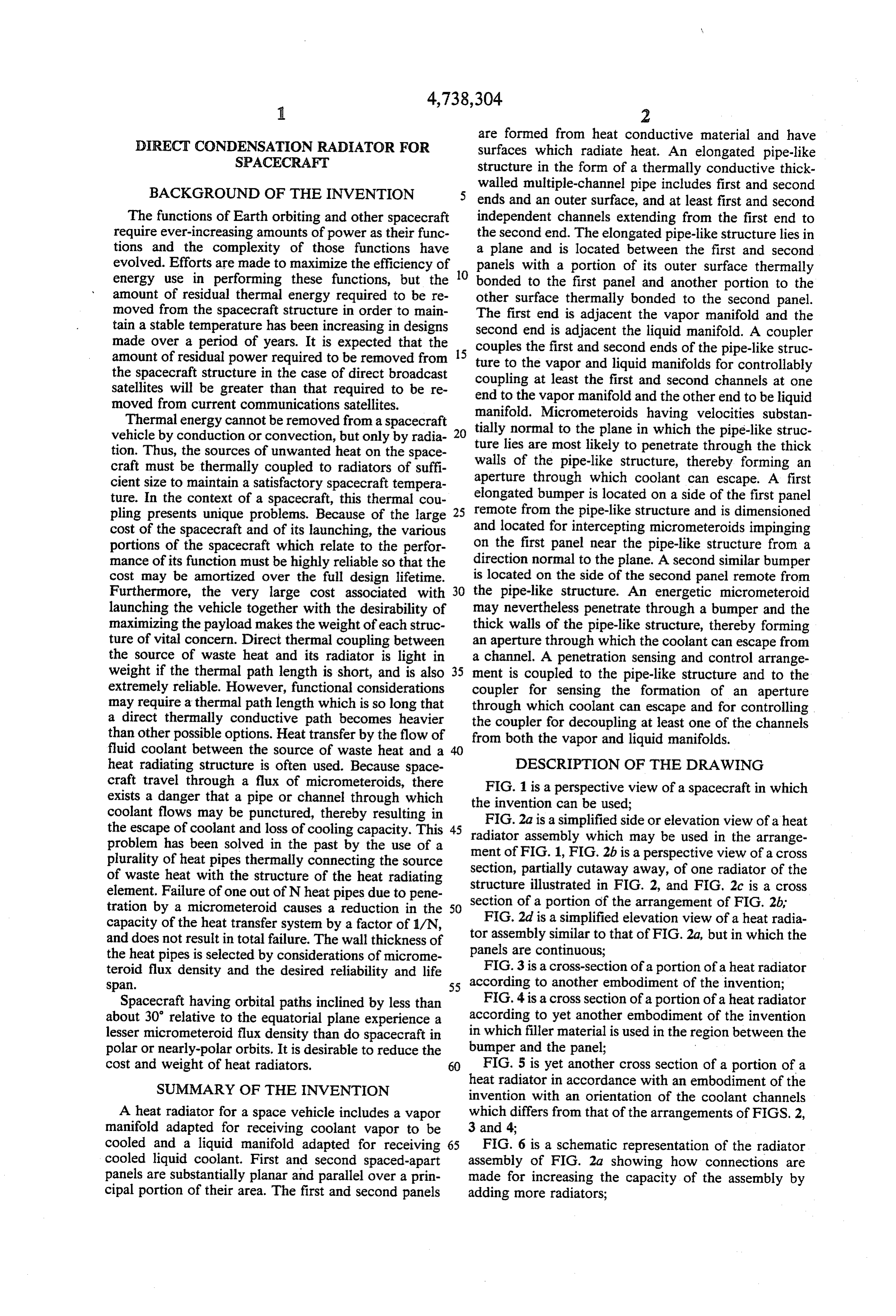
BACKGROUND OF THE INVENTION
walled multiple-channel pipe includes first and second 5 ends and an outer surface, and at least first and second
The functions of Earth orbiting and other spacecraft independent channels extending from the first end to require ever-increasing amounts of power as their func the second end. The elongated pipe-like structure lies in tions and the complexity of those functions have a plane and is located between the first and second evolved. Efforts are made to maximize the efficiency of 10 panels with a portion of its outer surface thermally energy use in performing these functions, but the bonded to the first panel and another portion to the amount of residual thermal energy required to be re other surface thermally bonded to the second panel. moved from the spacecraft structure in order to main The first end is adjacent the vapor manifold and the tain a stable temperature has been increasing in designs second end is adjacent the liquid manifold. A coupler made over a period of years. It is expected that the 15 couples the first and second ends of the pipe-like struc amount of residual power required to be removed from ture to the vapor and liquid manifolds for controllably the spacecraft structure in the case of direct broadcast coupling at least the first and second channels at one satellites will be greater than that required to be re end to the vapor manifold and the other end to be liquid moved from current communications satellites.
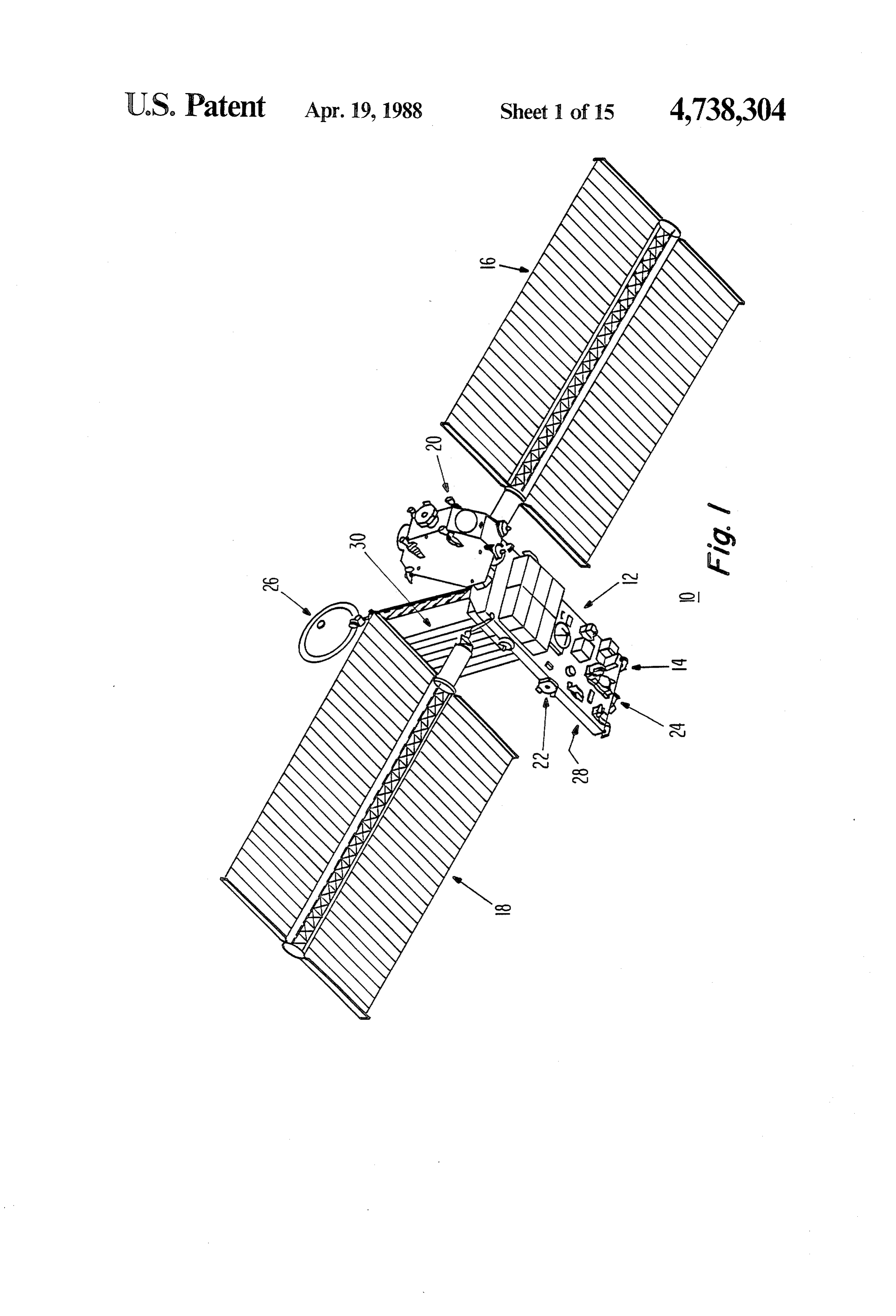
Thermal energy cannot be removed from a spacecraft manifold. Micrometeroids having velocities substan vehicle by conduction or convection, but only by radia 20 tially normal to the plane in which the pipe-like struc tion. Thus, the sources of unwanted heat on the space walls ofare ture lies most likely to penetrate through the thick the pipe-like structure, thereby forming an craft must be thermally coupled to radiators of suffi cient size to maintain a satisfactory spacecraft tempera aperture through which coolant can escape. A first ture. In the context of a spacecraft, this thermal cou elongated bumper is located on a side of the first panel pling presents unique problems. Because of the large 25 remote from the pipe-like structure and is dimensioned cost of the spacecraft and of its launching, the various and located for intercepting micrometeroids impinging portions of the spacecraft which relate to the perfor on the first panel near the pipe-like structure from a mance of its function must be highly reliable so that the direction normal to the plane. A second similar bumper cost may be amortized over the full design lifetime. is located on the side of the second panel remote from Furthermore, the very large cost associated with 30 the pipe-like structure. An energetic micrometeroid launching the vehicle together with the desirability of may nevertheless penetrate through a bumper and the maximizing the payload makes the weight of each struc thick walls of the pipe-like structure, thereby forming ture of vital concern. Direct thermal coupling between an aperture through which the coolant can escape from the source of waste heat and its radiator is light in a channel. A penetration sensing and control arrange weight if the thermal path length is short, and is also 35 ment is coupled to the pipe-like structure and to the extremely reliable. However, functional considerations coupler for sensing the formation of an aperture may require a thermal path length which is so long that through which coolant can escape and for controlling a direct thermally conductive path becomes heavier the coupler for decoupling at least one of the channels than other possible options. Heat transfer by the flow of from both the vapor and liquid manifolds. fluid coolant between the source of waste heat and a 40 heat radiating structure is often used. Because space DESCRIPTION OF THE DRAWING craft travel through a flux of micrometeroids, there exists a danger that a pipe or channel through which theFIG. 1 is a perspective view of a spacecraft in which invention can be used;
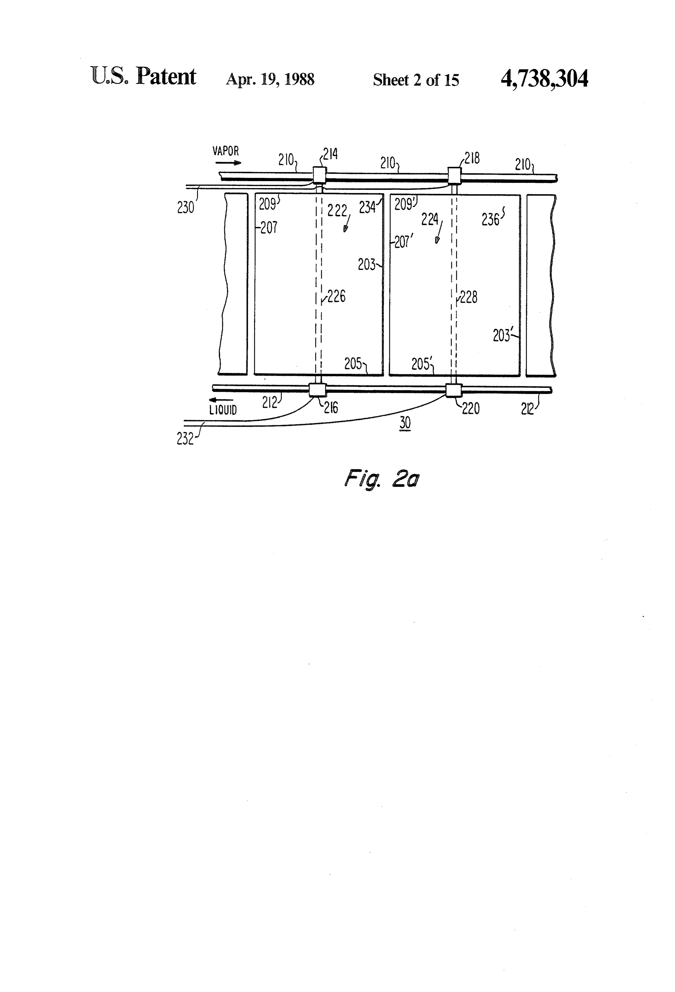
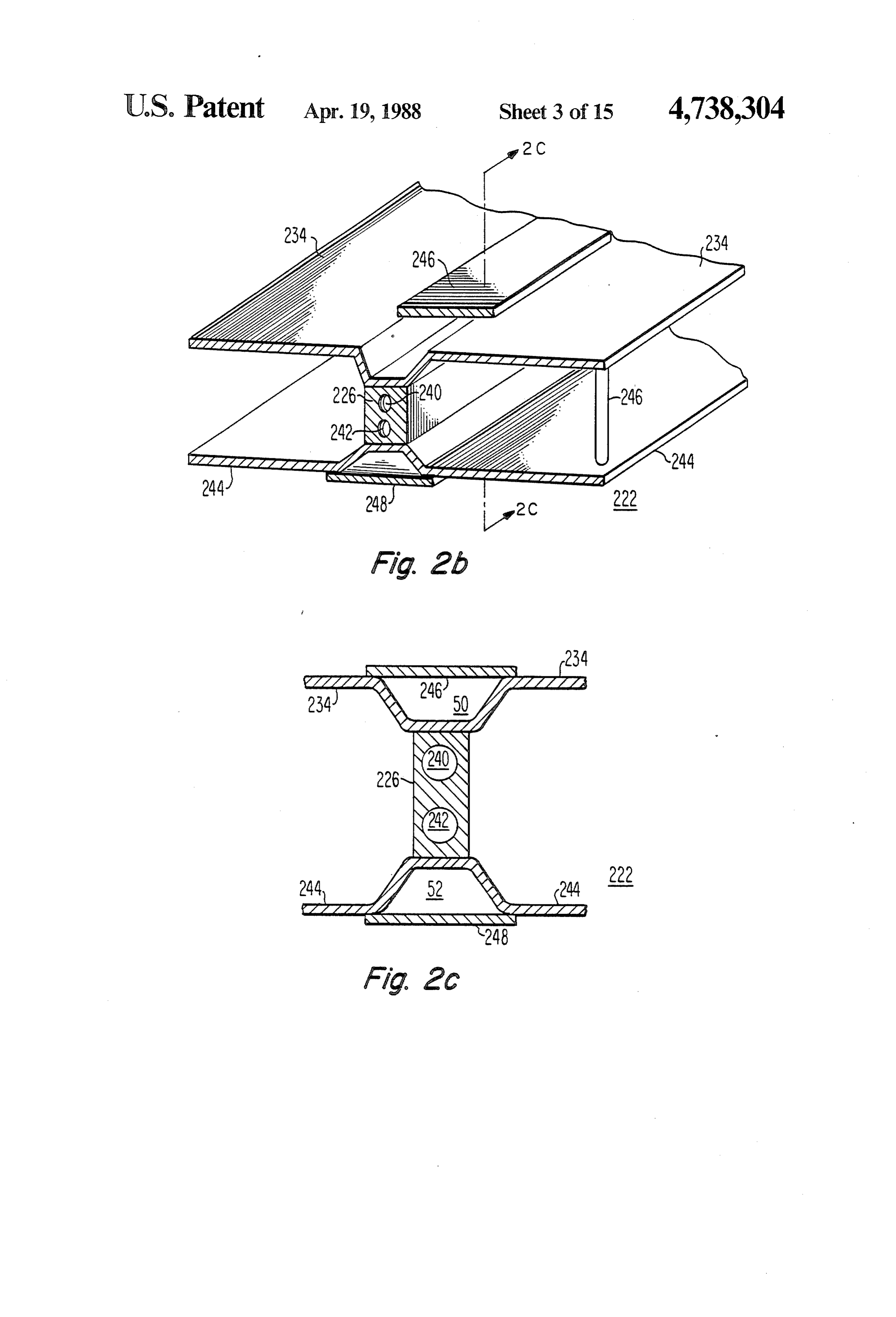
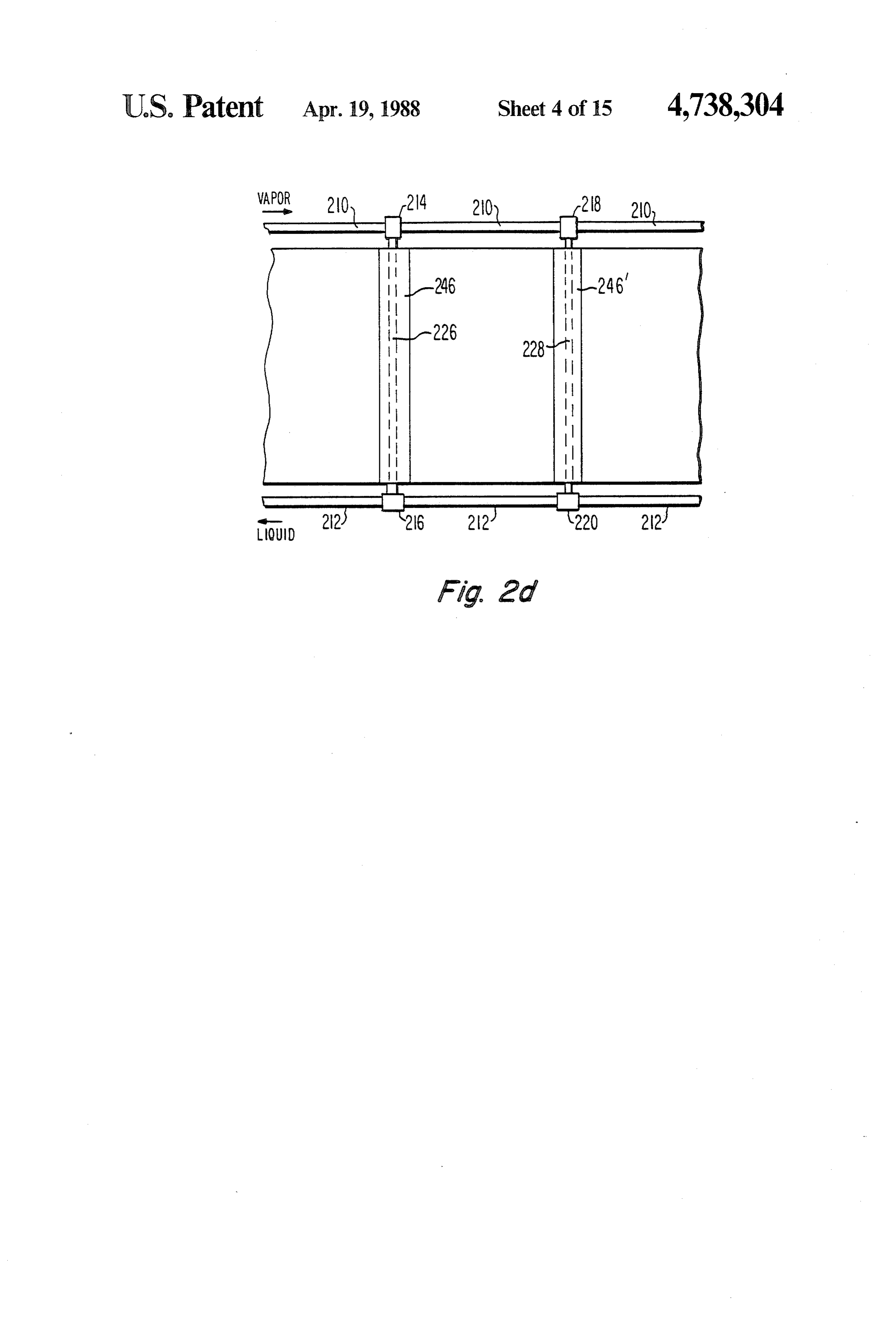
coolant flows may be punctured, thereby resulting in FIG.2a is a simplified side or elevation view of a heat the escape of coolant and loss of cooling capacity. This 45 radiator assembly which may be used in the arrange problem has been solved in the past by the use of a ment of FIG. 1, FIG.2b is a perspective view of a cross plurality of heat pipes thermally connecting the source section, partially cutaway away, of one radiator of the of waste heat with the structure of the heat radiating structure illustrated in FIG. 2, and FIG. 2c is a cross element. Failure of one out of N heat pipes due to pene section of a portion of the arrangement of FIG. 2b, tration by a micrometeroid causes a reduction in the 50 capacity of the heat transfer system by a factor of 1/N, FIG. 2d is a simplified elevation view of a heat radia and does not result in total failure. The wall thickness of tor assembly similar to that of FIG. 2a, but in which the the heat pipes is selected by considerations of microme panels are continuous;
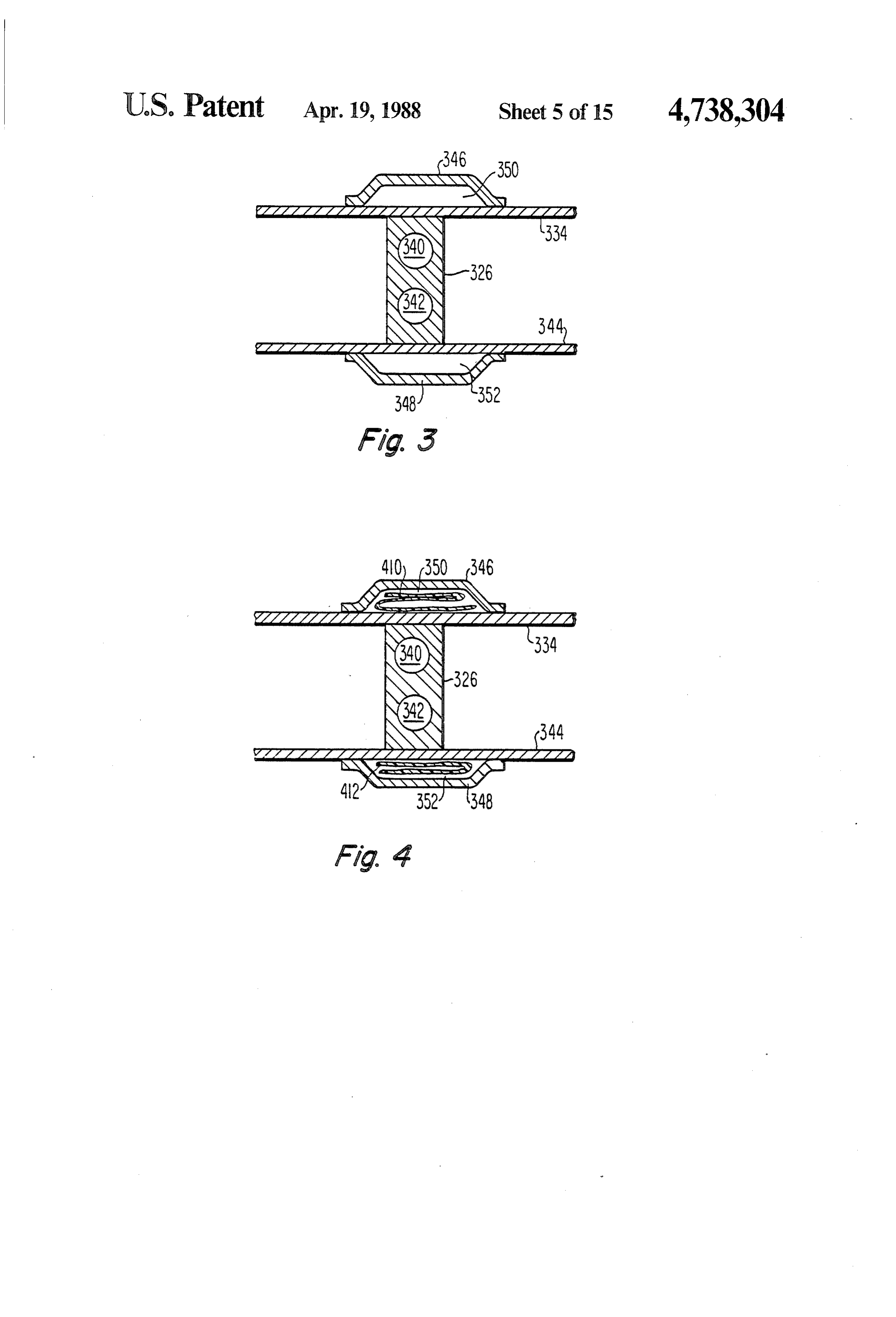
teroid flux density and the desired reliability and life FIG. 3 is a cross-section of a portion of a heat radiator span. 55 according to another embodiment of the invention; Spacecraft having orbital paths inclined by less than FIG. 4 is a cross section of a portion of a heat radiator about 30 relative to the equatorial plane experience a according to yet another embodiment of the invention lesser micrometeroid flux density than do spacecraft in in which filler material is used in the region between the polar or nearly-polar orbits. It is desirable to reduce the bumper and the panel;
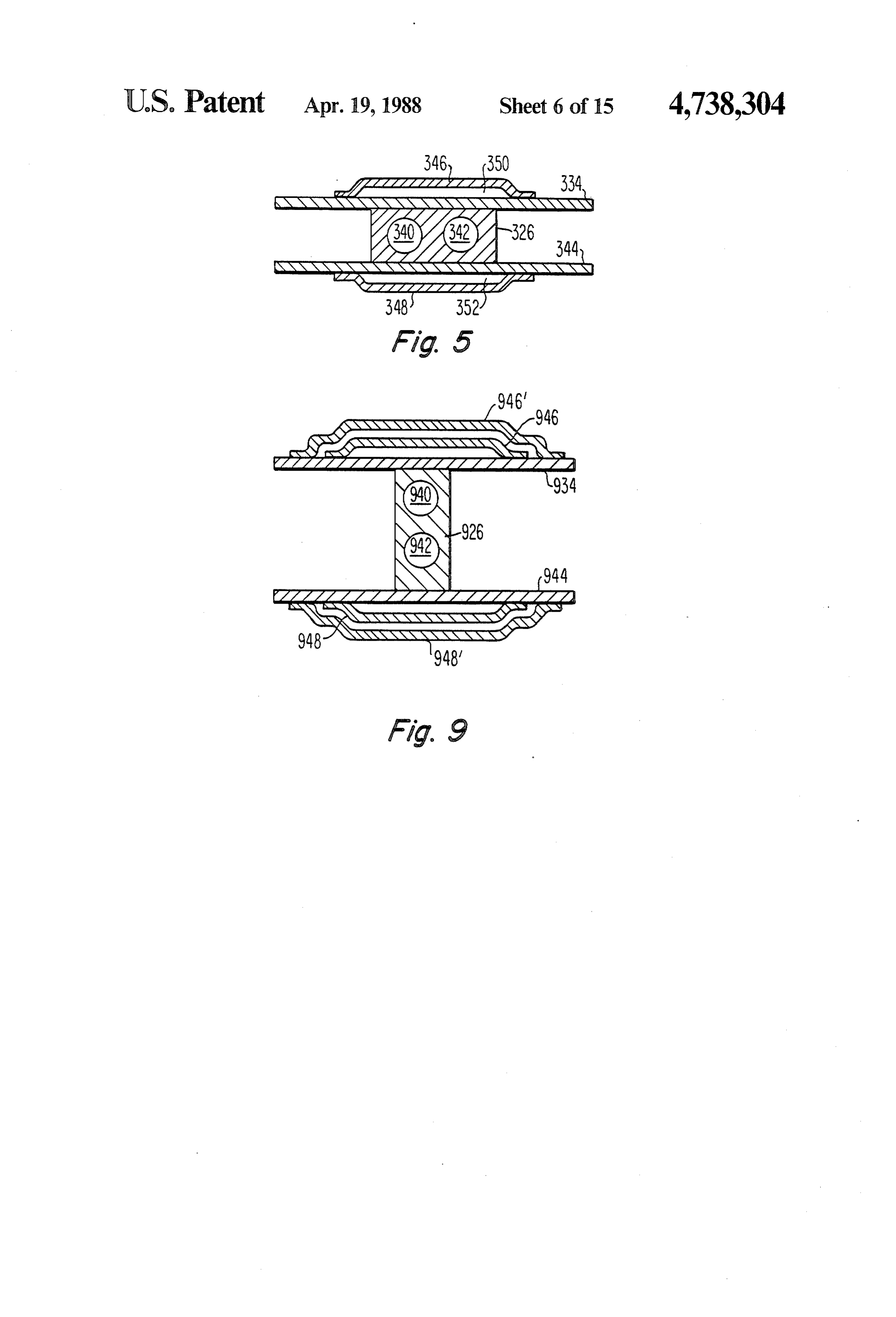
cost and weight of heat radiators. 60 FIG. 5 is yet another cross section of a portion of a heat radiator in accordance with an embodiment of the
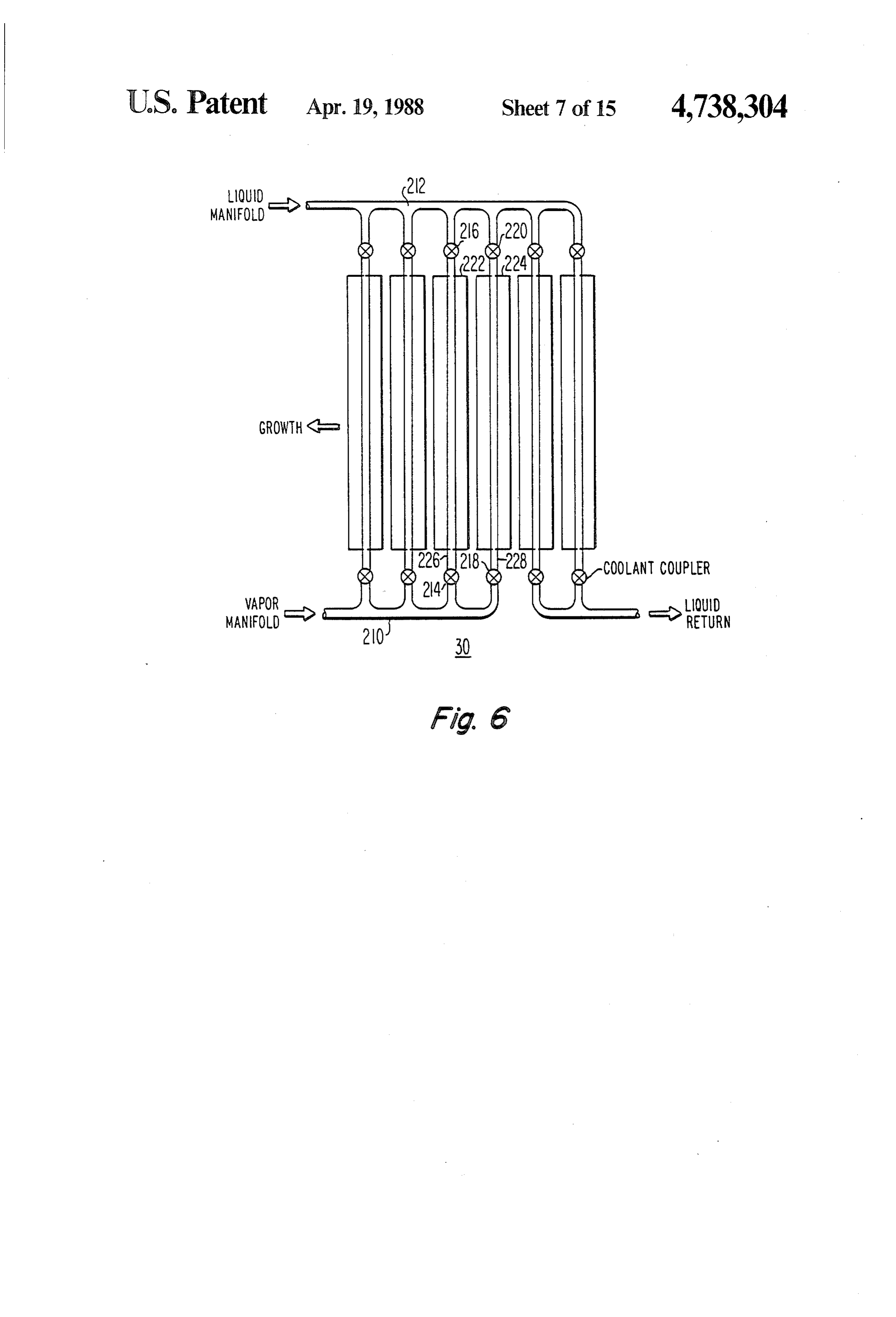
SUMMARY OF THE INVENTION invention with an orientation of the coolant channels A heat radiator for a space vehicle includes a vapor which differs from that of the arrangements of FIGS. 2, manifold adapted for receiving coolant vapor to be 3 and 4;
cooled and a liquid manifold adapted for receiving 65 FIG. 6 is a schematic representation of the radiator cooled liquid coolant. First and second spaced-apart assembly of FIG. 2a showing how connections are panels are substantially planar and parallel over a prin made for increasing the capacity of the assembly by cipal portion of their area. The first and second panels adding more radiators;
Page 18
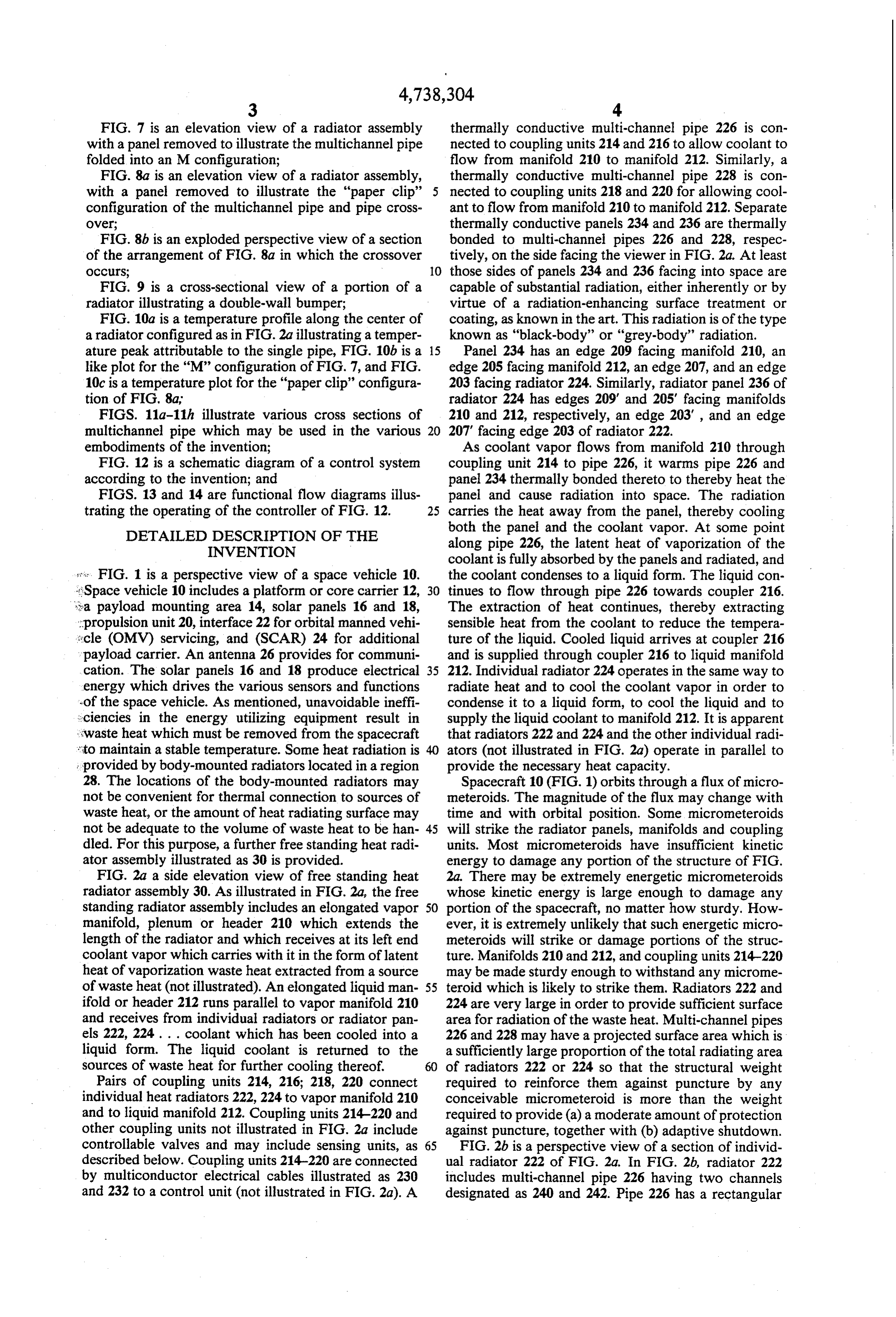
FIG. 7 is an elevation view of a radiator assembly thermally conductive multi-channel pipe 226 is con with a panel removed to illustrate the multichannel pipe nected to coupling units 214 and 216 to allow coolant to folded into an M configuration; flow from manifold 210 to manifold 212. Similarly, a FIG. 8a is an elevation view of a radiator assembly, thermally conductive multi-channel pipe 228 is con with a panel removed to illustrate the "paper clip' 5 nected to coupling units 218 and 220 for allowing cool configuration of the multichannel pipe and pipe cross ant to flow from manifold 210 to manifold 212. Separate over; thermally conductive panels 234 and 236 are thermally FIG. 8b is an exploded perspective view of a section bonded to multi-channel pipes 226 and 228, respec of the arrangement of FIG. 8a in which the crossover tively, on the side facing the viewer in FIG.2a. At least occurs; 10 those sides of panels 234 and 236 facing into space are FIG. 9 is a cross-sectional view of a portion of a capable of substantial radiation, either inherently or by radiator illustrating a double-wall bumper; virtue of a radiation-enhancing surface treatment or FIG. 10a is a temperature profile along the center of coating, as known in the art. This radiation is of the type a radiator configured as in FIG.2a illustrating a temper known as "black-body' or "grey-body' radiation. ature peak attributable to the single pipe, FIG. 10b is a 15 Panel 234 has an edge 209 facing manifold 210, an like plot for the “M” configuration of FIG. 7, and FIG. edge 205 facing manifold 212, an edge 207, and an edge 10c is a temperature plot for the "paper clip' configura 203 facing radiator 224. Similarly, radiator panel 236 of tion of FIG. 8a, radiator 224 has edges 209' and 205" facing manifolds FIGS. 11a-11h illustrate various cross sections of 210 and 212, respectively, an edge 203, and an edge multichannel pipe which may be used in the various 20 207" facing edge 203 of radiator 222. embodiments of the invention; As coolant vapor flows from manifold 210 through FIG. 12 is a schematic diagram of a control system coupling unit 214 to pipe 226, it warms pipe 226 and according to the invention; and panel 234 thermally bonded thereto to thereby heat the FIGS. 13 and 14 are functional flow diagrams illus panel and cause radiation into space. The radiation trating the operating of the controller of FIG. 12. 25 carries the heat away from the panel, thereby cooling DETAILED DESCRIPTION OF THE both the panel and the coolant vapor. At some point INVENTION along pipe 226, the latent heat of vaporization of the coolant is fully absorbed by the panels and radiated, and res. FIG. 1 is a perspective view of a space vehicle 10. the coolant condenses to a liquid form. The liquid con :Space vehicle 10 includes a platform or core carrier 12, 30 tinues to flow through pipe 226 towards coupler 216. &a payload mounting area 14, solar panels 16 and 18, The extraction of heat continues, thereby extracting propulsion unit 20, interface 22 for orbital manned vehi sensible heat from the coolant to reduce the tempera scle (OMV) servicing, and (SCAR) 24 for additional ture of the liquid. Cooled liquid arrives at coupler 216 payload carrier. An antenna 26 provides for communi and is supplied through coupler 216 to liquid manifold cation. The solar panels 16 and 18 produce electrical 35 212. Individual radiator 224 operates in the same way to energy which drives the various sensors and functions radiate heat and to cool the coolant vapor in order to -of the space vehicle. As mentioned, unavoidable ineffi condense it to a liquid form, to cool the liquid and to kciencies in the energy utilizing equipment result in supply the liquid coolant to manifold 212. It is apparent waste heat which must be removed from the spacecraft that radiators 222 and 224 and the other individual radi * to maintain a stable temperature. Some heat radiation is 40 ators (not illustrated in FIG. 2a) operate in parallel to provided by body-mounted radiators located in a region provide the necessary heat capacity. 28. The locations of the body-mounted radiators may Spacecraft 10 (FIG. 1) orbits through a flux of micro not be convenient for thermal connection to sources of meteroids. The magnitude of the flux may change with waste heat, or the amount of heat radiating surface may time and with orbital position. Some micrometeroids not be adequate to the volume of waste heat to be han- 45 will strike the radiator panels, manifolds and coupling dled. For this purpose, a further free standing heat radi units. Most micrometeroids have insufficient kinetic ator assembly illustrated as 30 is provided. energy to damage any portion of the structure of FIG. FIG. 2a a side elevation view of free standing heat 2a. There may be extremely energetic micrometeroids radiator assembly 30. As illustrated in FIG. 2a, the free whose kinetic energy is large enough to damage any standing radiator assembly includes an elongated vapor 50 portion of the spacecraft, no matter how sturdy. How manifold, plenum or header 210 which extends the ever, it is extremely unlikely that such energetic micro length of the radiator and which receives at its left end meteroids will strike or damage portions of the struc coolant vapor which carries with it in the form of latent ture. Manifolds 210 and 212, and coupling units 214-220 heat of vaporization waste heat extracted from a source may be made sturdy enough to withstand any microme of waste heat (not illustrated). An elongated liquid man 55 teroid which is likely to strike them. Radiators 222 and ifold or header 212 runs parallel to vapor manifold 210 224 are very large in order to provide sufficient surface and receives from individual radiators or radiator pan area for radiation of the waste heat. Multi-channel pipes els 222, 224. . . coolant which has been cooled into a 226 and 228 may have a projected surface area which is liquid form. The liquid coolant is returned to the a sufficiently large proportion of the total radiating area sources of waste heat for further cooling thereof. 60 of radiators 222 or 224 so that the structural weight Pairs of coupling units 214, 216; 218, 220 connect required to reinforce them against puncture by any individual heat radiators 222, 224 to vapor manifold 210 conceivable micrometeroid is more than the weight and to liquid manifold 212. Coupling units 214-220 and required to provide (a) a moderate amount of protection other coupling units not illustrated in FIG. 2a include against puncture, together with (b) adaptive shutdown. controllable valves and may include sensing units, as 65 FIG. 2b is a perspective view of a section of individ described below. Coupling units 214-220 are connected ual radiator 222 of FIG. 2a. In FIG. 2b, radiator 222 by multiconductor electrical cables illustrated as 230 includes multi-channel pipe 226 having two channels and 232 to a control unit (not illustrated in FIG. 2a). A designated as 240 and 242. Pipe 226 has a rectangular
Page 19
cross section. As illustrated, panel 234 is substantially divided into individual radiators having panel edges planar over most of its surface area, but is bent to form such as 203, 207, 203', 207" of FIG. 2a, but instead form a flat-bottomed U-shape in the region in which it one continuous radiator. This tends to increase the ri contacts the outer surface of pipe 226. Panel 234 is gidity of the structure and to provide a more even ther metallurgically or adhesively bonded to the top portion mal distribution.
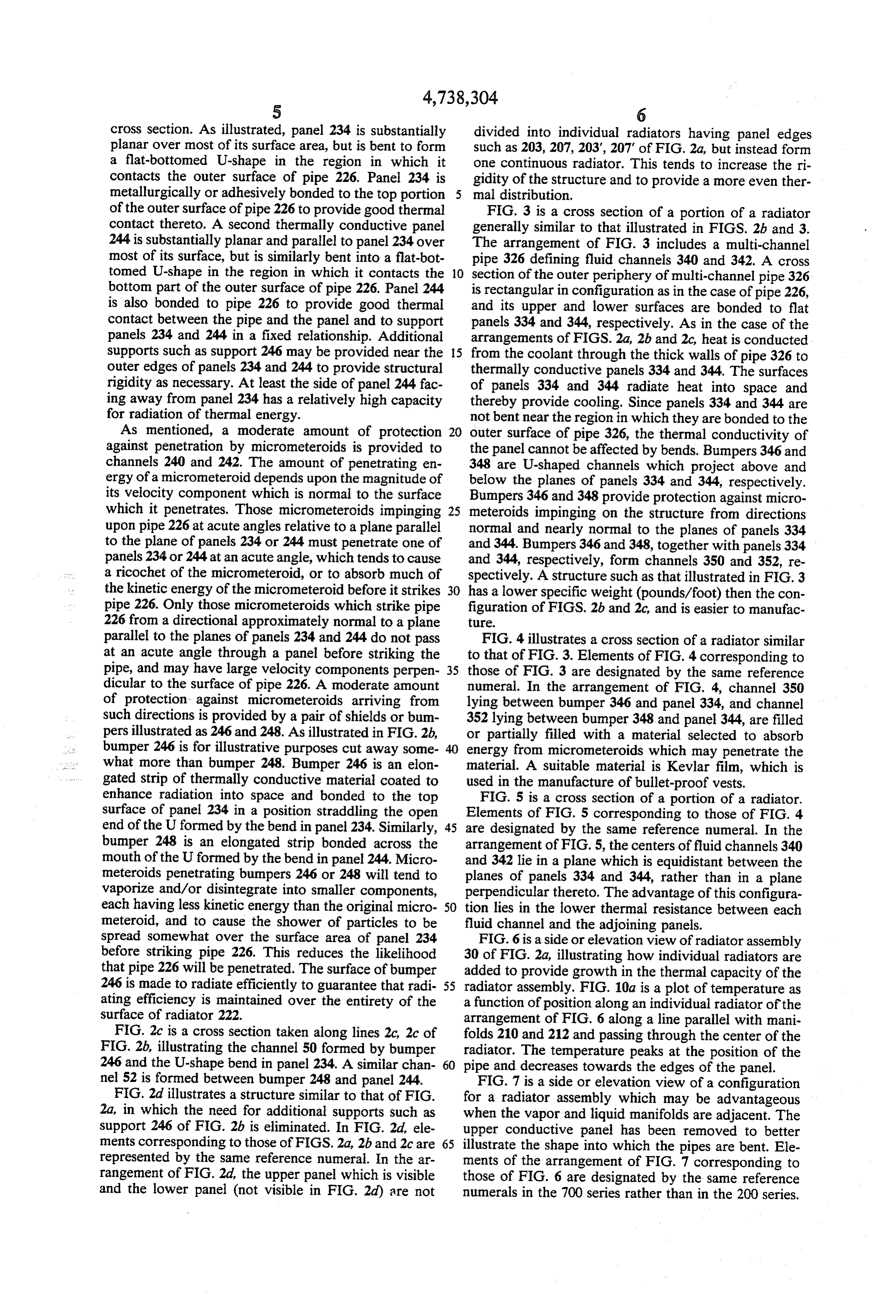
of the outer surface of pipe 226 to provide good thermal FIG. 3 is a cross section of a portion of a radiator contact thereto. A second thermally conductive panel generally similar to that illustrated in FIGS. 2b and 3. 244 is substantially planar and parallel to panel 234 over The arrangement of FIG. 3 includes a multi-channel most of its surface, but is similarly bent into a flat-bot pipe 326 defining fluid channels 340 and 342. A cross tomed U-shape in the region in which it contacts the 10 section of the outer periphery of multi-channel pipe 326 bottom part of the outer surface of pipe 226. Panel 244 is rectangular in configuration as in the case of pipe 226, is also bonded to pipe 226 to provide good thermal and its upper and lower surfaces are bonded to flat contact between the pipe and the panel and to support panels 334 and 344, respectively. As in the case of the panels 234 and 244 in a fixed relationship. Additional arrangements of FIGS. 2a, 2b and 2c, heat is conducted supports such as support 246 may be provided near the 15 from the coolant through the thick walls of pipe 326 to outer edges of panels 234 and 244 to provide structural thermally conductive panels 334 and 344. The surfaces rigidity as necessary. At least the side of panel 244 fac of panels 334 and 344 radiate heat into space and ing away from panel 234 has a relatively high capacity thereby provide cooling. Since panels 334 and 344 are for radiation of thermal energy. not bent near the region in which they are bonded to the As mentioned, a moderate amount of protection 20 outer surface of pipe 326, the thermal conductivity of against penetration by micrometeroids is provided to the panel cannot be affected by bends. Bumpers 346 and channels 240 and 242. The amount of penetrating en 348 are U-shaped channels which project above and ergy of a micrometeroid depends upon the magnitude of below the planes of panels 334 and 344, respectively. its velocity component which is normal to the surface Bumpers 346 and 348 provide protection against micro which it penetrates. Those micrometeroids impinging 25 meteroids impinging on the structure from directions upon pipe 226 at acute angles relative to a plane parallel normal and nearly normal to the planes of panels 334 to the plane of panels 234 or 244 must penetrate one of and 344. Bumpers 346 and 348, together with panels 334 panels 234 or 244 at an acute angle, which tends to cause and 344, respectively, form channels 350 and 352, re a ricochet of the micrometeroid, or to absorb much of spectively. A structure such as that illustrated in FIG. 3 the kinetic energy of the micrometeroid before it strikes 30 has a lower specific weight (pounds/foot) then the con pipe 226. Only those micrometeroids which strike pipe figuration of FIGS. 2b and 2c, and is easier to manufac 226 from a directional approximately normal to a plane ture.
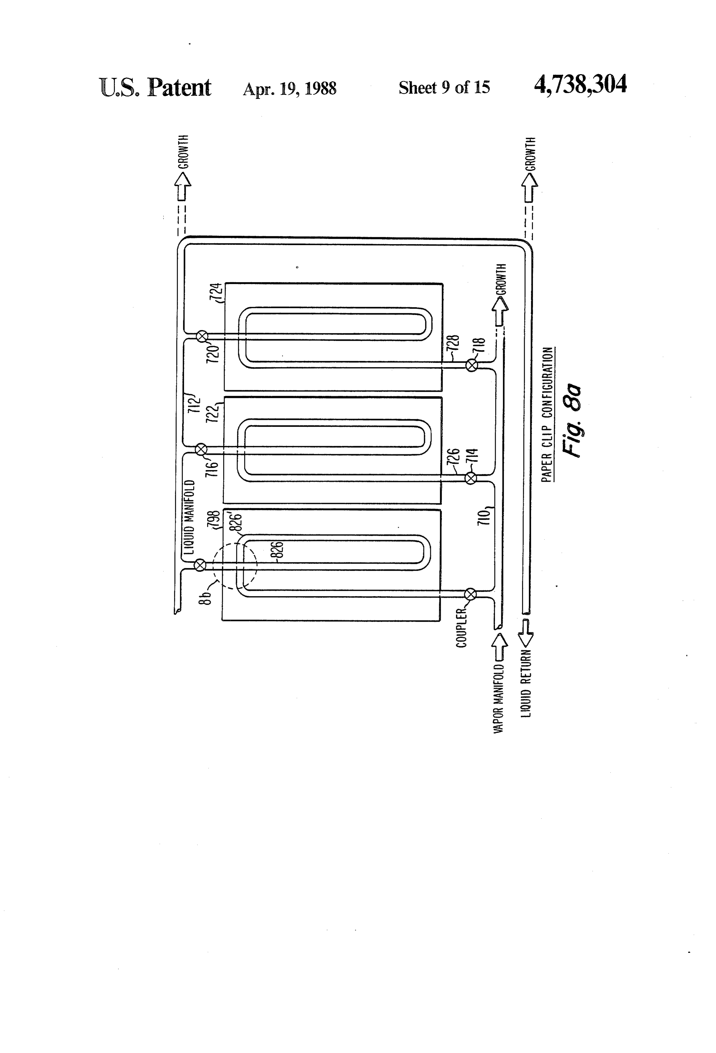
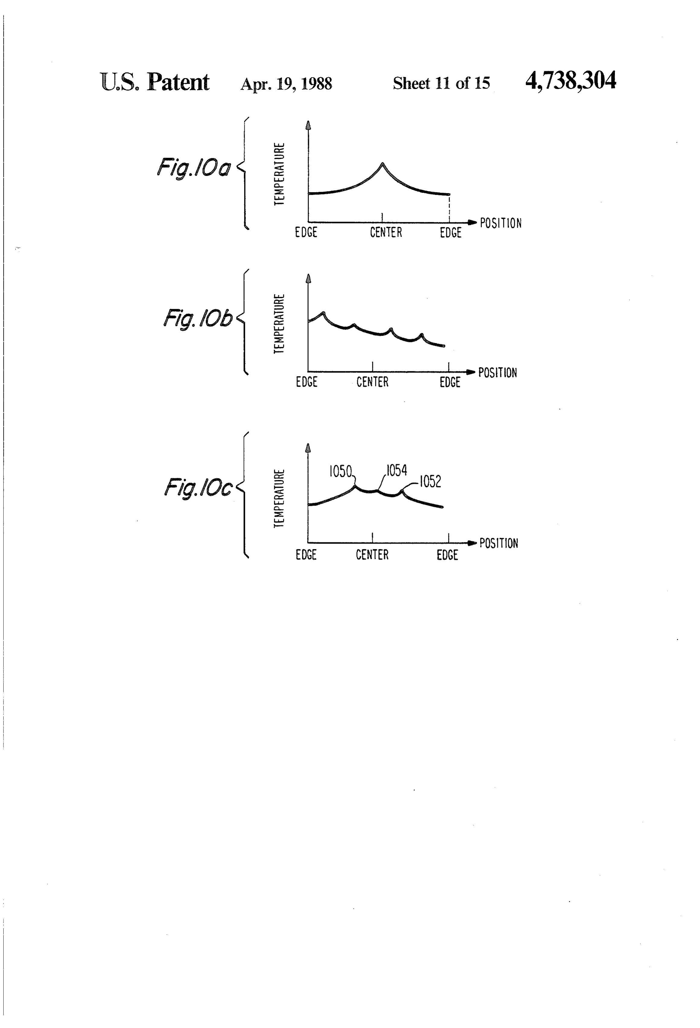
parallel to the planes of panels 234 and 244 do not pass FIG. 4 illustrates a cross section of a radiator similar at an acute angle through a panel before striking the to that of FIG. 3. Elements of FIG. 4 corresponding to pipe, and may have large velocity components perpen 35 those of FIG. 3 are designated by the same reference dicular to the surface of pipe 226. A moderate amount numeral. In the arrangement of FIG. 4, channel 350 of protection against micrometeroids arriving from lying between bumper 346 and panel 334, and channel such directions is provided by a pair of shields or bum 352 lying between bumper 348 and panel 344, are filled pers illustrated as 246 and 248. As illustrated in FIG.2b, or partially filled with a material selected to absorb bumper 246 is for illustrative purposes cut away some energy from micrometeroids which may penetrate the what more than bumper 248. Bumper 246 is an elon material. A suitable material is Kevlar film, which is gated strip of thermally conductive material coated to used in the manufacture of bullet-proof vests. enhance radiation into space and bonded to the top FIG. 5 is a cross section of a portion of a radiator. surface of panel 234 in a position straddling the open Elements of FIG. 5 corresponding to those of FIG. 4 end of the U formed by the bend in panel 234. Similarly, 45 are designated by the same reference numeral. In the bumper 248 is an elongated strip bonded across the arrangement of FIG. 5, the centers of fluid channels 340 mouth of the U formed by the bend in panel 244. Micro and 342 lie in a plane which is equidistant between the meteroids penetrating bumpers 246 or 248 will tend to planes of panels 334 and 344, rather than in a plane vaporize and/or disintegrate into smaller components, perpendicular thereto. The advantage of this configura each having less kinetic energy than the original micro 50 tion lies in the lower thermal resistance between each meteroid, and to cause the shower of particles to be fluid channel and the adjoining panels. spread somewhat over the surface area of panel 234 FIG. 6 is a side or elevation view of radiator assembly before striking pipe 226. This reduces the likelihood 30 of FIG. 2a, illustrating how individual radiators are that pipe 226 will be penetrated. The surface of bumper added to provide growth in the thermal capacity of the 246 is made to radiate efficiently to guarantee that radi 55 radiator assembly. FIG. 10a is a plot of temperature as ating efficiency is maintained over the entirety of the a function of position along an individual radiator of the surface of radiator 222. arrangement of FIG. 6 along a line parallel with mani FIG. 2c is a cross section taken along lines 2c, 2c of folds 210 and 212 and passing through the center of the FIG. 2b, illustrating the channel 50 formed by bumper radiator. The temperature peaks at the position of the 246 and the U-shape bend in panel 234. A similar chan 60 pipe and decreases towards the edges of the panel. nel 52 is formed between bumper 248 and panel 244. FIG. 7 is a side or elevation view of a configuration FIG. 2d illustrates a structure similar to that of FIG. for a radiator assembly which may be advantageous 2a, in which the need for additional supports such as when the vapor and liquid manifolds are adjacent. The support 246 of FIG. 2b is eliminated. In FIG. 2d, ele upper conductive panel has been removed to better ments corresponding to those of FIGS. 2a, 2b and 2c are 65 illustrate the shape into which the pipes are bent. Ele represented by the same reference numeral. In the ar ments of the arrangement of FIG. 7 corresponding to rangement of FIG. 2d, the upper panel which is visible those of FIG. 6 are designated by the same reference and the lower panel (not visible in FIG. 2d) are not numerals in the 700 series rather than in the 200 series.
Page 20
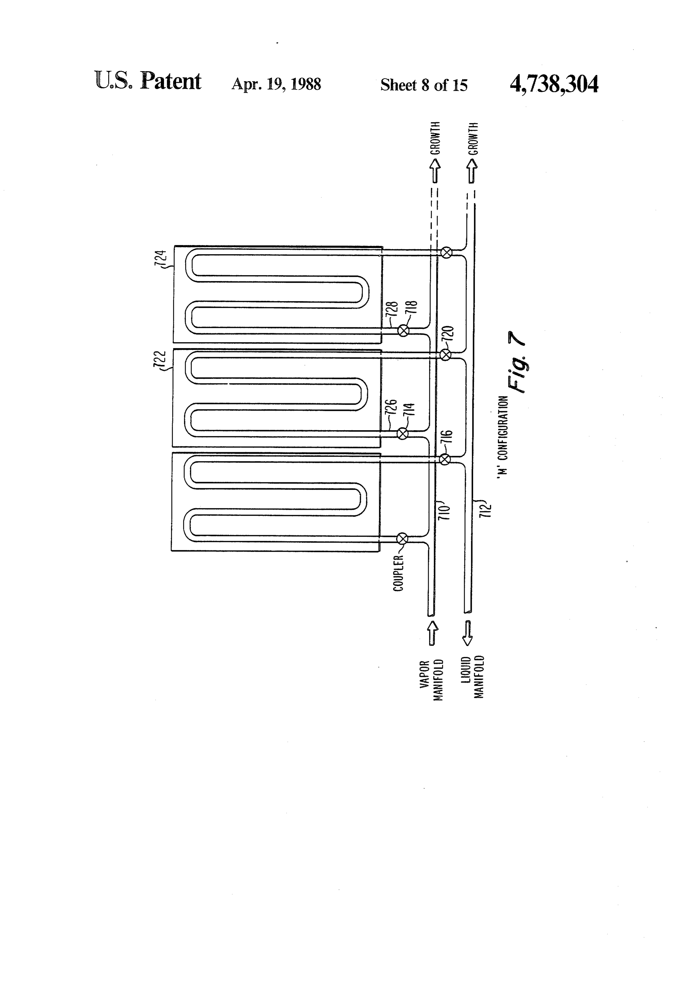
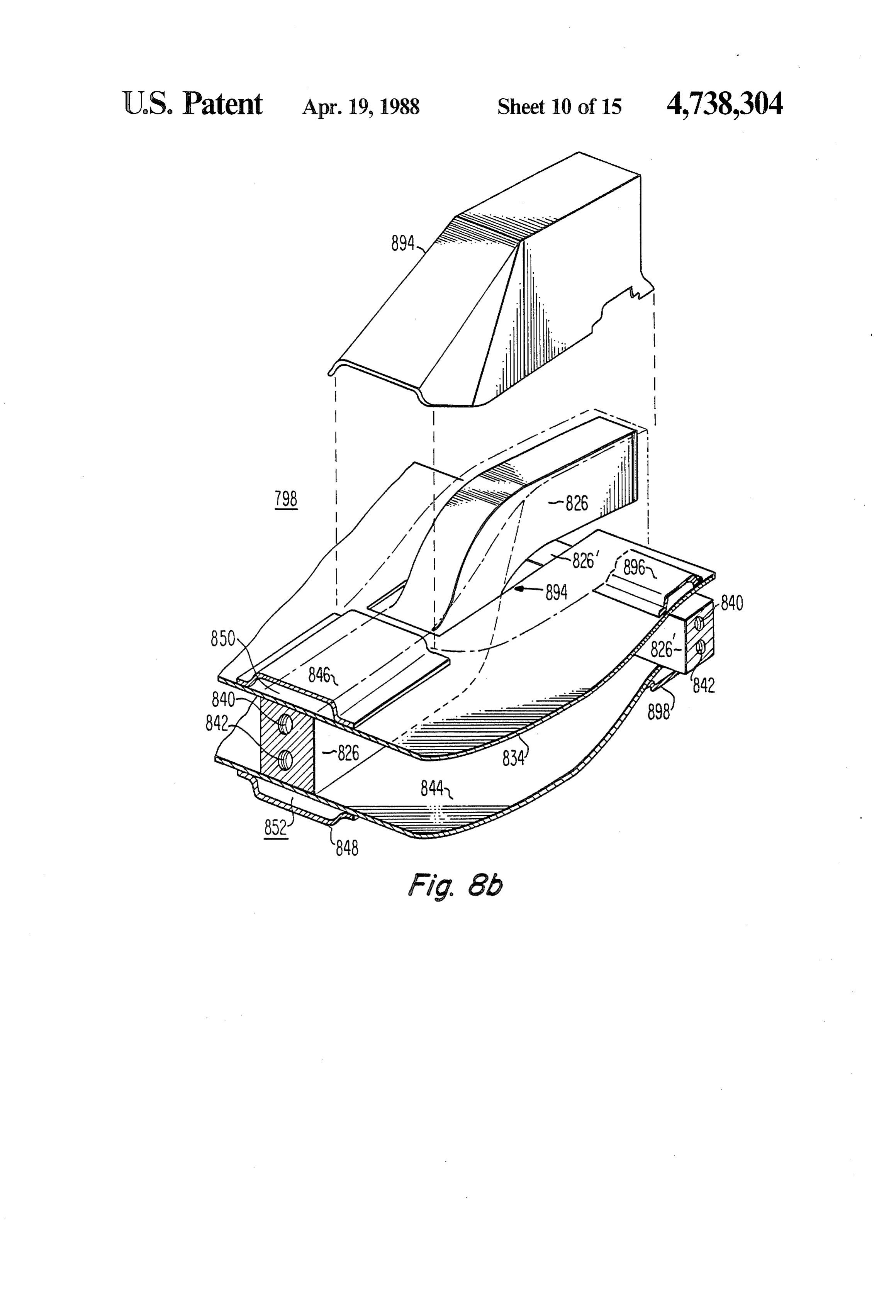
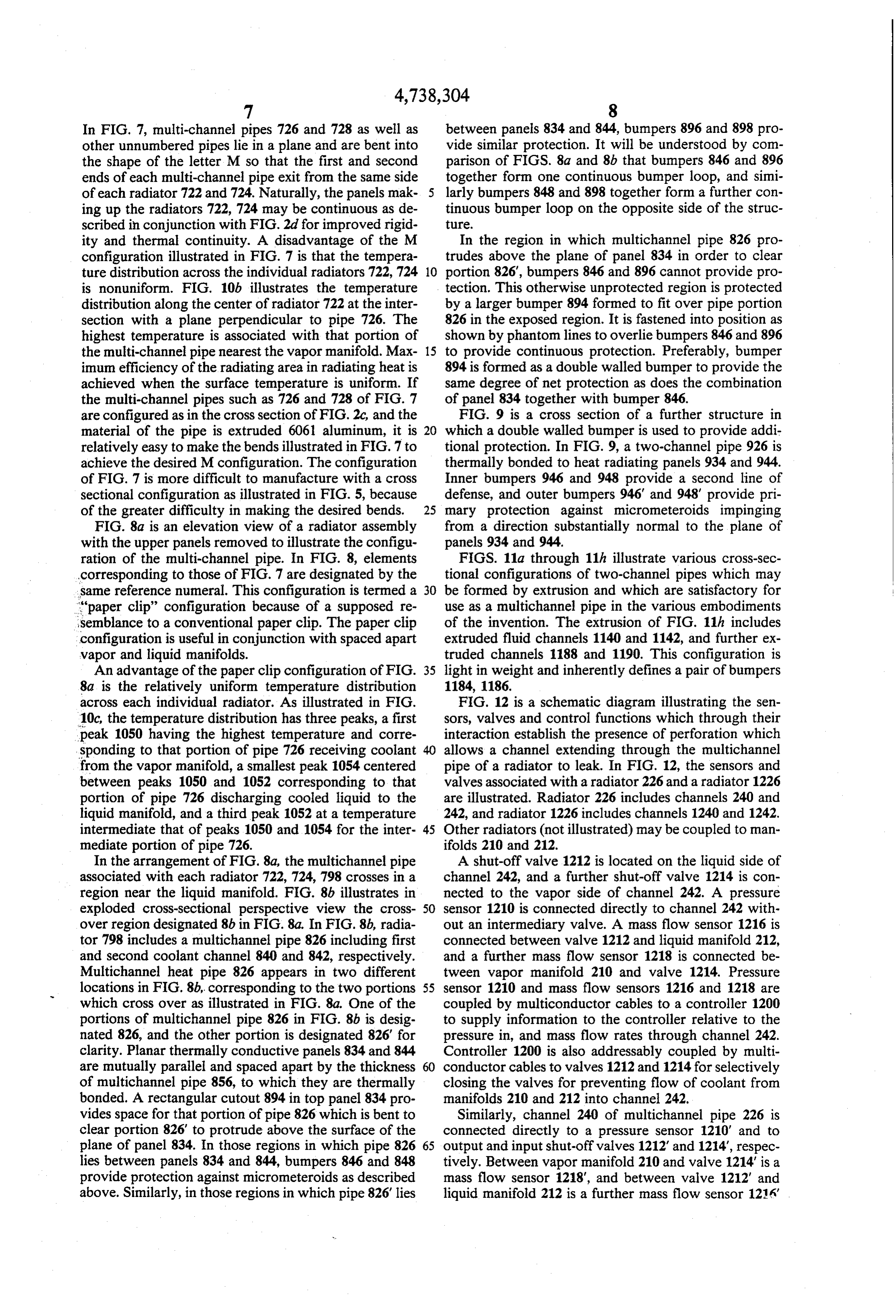
In FIG. 7, multi-channel pipes 726 and 728 as well as between panels 834 and 844, bumpers 896 and 898 pro other unnumbered pipes lie in a plane and are bent into vide similar protection. It will be understood by com the shape of the letter M so that the first and second parison of FIGS. 8a and 8b that bumpers 846 and 896 ends of each multi-channel pipe exit from the same side together form one continuous bumper loop, and simi of each radiator 722 and 724. Naturally, the panels mak 5 larly bumpers 848 and 898 together form a further con ing up the radiators 722, 724 may be continuous as de tinuous bumper loop on the opposite side of the struc scribed in conjunction with FIG. 2d for improved rigid ture.
ity and thermal continuity. A disadvantage of the M In the region in which multichannel pipe 826 pro configuration illustrated in FIG. 7 is that the tempera trudes above the plane of panel 834 in order to clear ture distribution across the individual radiators 722, 724 10 portion 826", bumpers 846 and 896 cannot provide pro is nonuniform. FIG. 10b illustrates the temperature tection. This otherwise unprotected region is protected distribution along the center of radiator 722 at the inter by a larger bumper 894 formed to fit over pipe portion section with a plane perpendicular to pipe 726. The 826 in the exposed region. It is fastened into position as highest temperature is associated with that portion of shown by phantom lines to overlie bumpers 846 and 896 the multi-channel pipe nearest the vapor manifold. Max 15 to provide continuous protection. Preferably, bumper imum efficiency of the radiating area in radiating heat is 894 is formed as a double walled bumper to provide the achieved when the surface temperature is uniform. If same degree of net protection as does the combination the multi-channel pipes such as 726 and 728 of FIG. 7 of panel 834 together with bumper 846. are configured as in the cross section of FIG.2c, and the FIG. 9 is a cross section of a further structure in material of the pipe is extruded 6061 aluminum, it is 20 which a double walled bumper is used to provide addi relatively easy to make the bends illustrated in FIG.7 to tional protection. In FIG. 9, a two-channel pipe 926 is achieve the desired M configuration. The configuration thermally bonded to heat radiating panels 934 and 944. of FIG. 7 is more difficult to manufacture with a cross Inner bumpers 946 and 948 provide a second line of sectional configuration as illustrated in FIG. 5, because defense, and outer bumpers 946 and 948' provide pri of the greater difficulty in making the desired bends. 25 mary protection against micrometeroids impinging FIG. 8a is an elevation view of a radiator assembly from a direction substantially normal to the plane of with the upper panels removed to illustrate the configu panels 934 and 944.
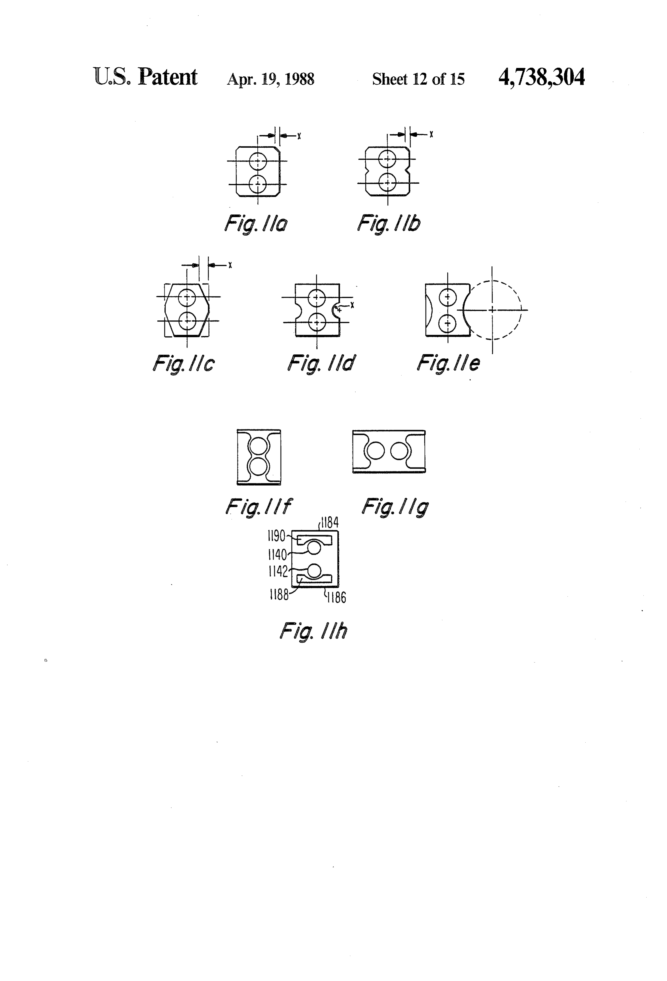
ration of the multi-channel pipe. In FIG. 8, elements FIGS. 11a through 11h illustrate various cross-sec corresponding to those of FIG. 7 are designated by the tional configurations of two-channel pipes which may same reference numeral. This configuration is termed a 30 be formed by extrusion and which are satisfactory for "paper clip" configuration because of a supposed re use as a multichannel pipe in the various embodiments semblance to a conventional paper clip. The paper clip of the invention. The extrusion of FIG. 11h includes configuration is useful in conjunction with spaced apart extruded fluid channels 1140 and 1142, and further ex vapor and liquid manifolds. truded channels 1188 and 1190. This configuration is An advantage of the paper clip configuration of FIG. 35 light in weight and inherently defines a pair of bumpers 8a is the relatively uniform temperature distribution 1184, 1186.
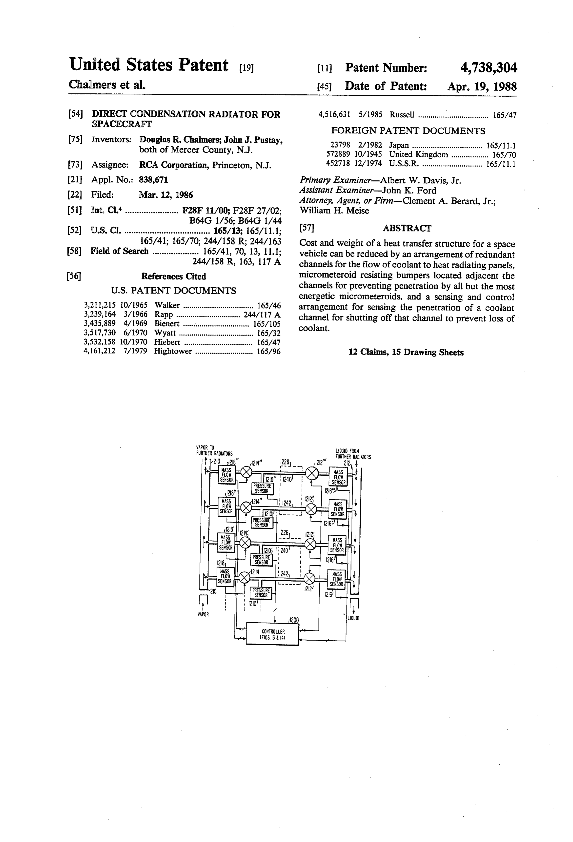
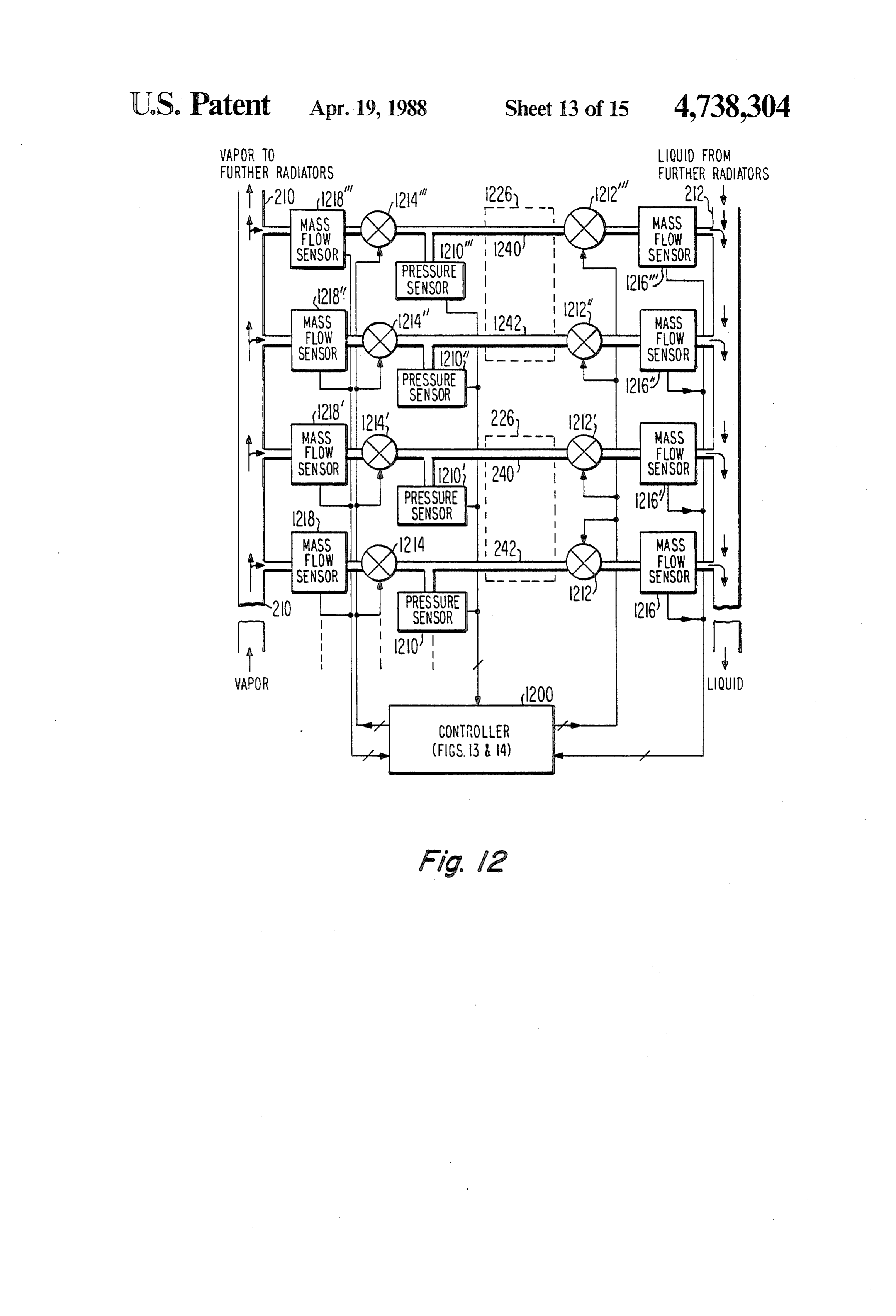
across each individual radiator. As illustrated in FIG. FIG. 12 is a schematic diagram illustrating the sen 10c, the temperature distribution has three peaks, a first sors, valves and control functions which through their peak 1050 having the highest temperature and corre interaction establish the presence of perforation which sponding to that portion of pipe 726 receiving coolant allows a channel extending through the multichannel from the vapor manifold, a smallest peak 1054 centered pipe of a radiator to leak. In FIG. 12, the sensors and between peaks 1050 and 1052 corresponding to that valves associated with a radiator 226 and a radiator 1226 portion of pipe 726 discharging cooled liquid to the are illustrated. Radiator 226 includes channels 240 and liquid manifold, and a third peak 1052 at a temperature 242, and radiator 1226 includes channels 1240 and 1242. intermediate that of peaks 1050 and 1054 for the inter 45 Other radiators (not illustrated) may be coupled to man mediate portion of pipe 726. ifolds 210 and 212.
In the arrangement of FIG. 8a, the multichannel pipe A shut-off valve 1212 is located on the liquid side of associated with each radiator 722, 724, 798 crosses in a channel 242, and a further shut-off valve 1214 is con region near the liquid manifold. FIG. 8b illustrates in nected to the vapor side of channel 242. A pressure exploded cross-sectional perspective view the cross 50 sensor 1210 is connected directly to channel 242 with over region designated 8b in FIG. 8a. In FIG. 8b, radia out an intermediary valve. A mass flow sensor 1216 is tor 798 includes a multichannel pipe 826 including first connected between valve 1212 and liquid manifold 212, and second coolant channel 840 and 842, respectively. and a further mass flow sensor 1218 is connected be Multichannel heat pipe 826 appears in two different tween vapor manifold 210 and valve 1214. Pressure locations in FIG. 8b, corresponding to the two portions 55 sensor 1210 and mass flow sensors 1216 and 1218 are which cross over as illustrated in FIG. 8a. One of the coupled by multiconductor cables to a controller 1200 portions of multichannel pipe 826 in FIG. 8b is desig to supply information to the controller relative to the nated 826, and the other portion is designated 826 for pressure in, and mass flow rates through channel 242. clarity. Planar thermally conductive panels 834 and 844 Controller 1200 is also addressably coupled by multi are mutually parallel and spaced apart by the thickness conductor cables to valves 1212 and 1214 for selectively of multichannel pipe 856, to which they are thermally closing the valves for preventing flow of coolant from bonded. A rectangular cutout 894 in top panel 834 pro manifolds 210 and 212 into channel 242. vides space for that portion of pipe 826 which is bent to Similarly, channel 240 of multichannel pipe 226 is clear portion 826 to protrude above the surface of the connected directly to a pressure sensor 1210' and to plane of panel 834. In those regions in which pipe 826 65 output and input shut-off valves 1212 and 1214", respec lies between panels 834 and 844, bumpers 846 and 848 tively. Between vapor manifold 210 and valve 1214 is a provide protection against micrometeroids as described mass flow sensor 1218", and between valve 1212" and above. Similarly, in those regions in which pipe 826 lies liquid manifold 212 is a further mass flow sensor 1216
Page 21
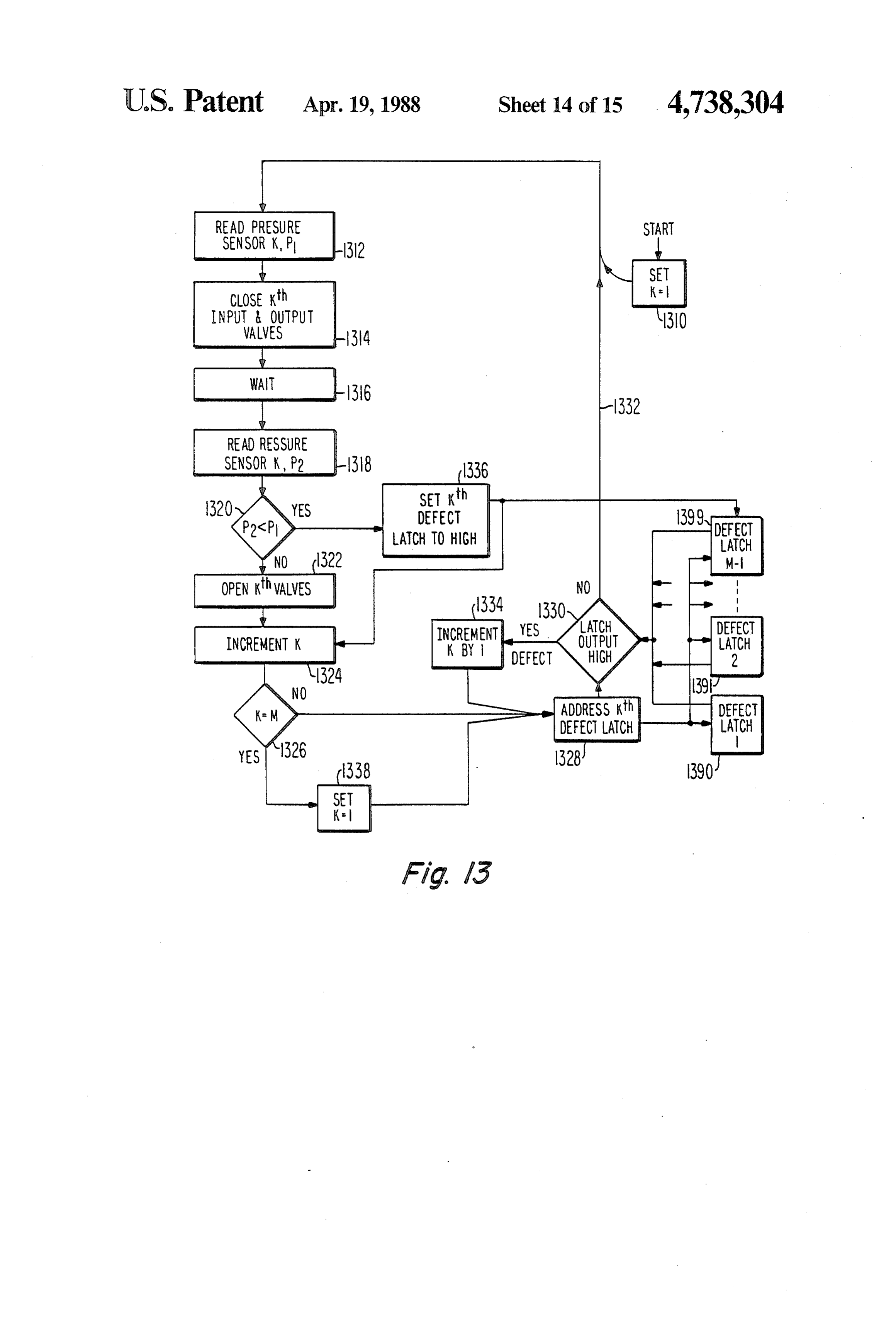
Similarly, channel 1242 of multichannel pipe 1226 is addressing of the Kth latch from among a plurality of connected in series with mass flow sensor 1218'', valve defect latches 1390, 1391, ... 1399. The current output 1214", a further valve 1212' and a further mass flow of the Kth defect latch can be a logic high or a logic sensor 1216", and is connected directly to a pressure low. A logic low output from the defect latch indicates sensor 1210'. Further channel 1240 of multichannel that the corresponding channel has not previously been pipe 1226 is connected to mass flow sensor 1218", valve found to be defective, whereas a logic high condition 1214", valve 1212', and mass flow sensor 1216', and is indicates that the corresponding channel has been found directly connected to pressure sensor 1210". Each of to be defective during a previous test. Since it is undesir the sensors can be individually read and each valve able to attempt further tests on a leaky channel because individual actuated under control of controller 1200. O of the potential for loss of coolant during the test, those Pressure sensors, mass sensors and valves are well values of K for which a corresponding defect latch has known in the art and need no further description. a logic high output level are bypassed and are not FIG. 13 is a functional logic flow diagram describing tested. This is accomplished by a decision block 1330 the sequence of operations of controller 1200 in sequen which determines whether the output of the defect tially testing each fluid channel of each multichannel 15 latch addressed by block 1328 is high or low. If the pipe for small leaks. In general, the method for testing latch output is low, the NO output of decision block for small leaks starts with all the valves open, and cool 1330 directs the logic by a path 1332 back to block 1312 ant flow through the channel to be tested. For example, to begin testing of the next channel (K=2) in the se in order to test channel 242 for small leaks, valves 1212 quence. On the other hand, if the defect latch addressed and 1214 are open for the flow of coolant therethrough. 20 by logic block 1328 has a logic high output level, deci Pressure sensor 1210 is read, and valves 1212 and 1214 sion block 1330 indicates by the YES output that this are then closed, thereby trapping coolant therein. If value of K should not be used, and the logic flows to a there is a small leak, the pressure will drop as a function block 1334 which increments K by one and the logic of time. Depending upon the amount of liquid in the returns to block 1328. In block 1328, the new value of K channel at the time the test begins, different periods may 25 (K=3) is used to address the third defect latch. If its be required to sense a drop in pressure. After a period of output is logic low (representing a fluid channel which time, pressure sensor 1210 is again read, and the differ has not previously been found to be defective), decision ence in the..readings is taken. If there is a change, this block 1330 allows the new value of K to be coupled to indicates that there is a small leak, and the logic is reset block 1312 to continue the sequence of tests. to maintain valves 1212 and 1214 closed permanently. If 30 Thus, channels known to be defective are not tested the pressure readings are the same, this indicates that for small leaks. During the first test of a channel follow the system is intact, and valves 1212 and 1214 are then ing a small puncture by a micrometeroid, the associated opened to allow coolant flow while the controller goes Kth pressure sensor (for example, 1210' of FIG. 12) is onto test another channel. It should be noted that the measured in block 1312 and the pressure reading P1 is testing for fine leaks does not require the use of mass 35 stored. The associated valves 1212", 1214 are closed in flow sensors. The mass flow sensors are monitored block 1314, and a waiting period ensues pursuant to continuously and in parallel in order to sense a sudden block 1316. The second reading of pressure sensor major rupture which might cause total loss of system 1210' will result in value P2 which is less than P1. coolant before the controller test sequence for small Consequently, decision logic 1320 will produce a YES leaks could get around to testing the ruptured channel. output which directs the logic to a block 1336 which FIG. 13 is a functional logic diagram illustrating the sets the Kth defect latch to a logic high level, and re sequence of operation for the testing of small leaks. The turns the logic to block 1324 for an incrementing of the system is started and a running variable K is set equal to value of K. Eventually, all the channels will have been 1 in a block 1310. The logic flows to a block 1312 which tested, and the value of K as incremented by block 1324 represents the reading of the Kth pressure sensor, which 45 will equal M. At that time, decision block 1326 indicates for K= 1 is pressure sensor 1210 of FIG. 12. A pressure by the YES output that the value of K should be reset reading P1 is stored. The logic flows to a block 1314 to unity, and directs the logic to a block 1338 in which which represents the closing of the Kth input and out K is set equal to one. From block 1338, the logic flows put valves, corresponding for K= 1 to valves 1212 and to block 1328 which addresses the first defect latch to 1214. The logic then flows to block 1316 which repre 50 determine if the first channel has previously been deter sents a wait or delay for a predetermined period of time mined to be defective, as described above. This se selected to detect leaks of the appropriate magnitude. quence of operation continues until failure of the space After the predetermined period, the logic flows to a vehicle, whether through cooling system failure or for block 1318 which represents the reading of the Kh other reasons.
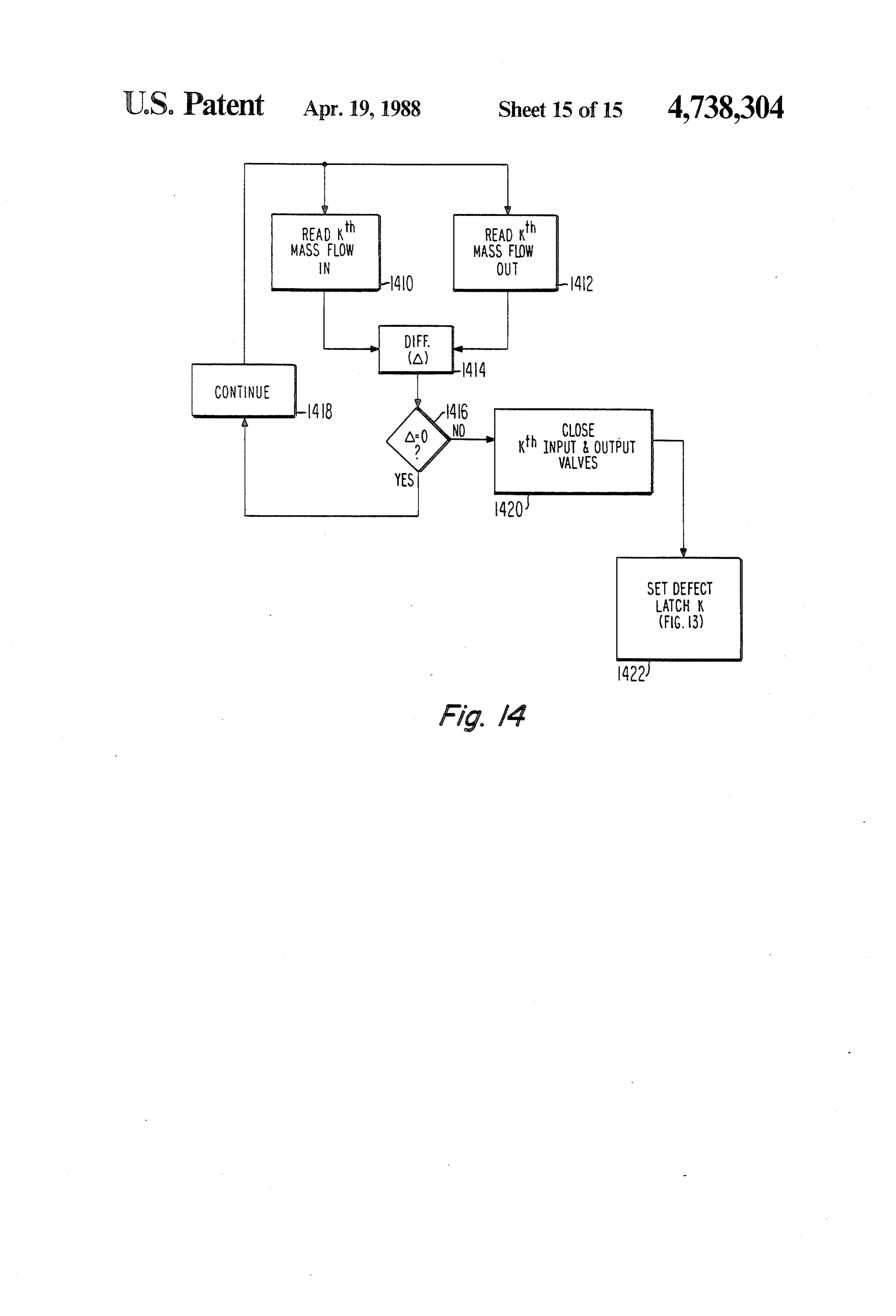
pressure sensor (for K= 1, sensor 1210) and the storage 55 As mentioned, the sequential operation and the time of a second pressure reading P2. Decision block 1320 delay required to make a test for small leaks may result represents a comparison of P2 with P1. If P2 equals P1, in loss of coolant due to a large rupture which empties the NO output of decision block 1320 indicates that the the cooling system quickly. FIG. 14 is a functional flow channel is intact, and directs the logic to a further block diagram representing one of K monitoring circuits, each 1322 which directs the opening of the Kth valves 60 of which is associated with one fluid channel. The ar (valves 1212 and 1214 of FIG. 12). The value of running rangement of FIG. 14 continually reads a mass flow variable K is incremented in block 1324 (to a value sensor such as mass flow sensor 1218' in a block 1410 K=2, for example), and its value is compared with a and reads a second mass sensor such as mass sensor value of M representing the end of a complete cycle of 1216' as represented by a second block 1412. The differ measurements. The value of M is predetermined and is 65 ence between the readings is generated in a block 1414, one greater than the number of channels to be tested. If and the results are applied to a decision block 1416. If K is less than M, the NO output of decision block 1326 the difference (A) is equal to zero, the YES output of directs the logic to a block 1328 which represents the decision block 1416 directs the logic by a CONTINUE
Page 22
path 1418 back to blocks 1410 and 1412 for further second channels from said vapor plenum has its readings of the input and output mass flow. If a large latent heat removed, and condenses to a liquid form leak or sudden rupture occurs, some of the fluid enter which in passing towards said liquid plenum fur ing the ruptured channel by way of mass flow sensor ther loses sensible heat and decreases in tempera 1218' will leak from the rupture rather than flowing ture, the environment of said space vehicle being through mass flow sensor 1216'. Difference block 1414 populated by micrometeroids possessing a distribu will immediately generate a finite difference signal, tion of kinetic energy ranging from insignificant which decision block 1416 will detect. The NO output amounts to amounts sufficient to penetrate the of decision block 1416 will direct the logic to a block walls of said pipe, which penetration might create 1420 which represents the closing of the input and out 10 an aperture in one of said first and second channels put valves 1212" and 1214 associated with defective through which said coolant can escape, thereby channel 240 of pipe 226. Since there is a major rupture rendering said heat transfer arrangement ineffec in channel 240, it is undesirable for the small leak sens tive;
ing system to continue testing channel 240. For this sensing and control means coupled to said fluid cou purpose, the logic flows from block 1420 to further 15 pling means and to said first and second fluid chan block 1422 which represents the setting to a logic high nels for sensing a coolant leak from one of said first (defect) of the output of the Kth defect latch (FIG. 13), and second fluid channels and for controlling said which corresponds to channel 240. It should be noted fluid coupling means for decoupling said vapor and that testing for ruptures does not require the use of liquid plenums from said one of said first and sec pressure sensors such as 1210", although they could be ond channels, whereby coolant fluid flow through used to verify the existence of a rupture. the other of said first and second channels main The described system closes off defective fluid chan tains a substantial amount of capacity of said heat nels in a multichannel pipe. This results in a reduction in transfer arrangement.
capacity, but the heat radiator with which the pipe is 2. A heat transfer arrangement according to claim 1 associated remains functional, so long as one or more 25 wherein said fluid coupling comprises first and second channels of the multichannel pipe remains operable. controllable valves for coupling said first and second Other embodiments of the invention will be apparent fluid channels, respectively, to said vapor plenum, and to those skilled in the art. In particular, any impact third and fourth controllable valves for coupling said resisting filler may be used for a filler within chambers first and second channels, respectively, to said liquid 50, 52 (FIG.2c); such a filler might be ceramic balls or 30 plenum.
"the like. Methods for detection of penetration of a cool 3. An arrangement according to claim 2 wherein said ant chamber other than those described may be used, sensing and control means comprises:
such as an acoustic sensor coupled to the fluid chamber first and second mass sensors coupled to said first and also coupled to a memory in which characteristic fluid channel near said first and second ends, re spectra of various types of punctures are stored for 35 spectively, of said pipe; comparison therewith. Other fittings, valves, coupling reading means coupled to said first and second mass and the like may be used for various other purposes flow sensors for reading said first and second mass associated with cooling without departing from the flow sensors to form first and second mass flow spirit of the invention. Rather than comparing two se signals;
quential pressure readings (P1 and P2 during the slow comparison means coupled to said reading means for leak test, the second pressure reading P2 may be com comparing said first and second mass flow signals pared with a predetermined reference value. and for generating a defect signal in response to a What is claimed is: difference therebetween; and 1. A heat transfer arrangement for removing heat valve control means coupled to said comparison from a space vehicle, comprising: 45 means and to said first and third valves for operat a vapor plenum adapted for receiving heat-laden ing said valves to a closed condition in response to coolant vapor for distributing said coolant vapor to said defect signal.
a plurality of vapor output ports; 4. A heat transfer arrangement according to claim 2 a liquid plenum including a plurality of input ports for wherein said sensing and control means comprises: receiving coolant liquid for collecting said coolant 50 first and second pressure sensing means coupled to liquid and for making said coolant liquid available said first and second channels, respectively; to a source of waste heat for cooling thereof; means for establishing a predetermined test period for a thermally conductive pipe including first and sec testing said first channel; ond ends and first and second independent fluid means for reading said first pressure sensing means channels extending therethrough from said first 55 before said predetermined test period and for stor end to said second end; ing a first pressure reading;
fluid coupling means coupled to said first and second means for operating said first and third valves to a fluid channels at said first and second ends, to said closed condition at the beginning of said predeter vapor and liquid plenums for controllably coupling mined test period;
coolant fluid through said first and second channels means for reading said first pressure sensing means from said vapor plenum to said liquid plenum; near the end of said predetermined test period to at least one thermally conductive radiator panel ther form a second pressure reading; mally coupled to said pipe and including a portion means for comparing said first and second pressure adapted for substantial black-body radiation into readings and for generating a defect signal in re space, whereby said pipe transfers heat from cool 65 sponse to a difference; and ant fluid flowing therethrough to said panel for means for operating said first and third valves to an radiation thereof, thereby cooling said fluid, open condition at the end of said predetermined whereby coolant vapor flowing into said first and test period in the absence of said defect signal and
Page 23
for leaving said first and third valves permanently said pipe-like structure, but an energetic microme closed in the presence of a defect signal, whereby teroid may nevertheless penetrate through said puncture of said first channel results in shutting off walls of said pipe-like structure, thereby forming said first channel but not said second channel to the an aperture through which said coolant can escape flow of coolant fluid. from one of said first and second channels; and 5. An arrangement according to claim 4 wherein said penetration sensing and control means coupled to sensing and control means comprises: said pipe-like structure and to said fluid coupling first and second mass sensors coupled to said first means for sensing the formation of an aperture fluid channel near said first and second ends, re through which said coolant can escape and for spectively, of said pipe; 10 controlling said coupling means for decoupling at reading means coupled to said first and second mass least one of said first and second Channels from flow sensors for reading said first and second mass both said vapor and liquid manifolds. flow sensors to form first and second mass flow 7. A radiator aocording to claim 6 wherein said elon signals; gated pipe-like structure is formed into a M-shaped comparison means coupled to said reading means for 15 curve in said plane.
comparing said first and second mass flow signals 8. A radiator according to claim 6 wherein said elon and for generating said defect signal in response to gated pipe-like structure is formed into a loop structure, a difference therebetween. whereby said elongated pipe-like structure crosses near 6. A heat radiator for a space vehicle, comprising: a crossover point, and said elongated pipe-like structure an elongated vapor manifold adapted for receiving 20 lies in said plane except near said crossover point. coolant vapor to be cooled; 9. A radiator according to claim 8 further comprising an elongated liquid manifold adapted for receiving a third bumper overlying said pipe-like structure near cooled liquid coolant, said elongated liquid mani said crossover point to thereby extend protection to said fold being arranged in a substantially parallel rela crossover region.
tionship with said elongated vapor manifold; 10. A radiator according to claim 6 wherein said first and second spaced-apart panels which are sub 25 penetration sensing and control means comprises a mass stantially planar and parallel over a principal por flow rate sensor coupled to one of said first and second tion of their area, said first and second panels being channels.
formed from heat-conductive material; 11. A radiator according to claim 6 wherein said an elongated pipe-like structure in the form of a ther penetration sensing and control means comprises: mally conductive multiple-channel pipe including 30 first and second mass flow sensors coupled to said first and second ends and an outer surface, and at first and second ends of said first channel, respec least first and second channels extending from said tively, for providing first and second mass flow first end to said second end, said elongated pipe signals indicative of the mass flow into and output like structure lying in a plane and being located of said first channel;
between said first and second panels with a portion 35 difference means coupled to said first and second of said outer surface thermally bonded to said first mass sensors for taking the difference between said panel and another portion of said outer surface first and second mass flow signals to produce a thermally bonded to said-second panel, and further difference signal;
being located with said first end adjacent said threshold comparison means coupled to said differ vapor manifold and said second end adjacent said ence means for comparison of said difference signal liquid manifold;
fluid coupling means coupled to said first and second with a reference level for producing a fault control ends of said pipe-like structure, and to said vapor signal indicative of puncture of said first channel; and liquid manifolds for controllably coupling at and least said first and second channels at one end of 45 second coupling means for coupling said fault control said first and second ends to said vapor manifold signal to said fluid coupling means for decoupling and at the other end of said first and second ends to said first channel from said vapor and liquid mani said liquid manifold, whereby micrometeroids in folds in response to said fault control signal. pinging upon said elongated pipe-like structure 12. A radiator according to claim 6 wherein said from a direction approximately normal to said 50 penetration sensing and control means comprises: plane are most likely to penetrate through the walls means for controlling said fluid coupling means for of said pipe-like structure thereby forming an aper temporarily decoupling said first fluid channel ture through which said coolant can escape; from said vapor and liquid manifolds for a prede a first elongated bumper located on a side of said first termined interval;
panel remote from said pipe-like structure, said first 55 means for sensing pressure in said first channel to bumper being dimensioned and located for inter produce a first pressure signal before said predeter cepting micrometeroids impinging on said first mined interval;
panel near said pipe-like structure from a direction means for storing said first pressure signal; approximately normal to said plane; means for sensing fluid pressure in said first channel a second elongated bumper located on a side of said during said predetermined interval to produce a second panel remote from said pipe-like structure, 60 second pressure signal;
said second bumper being dimensioned and located comparison means for comparing said first and sec for intercepting micrometeroids impinging on said ond pressure signals and for generating a fault in second panel near said pipe-like structure from a dicative signal if said signals differ; and direction approximately normal to said plane, means for controlling said fluid coupling means for whereby a micrometeroid must penetrate one of 65 coupling said first channel with said vapor and said first or second bumpers and a corresponding liquid manifolds in the absence of said fault indica one of said first and second panels before it can tive signal.
transfer a substantial amount of its kinetic energy to t : t s
Provenance
- Collection
- Cited prior art
- Original PDF
- patentimages.storage.googleapis.com →
- Filed
- 1986-03-12
- Pages
- 23
- Method
- pdftotext (the PDF's own text layer) + pdftoppm 300dpi page scans
- Source
- Google Patents bibliographic record
- Granted
- 1988-04-19
- Inventors
- Douglas R. Chalmers; John J. Pustay; RCA Corp
- Transcribed from
- patentimages.storage.googleapis.com →