patent · US5079681
Illuminating apparatus
7 January 1992
Page 1 — bibliographic record
HHHHHH
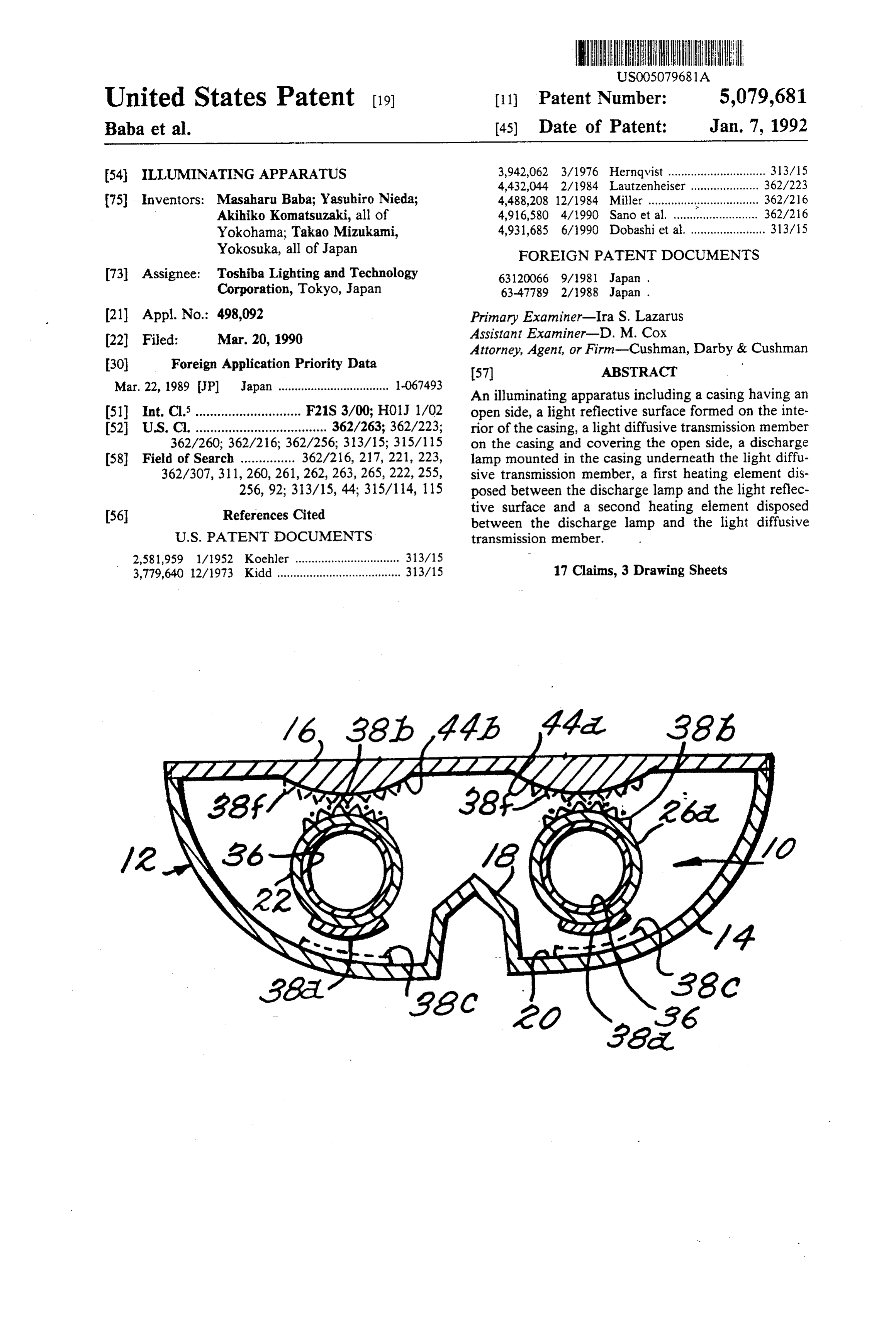
United States Patent (19) 11 Patent Number: 5,079,681 Baba et al. (45) Date of Patent: Jan. 7, 1992 54). ILLUMINATINGAPPARATUS 3,942,062 3/1976 Herndvist .............................. 313/15
75) Inventors: Masaharu Baba; Yasuhiro Nieda; 4,488,208 12/1984 Miller ................ . . ... 362/216 Akihiko Komatsuzaki, all of 4,916,580 4/1990 Sano et al. .......... ... 362/26 Yokohama; Takao Mizukami, 4,931,685 6/1990 Dobashi et al. ..................33/15 Yokosuka, all of Japan FOREIGN PATENT DOCUMENTS 73 Assignee: Toshiba Lighting and Technology 63120066 9/1981 Japan. Corporation, Tokyo, Japan 63-47789 2/1988 Japan.
(21) Appl. No.: 498,092 Primary Examiner-Ira S. Lazarus 22 Filed: Mar. 20, 1990 Assistant Examiner-D. M. Cox Attorney, Agent, or Firm-Cushman, Darby & Cushman 30 Foreign Application Priority Data (57) ABSTRACT Mar. 22, 1989 JP Japan .................................. -067493 An illuminating apparatus including a casing having an 51) Int. Cl.............................. F21S 3/00; H01J 1/02 open side, a light reflective surface formed on the inte 52 U.S. Cl. .................................... 362/263; 362/223; rior of the casing, a light diffusive transmission member 362/260; 362/216; 362/256; 313/15; 315/115 on the casing and covering the open side, a discharge 58) Field of Search ............... 362/216, 217, 221, 223, lamp mounted in the casing underneath the light diffu 362/307, 311, 260,261,262, 263,265, 222, 255, sive transmission member, a first heating element dis 256, 92; 313/15, 44; 315/114, 115 posed between the discharge lamp and the light reflec 56 References Cited tive surface and a second heating element disposed between the discharge lamp and the light diffusive
2,581,959 1/1952 Koehler ................................ 313/15 3,779,640 12/1973 Kidd...................................... 313/15 17 Claims, 3 Drawing Sheets
SAA an asS
Page 2
Drawing sheet — no readable text.
Page 3
Drawing sheet — no readable text.
Page 4
Drawing sheet — no readable text.
Page 5
heater accelerates the evaporation of the mercury in the
ILLUMINATING APPARATUS low pressure mercury vapor discharge lamp without disturbing the illumination for the liquid crystal display
The present invention relates to an illuminating appa In a conventional illuminating apparatus, a laminate ratus, and more particularly, to a low pressure mercury heater is attached on the low pressure mercury vapor vapor discharge lamp illuminating apparatus. discharge lamp by a tubular fixing member such as a thermo-shrinkage tube. The thermo-shrinkage tube
BACKGROUND OF THE INVENTION keeps the low pressure mercury vapor discharge lamp Recently, a liquid crystal display device is used in O warm. However, when the low pressure mercury vapor many fields. For example, a digital meter using such a discharge lamp is formed into a complicated shape, such liquid crystal display device is provided on an instru as a U-letter shape, a W-letter shape, etc., it is difficult to ment panel of automobiles. The liquid crystal display make the shape of the laminate heater conform to the device is generally provided most of its illumination by 15 shape of the low pressure mercury vapor discharge an illuminating apparatus. Such an illuminating appara lamp. It is also difficult to fit the thermo-shrinkage tube tus is referred to as a back-illuminating apparatus. The on the low pressure mercury vapor discharge lamp for back-illuminating apparatus must illuminate uniformly fixing the laminate heater.
the overall surface of the liquid crystal display device. In another conventional illuminating apparatus, a The back-illuminating apparatus is typically con 20 print circuit type heater is coated on the low pressure structed using a low pressure mercury vapor discharge mercury vapor discharge lamp. This type heater is lamp such as a fluorescent lamp and a casing for housing formed by a resistive material such as a silver (Ag) the low pressure mercury vapor discharge lamp. The paste. An illuminating apparatus of this type is disclosed casing has a light diffusion plate on one side and a re in Japanese Patent Disclosure Tokkai-Sho 56-120066. flector on the other side. The illuminating apparatus is In the latter conventional illuminating apparatus, the applied to the liquid crystal display device so that the 25 printed heater can be easily conformed to the shape of light diffusion plate faces toward the liquid crystal dis the low pressure mercury vapor discharge lamp, even if play device. Thus, the light diffusive transmission plate the low pressure mercury vapor discharge lamp is diffusively transmits both the light directly radiated.
from the low pressure mercury vapor discharge lamp formed in a complicated shape. However, the surface of the low pressure mercury
and the light reflected from the reflector. The diffused vapor discharge lamp not coated with the printed light from the light diffusion plate is uniformly applied heater is exposed, so that low pressure mercury vapor to the overall surface of the liquid crystal display de discharge lamps of this type are difficult to keep warm. Vice.
When
The low pressure mercury vapor discharge lamp has discharge lamp gaps between the low pressure mercury vapor and the light diffusion plate and the a higher illuminating efficiency, less heat generation 35 reflector are decreased and a longer life in comparison to incandescent bulbs. to allow thinning of the size of Moreover, the low pressure mercury vapor discharge the illuminating apparatus, the sides of the low pressure mercury vapor discharge lamp facing the light diffusion lamp has a relatively large light-emitting area due to its plate and the reflector are undesirably cooled. Thus, long discharge path. Also, the shape of the discharge path of the low pressure mercury vapor discharge lamp this latter type of conventional illuminating apparatus is may be freely formed, for instance, into a U-letter also not able to operate quickly at low ambient tempera tures.
shape, a W-letter shape, etc. Thus, the illuminating apparatus using the low pressure mercury vapor dis In addition, the prior art illumination devices suffer charge lamp is advantageously able to perform a uni from a flaw in that the light they emit is often not prop form illumination for the liquid crystal display device. 45 erly diffused. This often results in bright and dark por However, the low pressure mercury vapor discharge tions, or shadows, when even illumination is required. lamp takes a relatively long time to reach a rated bright SUMMARY OF THE INVENTION ness. It especially takes a long time in a low ambient temperature. This is because the mercury sealed in the It is, therefore, an object of the present invention to low pressure mercury vapor discharge lamp does not 50 provide an illuminating apparatus which is able to start vaporize as well in low ambient temperatures. Further quickly at a relatively low ambient temperature. more, the light diffusion plate and the reflector severely Another object of the present invention is to provide absorb the heat of the discharge lamp when they are an illuminating apparatus in which a heater provided on close to each other for reducing the size of the illumi a low pressure mercury vapor discharge lamp is able to nating apparatus. 55 warm the lamp without disturbing the illumination. For example, automobiles are required to operate in In order to achieve the above object, an illuminating an ambient temperature range from approximately apparatus according to one aspect of the present inven --40 C. to approximately -30° C. Therefore, the low tion includes a casing having an open side, a light reflec pressure mercury vapor discharge lamp is required to tive surface formed on the interior of the casing, a light start rapidly and to operate in such a low ambient tem diffusive transmission member on the casing and cover perature, e.g., -30° C. ing the open side, a discharge lamp mounted in the Conventionally, a heater is provided on the low pres casing underneath the light diffusive transmission mem sure mercury vapor discharge lamp for quickening the ber, a first heating element disposed between the dis start of the operation. Such a heater is attached to the charge lamp and light reflective surface, and a second low pressure mercury vapor discharge lamp at a side 65 heating element disposed between the discharge lamp where the heater does not face to the light diffusion and the light diffusive transmission member. plate. Generally, such a heater is placed on the side Additional objects and advantages of the present where the heater faces the reflector. As a result, the invention will be apparent to persons skilled in the art
Page 6
from a study of the following description and the ac Fluorescent lamp 10 is further provided with a pair of companying drawings, which are hereby incorporated heaters 38a and 38b. Heaters 38a and 38b are coated on in and constitute a part of this specification. the outer surface of bulb. 22. For example, heaters 38a BRIEF DESCRIPTION OF THE DRAWINGS and 38b are formed by printing resistive material, as described later. Heaters 38a and 38b are formed in an
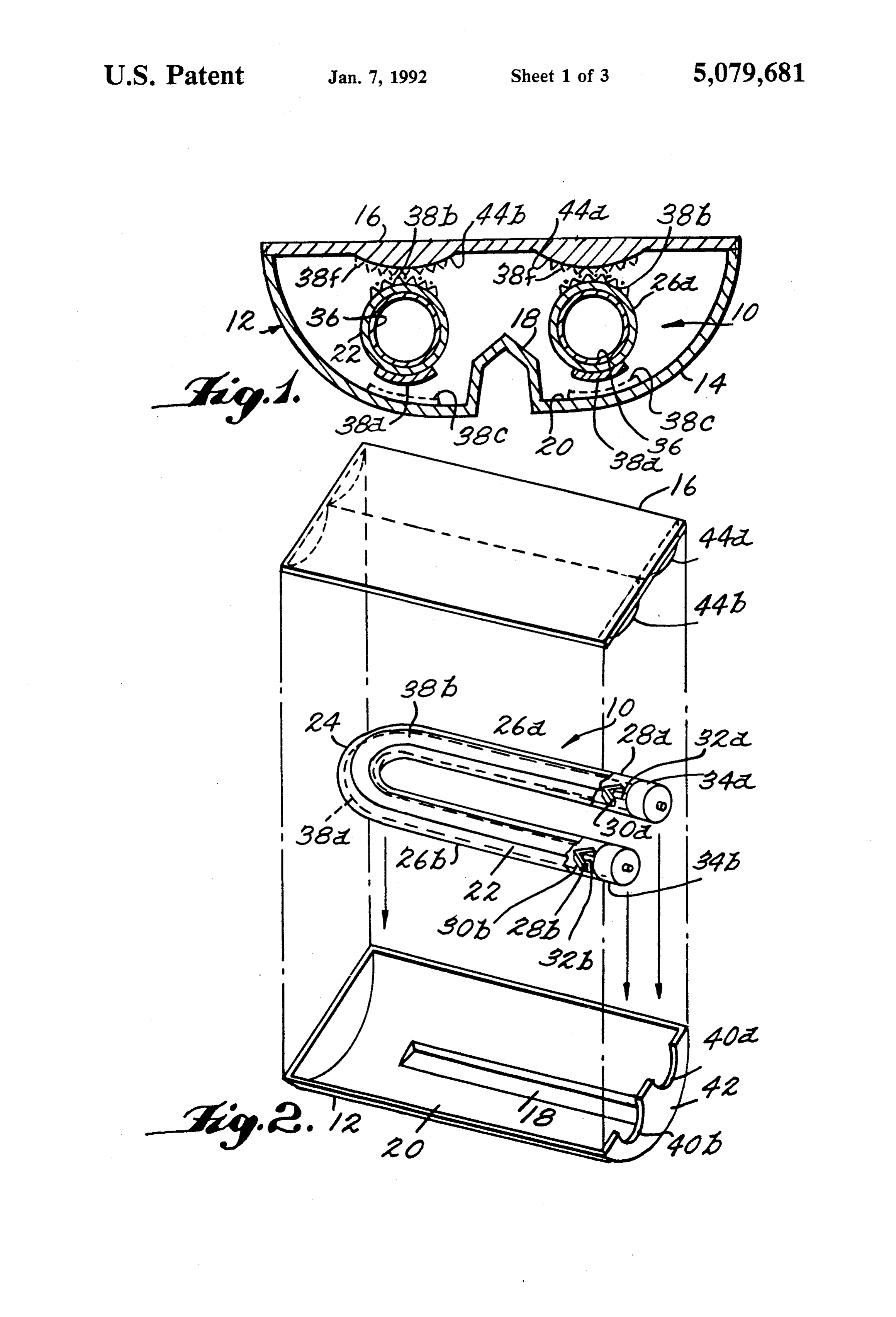
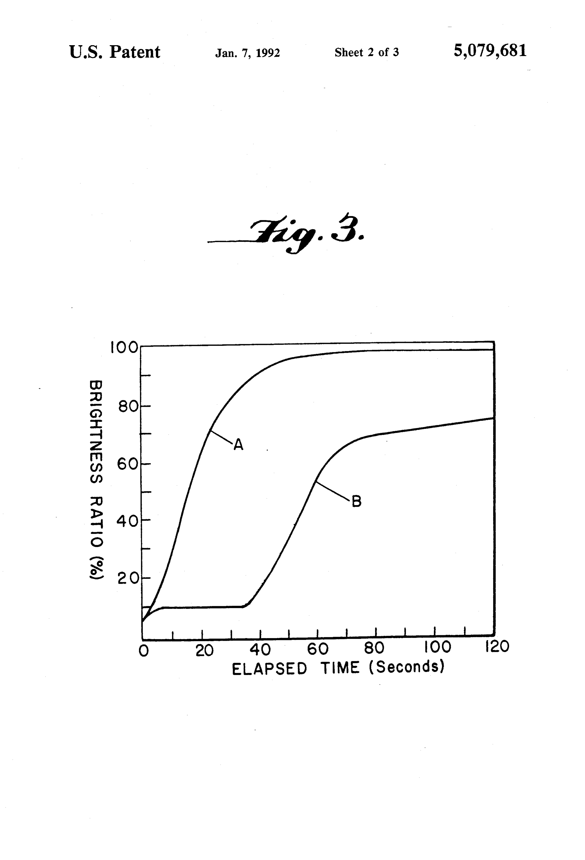
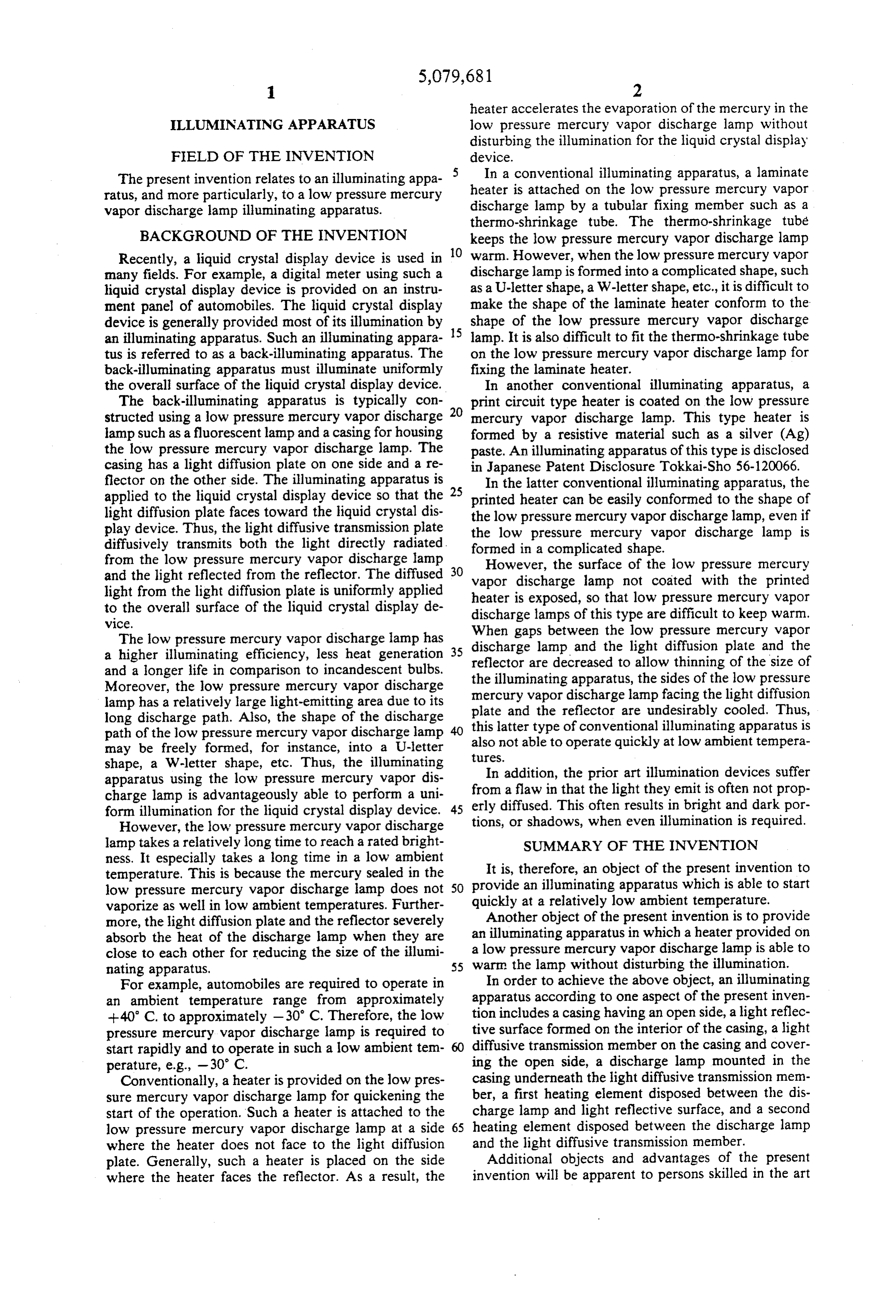
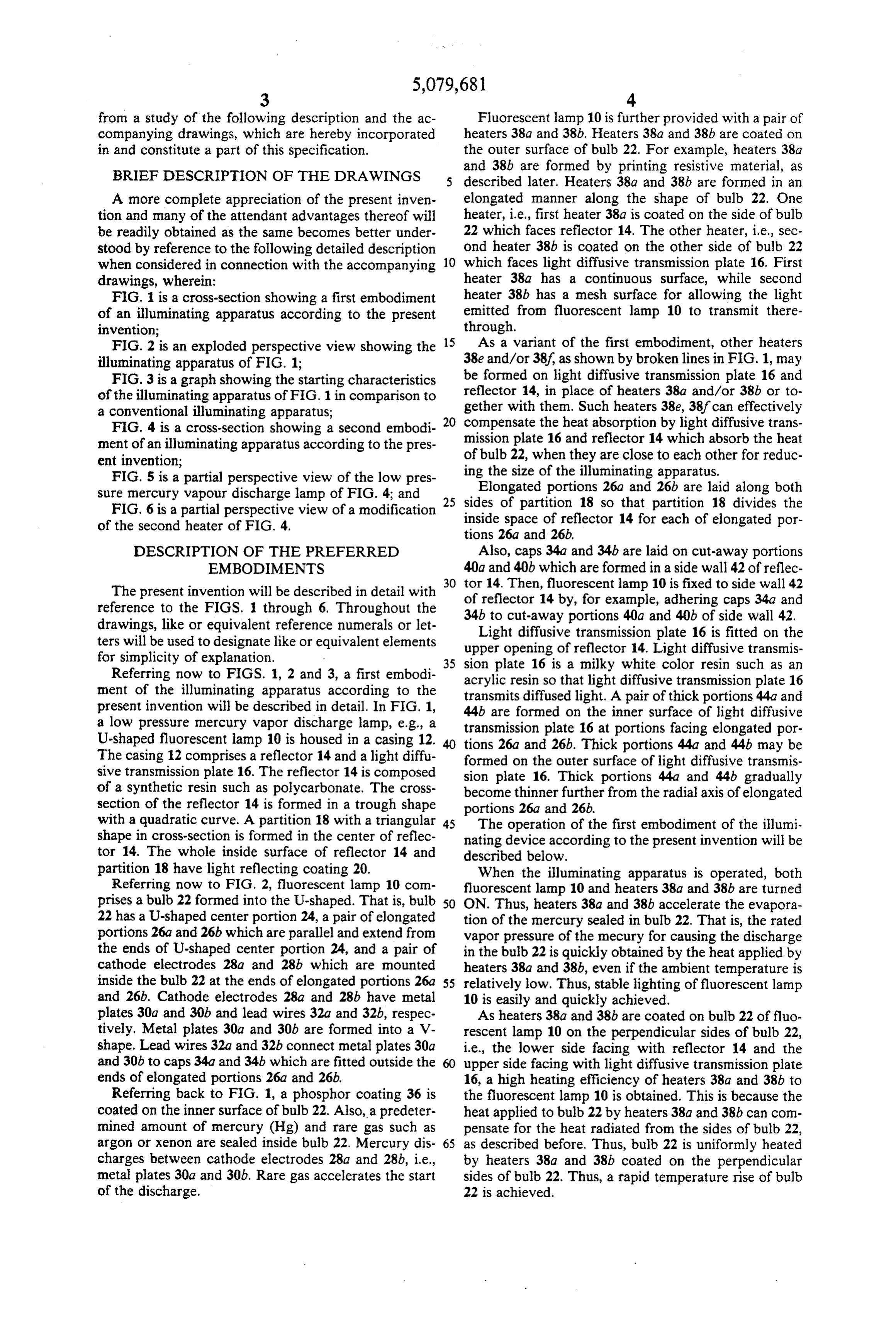
A more complete appreciation of the present inven elongated manner along the shape of bulb. 22. One tion and many of the attendant advantages thereof will heater, i.e., first heater 38a is coated on the side of bulb be readily obtained as the same becomes better under 22 which faces reflector 14. The other heater, i.e., sec stood by reference to the following detailed description ond heater 38b is coated on the other side of bulb 22 when considered in connection with the accompanying 10 which faces light diffusive transmission plate 16. First drawings, wherein: heater 38a has a continuous surface, while second FIG. 1 is a cross-section showing a first embodiment heater 38b has a mesh surface for allowing the light of an illuminating apparatus according to the present emitted from fluorescent lamp 10 to transmit there invention; through.
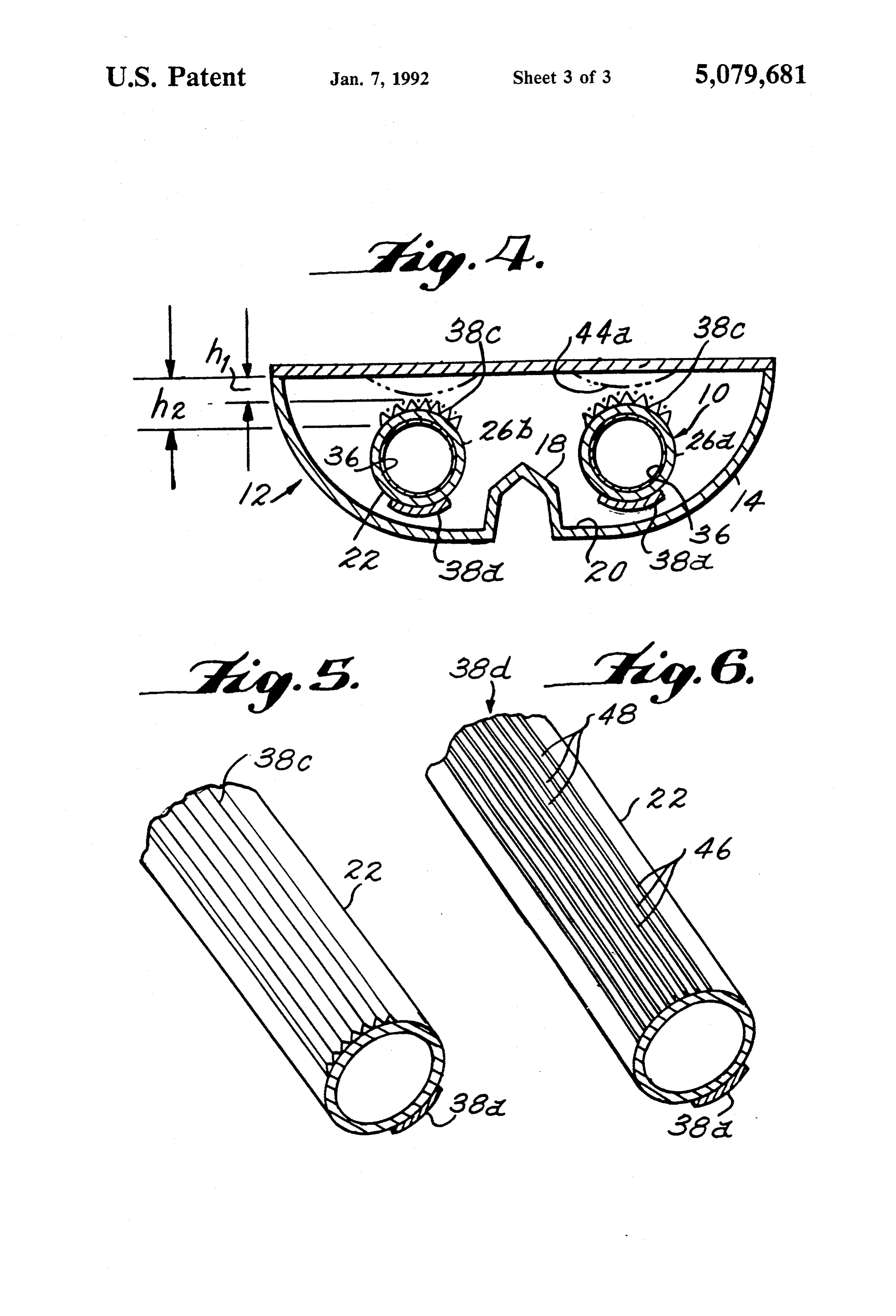
FIG. 2 is an exploded perspective view showing the 15 As a variant of the first embodiment, other heaters illuminating apparatus of FIG. 1; 38e and/or 38?, as shown by broken lines in FIG. 1, may FIG. 3 is a graph showing the starting characteristics be formed on light diffusive transmission plate 16 and of the illuminating apparatus of FIG. 1 in comparison to reflector 14, in place of heaters 38a and/or 38b or to a conventional illuminating apparatus; gether with them. Such heaters 38e, 38f can effectively FIG. 4 is a cross-section showing a second embodi 20 compensate the heat absorption by light diffusive trans ment of an illuminating apparatus according to the pres mission plate 16 and reflector 14 which absorb the heat ent invention; of bulb 22, when they are close to each other for reduc FIG. 5 is a partial perspective view of the low pres ing the size of the illuminating apparatus. sure mercury vapour discharge lamp of FIG. 4; and 25 sides Elongated portions 26a and 26b are laid along both FIG. 6 is a partial perspective view of a modification inside ofspace partition 18 so that partition 18 divides the of reflector 14 for each of elongated por of the second heater of FIG. 4.
tions 26a and 26b,
DESCRIPTION OF THE PREFERRED Also, caps 34a and 34b are laid on cut-away portions EMBODIMENTS 40a and 40b which are formed in a side wall 42 of reflec 30 tor 14. Then, fluorescent lamp 10 is fixed to side wall 42
The present invention will be described in detail with of reflector 14 by, for example, adhering caps 34a and reference to the FIGS. 1 through 6. Throughout the 34b to cut-away portions 40a and 40b of side wall 42. drawings, like or equivalent reference numerals or let Light diffusive transmission plate 16 is fitted on the ters will be used to designate like or equivalent elementsupper opening of reflector 14. Light diffusive transmis for simplicity of explanation. 35 sion plate 16 is a milky white color resin such as an Referring now to FIGS. 1, 2 and 3, a first embodi ment of the illuminating apparatus according to the acrylic resin so that light diffusive transmission plate 16 transmits diffused light. A pair of thick portions 44a and present invention will be described in detail. In FIG. 1, a low pressure mercury vapor discharge lamp, e.g., a 44b are formed on the inner surface of light diffusive transmission plate 16 at portions facing elongated por
U-shaped fluorescent lamp 10 is housed in a casing 12.
The casing 12 comprises a reflector 14 and a light diffu tions formed 26a and 26b. Thick portions 44a and 44b may be on the outer surface of light diffusive transmis sive transmission plate 16. The reflector 14 is composed sion plate 16. Thick portions 44a and 44b gradually of a synthetic resin such as polycarbonate. The cross become thinner further from the radial axis of elongated section of the reflector 14 is formed in a trough shape portions 26a and 26b.
with a quadratic curve. A partition 18 with a triangular 45 The operation of the first embodiment of the illumi shape in cross-section is formed in the center of reflec nating device according to the present invention will be tor 14. The whole inside surface of reflector 14 and described below.
partition 18 have light reflecting coating 20. When the illuminating apparatus is operated, both Referring now to FIG. 2, fluorescent lamp 10 com fluorescent lamp 10 and heaters 38a and 38b are turned prises a bulb 22 formed into the U-shaped. That is, bulb 50 ON. Thus, heaters 38a and 38b accelerate the evapora 22 has a U-shaped center portion 24, a pair of elongated tion of the mercury sealed in bulb. 22. That is, the rated portions 26a and 26b which are parallel and extend from vapor pressure of the mecury for causing the discharge the ends of U-shaped center portion 24, and a pair of in the bulb 22 is quickly obtained by the heat applied by cathode electrodes 28a and 28b which are mounted heaters 38a and 38b, even if the ambient temperature is inside the bulb 22 at the ends of elongated portions 26a 55 relatively low. Thus, stable lighting of fluorescent lamp and 26b. Cathode electrodes 28a and 28b have metal 10 is easily and quickly achieved. plates 30a and 30b and lead wires 32a and 32b, respec As heaters 38a and 38b are coated on bulb 22 of fluo tively. Metal plates 30a and 30b are formed into a V rescent lamp 10 on the perpendicular sides of bulb 22, shape. Lead wires 32a and 32b connect metal plates 30a i.e., the lower side facing with reflector 14 and the and 30b to caps 34a and 34b which are fitted outside the upper side facing with light diffusive transmission plate ends of elongated portions 26a and 26b. 16, a high heating efficiency of heaters 38a and 38b to Referring back to FIG. 1, a phosphor coating 36 is the fluorescent lamp 10 is obtained. This is because the coated on the inner surface of bulb. 22. Also, a predeter heat applied to bulb 22 by heaters 38a and 38b can com mined amount of mercury (Hg) and rare gas such as pensate for the heat radiated from the sides of bulb 22, argon or xenon are sealed inside bulb. 22. Mercury dis 65 as described before. Thus, bulb 22 is uniformly heated charges between cathode electrodes 28a and 28b, i.e., by heaters 38a and 38b coated on the perpendicular metal plates 30a and 30b. Rare gas accelerates the start sides of bulb 22. Thus, a rapid temperature rise of bulb of the discharge. 22 is achieved.
Page 7
The rapid temperature rise of bulb. 22 accelerates the 40 seconds elapsed. Then, the brightness of sample A evaporation of the mercury sealed in bulb. 22. Thus, the gradually rose to the 98% level. On the other hand, the vapor pressure of the mercury quickly reaches the rated brightness of sample B was depressed to 10% of the value and excites the discharge lighting of the fluores rated brightness until after about 35 seconds had cent lamp 10. As a result, the rated brightness is rapidly elapsed. Then, the brightness of sample B began to rise. achieved. However, once the brightness of sample B had reached Second heater 38b coated on the upper side of bulb 22 about 70% of the rated value, it rose very slowly there facing the light diffusive transmission plate 16 is formed after. As shown in FIG. 3, it is easily understood that as a mesh pattern for allowing the light emitted from the illumination characteristics of the illuminating appa fluorescent lamp 10 to transmit therethrough. Thus, O ratus according to the present invention is remarkably second heater 38b is able to heat bulb 22 without dis improved.
turbing the light transmission from fluorescent lamp 10 In the first embodiment of the illuminating apparatus, to an object to be illuminated, e.g., a liquid crystal dis second heater 38b coated on the upper side of bulb 22 is play device. formed as a mesh pattern. The forming of the mesh can When fluorescent lamp 10 is turned ON, a part of the 15 be achieved by a well-known printing technique. Thus, light emitted from fluorescent lamp 10 is directly ap it does not require much labor.
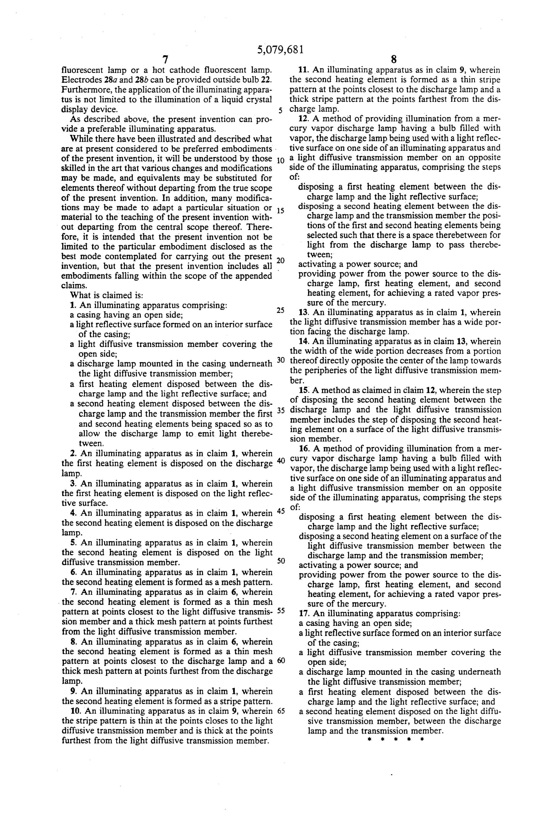
plied to light diffusive transmission plate 16. Part of the The present invention is not limited to the embodi light is also applied thereto by reflection from reflector ment described above. For example, FIGS. 4 and 5 14. The whole light thus diffusively transmits through show a second embodiment of the illuminating appara light diffusive transmission plate 16 and illuminates the 20 tus according to the present invention. The second object such as the liquid crystal display device. embodiment of the illuminating apparatus is almost As reflector 14 has a quadratic curve, the light ap equivalent to the first embodiment, except for a second plied to reflector 14 is efficiently reflected towards light heater 38c coated on the upper side of bulb 22 facing the diffusive transmission plate 16. Further, as partition 18 light diffusive transmission plate 16. Thus, the following is placed between elongated portions 26a and 26b of 25 explanation of the second embodiment will be focused bulb 22, partition 18 increases the light reflecting effi on second heater 38c, ciency. Thus the light illumination of the illuminating In FIG. 4, second heater 38c is also formed in a mesh apparatus is increased. similar to second heater 38b of the first embodiment. Furthermore, thick portions 44a and 44b are formed However, the central part of second heater 38c of the on light diffusive transmission plate 16, as described 30 second embodiment is finely meshed. The mesh gradu above. The light transmissivity of thick portions 44a ally becomes coarse towards the peripherals of second and 44b gradually increases from their peripherals to heater 38c.
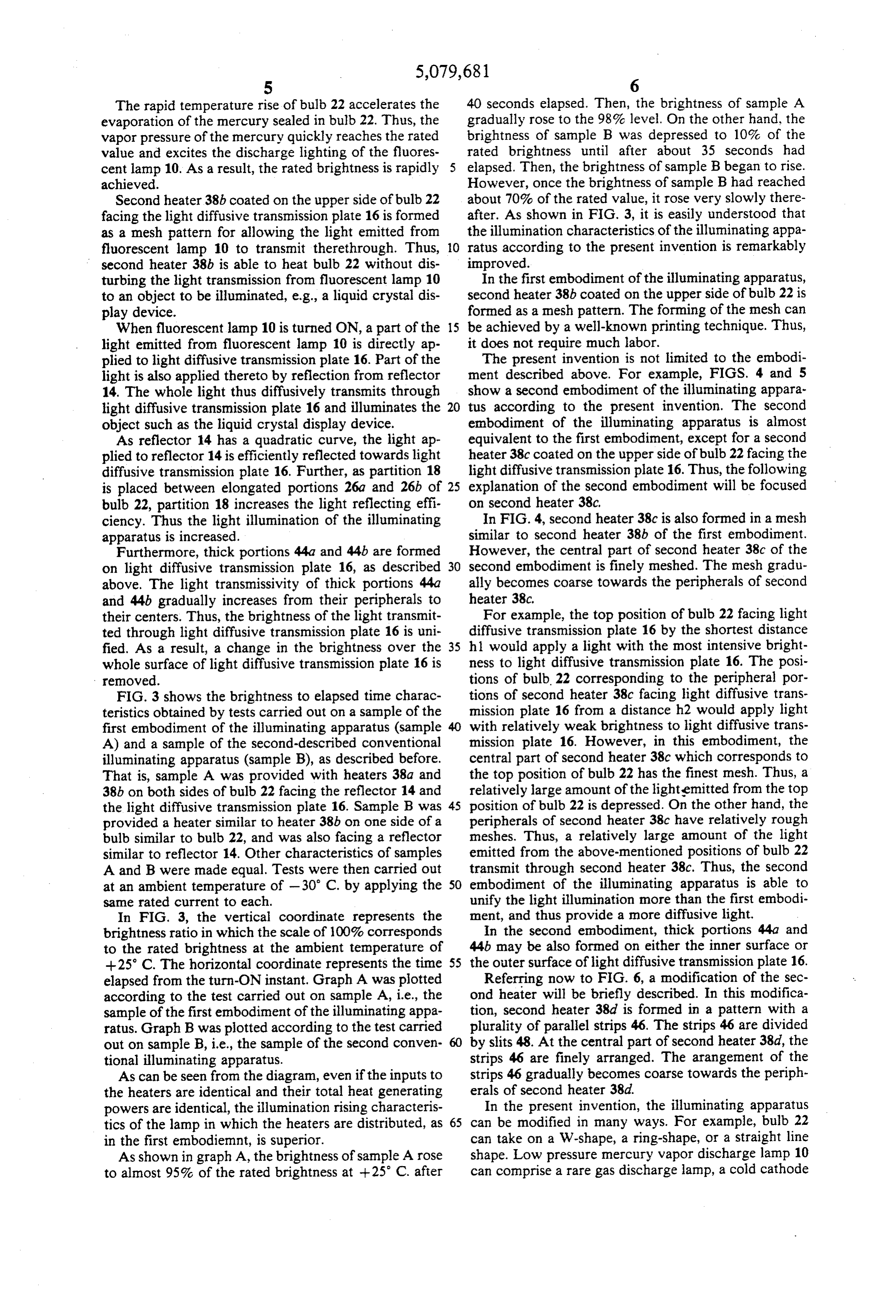
their centers. Thus, the brightness of the light transmit For example, the top position of bulb 22 facing light ted through light diffusive transmission plate 16 is uni diffusive transmission plate 16 by the shortest distance fied. As a result, a change in the brightness over the 35 hl would apply a light with the most intensive bright whole surface of light diffusive transmission plate 16 is ness to light diffusive transmission plate 16. The posi removed. tions of bulb. 22 corresponding to the peripheral por FIG. 3 shows the brightness to elapsed time charac tions of second heater 38c facing light diffusive trans teristics obtained by tests carried out on a sample of the mission plate 16 from a distance h2 would apply light first embodiment of the illuminating apparatus (sample 40 with relatively weak brightness to light diffusive trans A) and a sample of the second-described conventional mission plate 16. However, in this embodiment, the illuminating apparatus (sample B), as described before. central part of second heater 38c which corresponds to That is, sample A was provided with heaters 38a and the top position of bulb 22 has the finest mesh. Thus, a 38b on both sides of bulb 22 facing the reflector 14 and relatively large amount of the light-emitted from the top the light diffusive transmission plate 16. Sample B was 45 position of bulb 22 is depressed. On the other hand, the provided a heater similar to heater 38b on one side of a peripherals of second heater 38c have relatively rough bulb similar to bulb 22, and was also facing a reflector meshes. Thus, a relatively large amount of the light similar to reflector 14. Other characteristics of samples emitted from the above-mentioned positions of bulb 22 A and B were made equal. Tests were then carried out transmit through second heater 38c. Thus, the second at an ambient temperature of -30° C. by applying the 50 embodiment of the illuminating apparatus is able to same rated current to each. unify the light illumination more than the first embodi In FIG. 3, the vertical coordinate represents the ment, and thus provide a more diffusive light. brightness ratio in which the scale of 100% corresponds In the second embodiment, thick portions 44a and to the rated brightness at the ambient temperature of 44b may be also formed on either the inner surface or +25°C. The horizontal coordinate represents the time 55 the outer surface of light diffusive transmission plate 16. elapsed from the turn-ON instant. Graph A was plotted Referring now to FIG. 6, a modification of the sec according to the test carried out on sample A, i.e., the ond heater will be briefly described. In this modifica sample of the first embodiment of the illuminating appa tion, second heater 38d is formed in a pattern with a ratus. Graph B was plotted according to the test carried plurality of parallel strips 46. The strips 46 are divided out on sample B, i.e., the sample of the second conven 60 by slits 48. At the central part of second heater 38d, the tional illuminating apparatus. strips 46 are finely arranged. The arangement of the As can be seen from the diagram, even if the inputs to strips 46 gradually becomes coarse towards the periph the heaters are identical and their total heat generating erals of second heater 38d.
powers are identical, the illumination rising characteris In the present invention, the illuminating apparatus tics of the lamp in which the heaters are distributed, as 65 can be modified in many ways. For example, bulb 22 in the first embodiemnt, is superior. can take on a W-shape, a ring-shape, or a straight line As shown in graph A, the brightness of sample A rose shape. Low pressure mercury vapor discharge lamp 10 to almost 95% of the rated brightness at +25° C. after can comprise a rare gas discharge lamp, a cold cathode
Page 8
fluorescent lamp or a hot cathode fluorescent lamp. 11. An illuminating apparatus as in claim 9, wherein Electrodes 28a and 28b can be provided outside bulb. 22. the second heating element is formed as a thin stripe Furthermore, the application of the illuminating appara pattern at the points closest to the discharge lamp and a tus is not limited to the illumination of a liquid crystal thick stripe pattern at the points farthest from the dis display device. charge lamp,
As described above, the present invention can pro 12. A method of providing illumination from a mer vide a preferable illuminating apparatus. cury vapor discharge lamp having a bulb filled with While there have been illustrated and described what vapor, the discharge lamp being used with a light reflec are at present considered to be preferred embodiments tive surface on one side of an illuminating apparatus and of the present invention, it will be understood by those O a light diffusive transmission member on an opposite skilled in the art that various changes and modifications side of the illuminating apparatus, comprising the steps may be made, and equivalents may be substituted for of:
elements thereof without departing from the true scope disposing a first heating element between the dis of the present invention. In addition, many modifica charge lamp and the light reflective surface; tions may be made to adapt a particular situation or 15 disposing a second heating element between the dis material to the teaching of the present invention with charge lamp and the transmission member the posi out departing from the central scope thereof. There tions of the first and second heating elements being fore, it is intended that the present invention not be selected such that there is a space therebetween for limited to the particular embodiment disclosed as the light from the discharge lamp to pass therebe best mode contemplated for carrying out the present 20 tween;
invention, but that the present invention includes all activating a power source; and embodiments falling within the scope of the appended providing power from the power source to the dis claims. charge lamp, first heating element, and second What is claimed is: heating element, for achieving a rated vapor pres 1. An illuminating apparatus comprising: sure of the mercury.
25 13. An illuminating apparatus as in claim 1, wherein a casing having an open side;
a light reflective surface formed on an interior surface the light diffusive transmission member has a wide por tion facing the discharge lamp.
of the casing:
a light diffusive transmission member covering the 14. An illuminating apparatus as in claim 13, wherein open side; the width of the wide portion decreases from a portion a discharge lamp mounted in the casing underneath 30 thereof directly opposite the center of the lamp towards the light diffusive transmission member; the peripheries of the light diffusive transmission mem a first heating element disposed between the dis ber.15. A method as claimed in claim 12, wherein the step charge lamp and the light reflective surface; and a second heating element disposed between the dis 35 of disposing the second heating element between the discharge lamp and the light diffusive transmission charge lamp and the transmission member the first member includes the step of disposing the second heat and second heating elements being spaced so as to ing allow the discharge lamp to emit light therebe sionelement member.
on a surface of the light diffusive transmis tween 2. An illuminating apparatus as in claim 1, wherein cury vapor 16. A method of providing illumination from a mer the first heating element is disposed on the discharge vapor, the discharge discharge lamp having a bulb filled with lamp. lamp being used with a light reflec 3. An illuminating apparatus as in claim 1, wherein tive surface on one side of an illuminating apparatus and the first heating element is disposed on the light reflec asidelight diffusive transmission member on an opposite of the illuminating apparatus, comprising the steps tive surface. of:
4. An illuminating apparatus as in claim 1, wherein 45 the second heating element is disposed on the discharge disposing a first heating element between the dis lamp. charge lamp and the light reflective surface; 5. An illuminating apparatus as in claim 1, wherein disposing a second heating element on a surface of the the second heating element is disposed on the light light diffusive transmission member between the diffusive transmission member. SO discharge lamp and the transmission member; activating a power source; and 6. An illuminating apparatus as in claim 1, wherein providing power from the power source to the dis the second heating element is formed as a mesh pattern. charge lamp, first heating element, and second 7. An illuminating apparatus as in claim 6, wherein heating element, for achieving a rated vapor pres the second heating element is formed as a thin mesh sure of the mercury.
pattern at points closest to the light diffusive transmis 55 17. An illuminating apparatus comprising: sion member and a thick mesh pattern at points furthest a casing having an open side; from the light diffusive transmission member. a light reflective surface formed on an interior surface 8. An illuminating apparatus as in claim 6, wherein of the casing;
the second heating element is formed as a thin mesh a light diffusive transmission member covering the pattern at points closest to the discharge lamp and a open side;
thick mesh pattern at points furthest from the discharge a discharge lamp mounted in the casing underneath lamp. the light diffusive transmission member; 9. An illuminating apparatus as in claim 1, wherein a first heating element disposed between the dis the second heating element is formed as a stripe pattern. charge lamp and the light reflective surface; and 10. An illuminating apparatus as in claim 9, wherein 65 a second heating element disposed on the light diffu the stripe pattern is thin at the points closes to the light sive transmission member, between the discharge diffusive transmission member and is thick at the points lamp and the transmission member. furthest from the light diffusive transmission member. k s k
Provenance
- Collection
- Cited prior art
- Original PDF
- patentimages.storage.googleapis.com →
- Filed
- 1990-03-20
- Pages
- 8
- Method
- pdftotext (the PDF's own text layer) + pdftoppm 300dpi page scans
- Source
- Google Patents bibliographic record
- Granted
- 1992-01-07
- Inventors
- Masaharu Baba; Yasuhiro Nieda; Akihiko Komatsuzaki; Takao Mizukami; Toshiba Lighting and Technology Corp
- Transcribed from
- patentimages.storage.googleapis.com →