patent · US5074258
Intake system for multiple-cylinder engine
24 December 1991
Page 1 — bibliographic record
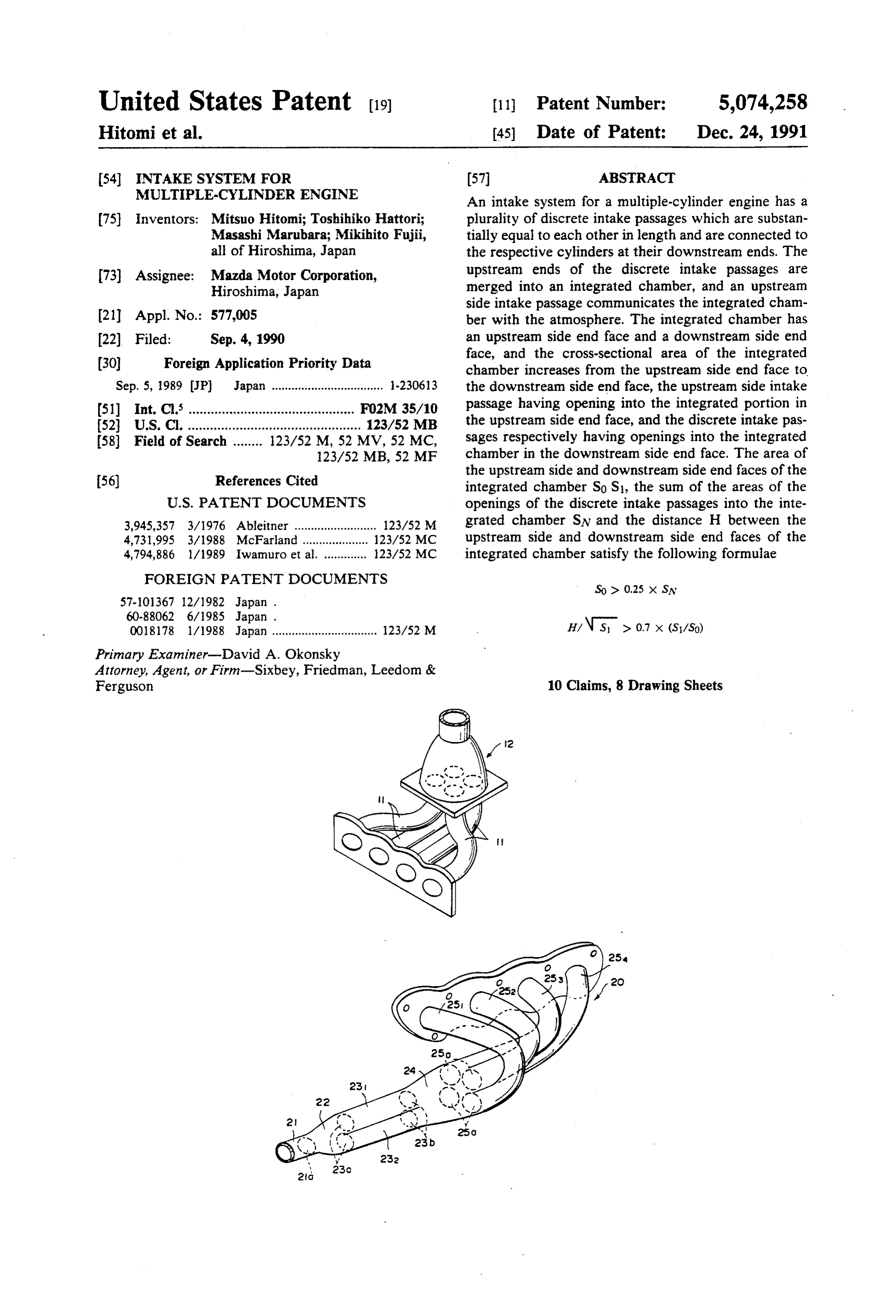
United States Patent (19) 11) Patent Number: 5,074,258 Hitomi et al. 45) Date of Patent: Dec. 24, 1991 54 INTAKE SYSTEM FOR 57 ABSTRACT MULTIPLE-CYLNDER ENGINE An intake system for a multiple-cylinder engine has a 75) Inventors: Mitsuo Hitomi; Toshihiko Hattori; plurality of discrete intake passages which are substan Masashi Marubara; Mikihito Fujii, tially equal to each other in length and are connected to all of Hiroshima, Japan the respective cylinders at their downstream ends. The 73) Assignee: Mazda Motor Corporation, upstream ends of the discrete intake passages are Hiroshima, Japan merged into an integrated chamber, and an upstream side intake passage communicates the integrated cham 21 Appl. No.: 577,005 ber with the atmosphere. The integrated chamber has 22 Filed: Sep. 4, 1990 an upstream side end face and a downstream side end 30 Foreign Application Priority Data face, and the cross-sectional area of the integrated chamber increases from the upstream side end face to
Sep. 5, 1989 JP Japan .................................. -23063 the downstream side end face, the upstream side intake 51) Int. C. ............................................. FO2M 35/10 passage having opening into the integrated portion in 52 U.S. C. ............................................... 123/52 MB the upstream side end face, and the discrete intake pas 58 Field of Search ........ 123/52 M., 52 MV, 52 MC, sages respectively having openings into the integrated 123/52 MB, 52 MF chamber in the downstream side end face. The area of
the upstream side and downstream side end faces of the integrated chamber So Si, the sum of the areas of the
3,945,357 3/1976 Ableitner ......................... 123/52 M grated chamber SN and the distance H between the 4,731,995 3/1988 McFarland ......... ... 23/52 MC upstream side and downstream side end faces of the 4,794,886 1/1989 Iwamuro et al. ............. 123/52 MC integrated chamber satisfy the following formulae
FOREIGN PATENT DOCUMENTS
0018178 1/1988 Japan ................................ 23/52 M H/ N S > 0.7 x (S/SO) Primary Examiner-David A. Okonsky
Attorney, Agent, or Firm-Sixbey, Friedman, Leedom &
Ferguson 10 Claims, 8 Drawing Sheets
Page 2
Drawing sheet — no readable text.
Page 3
Drawing sheet — no readable text.
Page 4
Drawing sheet — no readable text.
Page 5
Drawing sheet — no readable text.
Page 6
Drawing sheet — no readable text.
Page 7
Drawing sheet — no readable text.
Page 8
Drawing sheet — no readable text.
Page 9
Drawing sheet — no readable text.
Page 10
ing B. With this arrangement, the distances between the
INTAKE SYSTEM FOR MULTIPLE-CYLNDER opening B and the openings of the respective discrete ENGINE intake passages C can be substantially equal to each
BACKGROUND OF THE INVENTION
other, and distribution of intake air to the respective 5 cylinders can be uniform. Further, the flow path of 1. Field of the Invention intake air can be substantially straight and intake resis This invention relates to an intake system for a multi tance is reduced. Further, since the openings of the ple-cylinder engine, and more particularly to an intake respective discrete intake passages C into the down system for a multiple-cylinder engine comprising a plu stream side end face are disposed near to each other, rality of discrete intake passages which are connected to O each discrete intake passage C functions as a space open respective cylinders at their downstream ends, an inte to the atmosphere for the other discrete intake passages grated chamber into which the upstream ends of the with respect to inertia effect of intake air and accord discrete intake passages are merged, and an upstream ingly, the volume of the integrated portion A may be side intake passage which communicates the integrated 5 small.
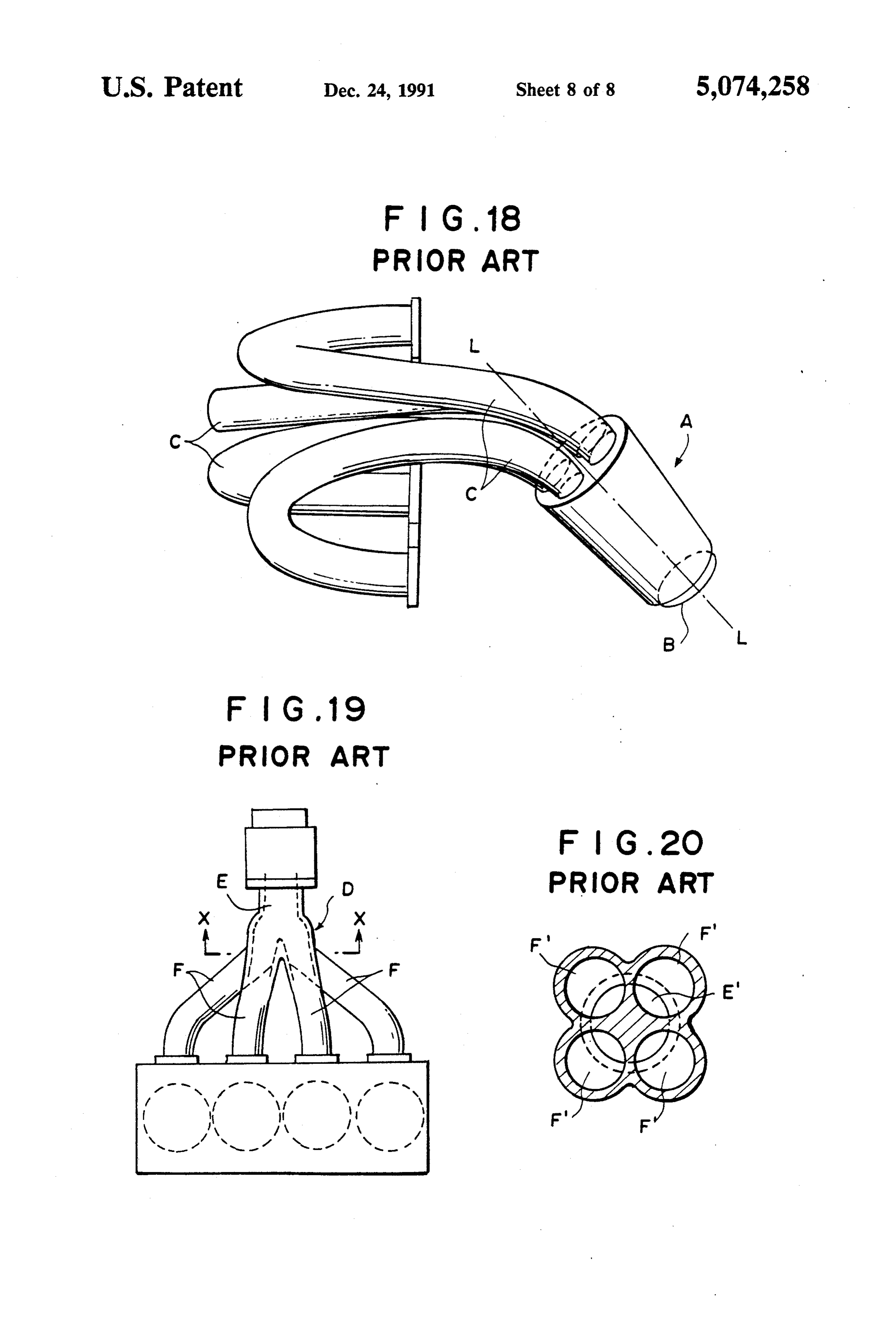
chamber with the atmosphere. In the intake system disclosed in Japanese Unexam 2. Description of the Prior Art
Recently, in an engine for a vehicle, it has been pro shownUtility
posed to increase the charging efficiency by the use of stream side intake19passage in FIGS. and 20, the opening E' of the up kinetic effect of intake air in the intake system. In such D uniformly overlap withEthe into the integrated portion a case, an integrated portion such as a surge tank to crete intake passages F into theopenings
which an upstream side intake passage from an air With this arrangement, it is expected that portion integrated intake
air cleaner is connected is provided in the intake system, introduced into the integrated portion D from the up and discrete intake passages branch off from the inte stream side intake passage E is more uniformly distrib grated portion and communicate with respective cylin ders. In such an intake system, negative pressure wave 25 uted to the discrete intake passages F. generated in the downstream end portion of the discrete However, in the case of the integrated portion A intake passage upon opening of the intake valve is in shown in FIG. 18, the intake resistance cannot be suffi verted into positive pressure wave at the integrated ciently reduced depending on the shape of the inte portion which functions as a space open to the atmo grated portion A, the relation between the areas of the sphere and the engine is supercharged by virtue of the 30 end faces, the distance between the end faces and the positive pressure wave, whereby the charging effi like. Further even if the openings of the discrete intake ciency is improved and the engine output power is passages F and the opening of the upstream side intake increased. passage E are positioned relative to each other in the In the conventional system, as the integrated portion, manner shown in FIG. 20, it is difficult to smoothly there has been wide used a surge tank type integrated 35 distribute intake air so long as intake air is distributed to portion in which the upstream side intake passage is many discrete intake passages from a single upstream connected to one end face of the integrated portion or side intake passage at one time.
the center of one side face of the same, and the discrete intake passages are connected to the side faces of the SUMMARY OF THE INVENTION same. In such an integrated portion, the distances be In view of the foregoing observations and descrip tween the junction of the upstream side intake passage tion, the primary object of the present invention is to to the integrated portion and the junctions of the re provide an intake system having an integrated portion spective discrete intake passages to the integrated por in which the intake resistance is more effectively re tion inherently differ from each other and/or the duced and the charging efficiency is further improved, lengths of the respective discrete intake passages inher 45 ently differ from each other. Accordingly, distribution thereby improving engine output power performance. In accordance with the invention defined in claim 1 of intake air to the respective cylinders cannot be uni (will be referred to as "the first invention'), there is form, and the kinetic effect of intake air cannot uni provided an intake system for a multiple-cylinder en formly act on the respective cylinders. Further, since gine comprising a plurality of discrete intake passages the flow path of intake air from the junction of the 50 which are substantially equal to each other in length upstream side intake passage to the junction of each and are connected to the respective cylinders at their discrete intake passage makes a sharp bend, intake resis downstream ends, an integrated chamber into which the tance of intake air increases.
In order to overcome these problems, there have upstream ends of the discrete intake passages are been proposed various intake systems. 55 merged, and an upstream side intake passage which For example, the intake system disclosed in Japanese communicates the integrated chamber with the atmo Unexamined Utility Model Publication No. sphere, the integrated chamber having an upstream side 60(1985)-88062 has an integrated portion A as shown in end face and a downstream side end face, the cross-sec FIG. 18. The integrated portion A is substantially a tional area of the integrated chamber increasing from truncated cone in shape. The upstream side intake pas the upstream side end face to the downstream side end sage is connected to the end face of the integrated por face, the upstream side intake passage having opening tion having a smaller diameter, and the discrete intake into the integrated portion in the upstream side end passages C are connected to the end face of the same face, and the discrete intake passages respectively hav having a larger diameter. B denotes the opening of the ing openings into the integrated chamber in the down upstream side intake passage into the integrated portion 65 stream side end face, characterized in that formulae A. The openings of the discrete intake passages C are arranged in the larger diameter end face symmetrically Sox 0.25 x SN about axis L-L passing through the center of the open
Page 11
-continued downstream side end, the branch intake passages of the downstream side end portion being smaller than the
H/ N S > 0.7 X (S/So) discrete intake passages in number and the openings of the branch passages into the first integrated chamber are satisfied wherein So and S1 respectively represent uniformly overlap with the openings of the discrete the area of the upstream side and downstream side end intake passages into the second integrated chamber. faces of the integrated chamber, SN represents the sum When the area of the upstream side and downstream of the areas of the openings of the discrete intake pas side end faces of the integrated chamber So and S1, the sages into the integrated chamber, and H represents the sum of the areas of the openings of the discrete intake distance between the upstream side and downstrean O passages into the integrated chamber SN and the dis side end faces of the integrated chamber. tance H between the upstream side and downstream In accordance with the invention defined in claim 2 side end faces of the integrated chamber satisfy the (will be referred to as "the second invention'), there is aforesaid provided an intake system for a multiple-cylinder en the charging formulae, the intake resistance is reduced and gine comprising a plurality of discrete intake passages performance are
efficiency and the engine output power which are substantially equal to each other in length has been empirically substantially improved. The aforesaid and are connected to the respective cylinders at their that the engine output determined and it has been found downstream ends, an integrated chamber into which the when the aforesaid formulae power substantially increases upstream ends of the discrete intake passages are are satisfied. merged, and an upstream side intake passage which 20 Further when the intake passage is divided into the communicates the integrated chamber with the atrino discrete intake passages in a plurality of stages as in the sphere, the integrated chamber having an upstream side second invention, intake air can be more smoothly and end face and a downstream side end face, the cross-sec more uniformly distributed to the cylinders and the tional area of the integrated chamber increasing from intake resistance is more reduced than when the intake the upstream side end face to the downstream side end 25 passage is divided into the discrete intake passages in a face, the upstream side intake passage having opening single stage.
into the integrated chamber in the upstream side end When the openings of the branch passages into the face, and the discrete intake passages respectively hav first integrated chamber uniformly overlap with the ing openings into the integrated chamber in the down openings of the discrete intake passages into the second stream side end face, characterized in that said upstream 30 integrated chamber as in the third invention, intake air side intake passage comprises a downstream side end can be more uniformly distributed to the discrete intake portion including a plurality of branch passages which passages.
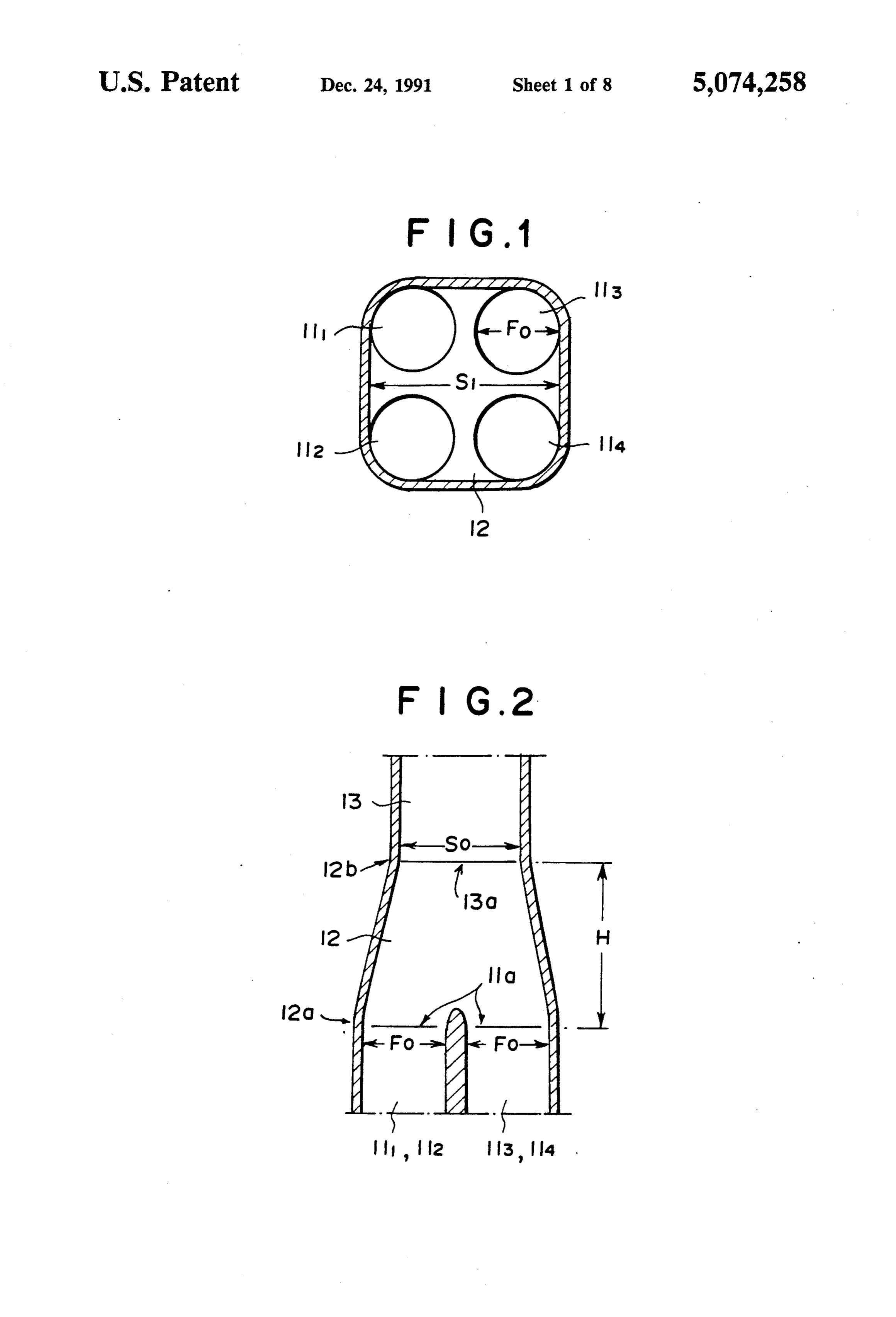
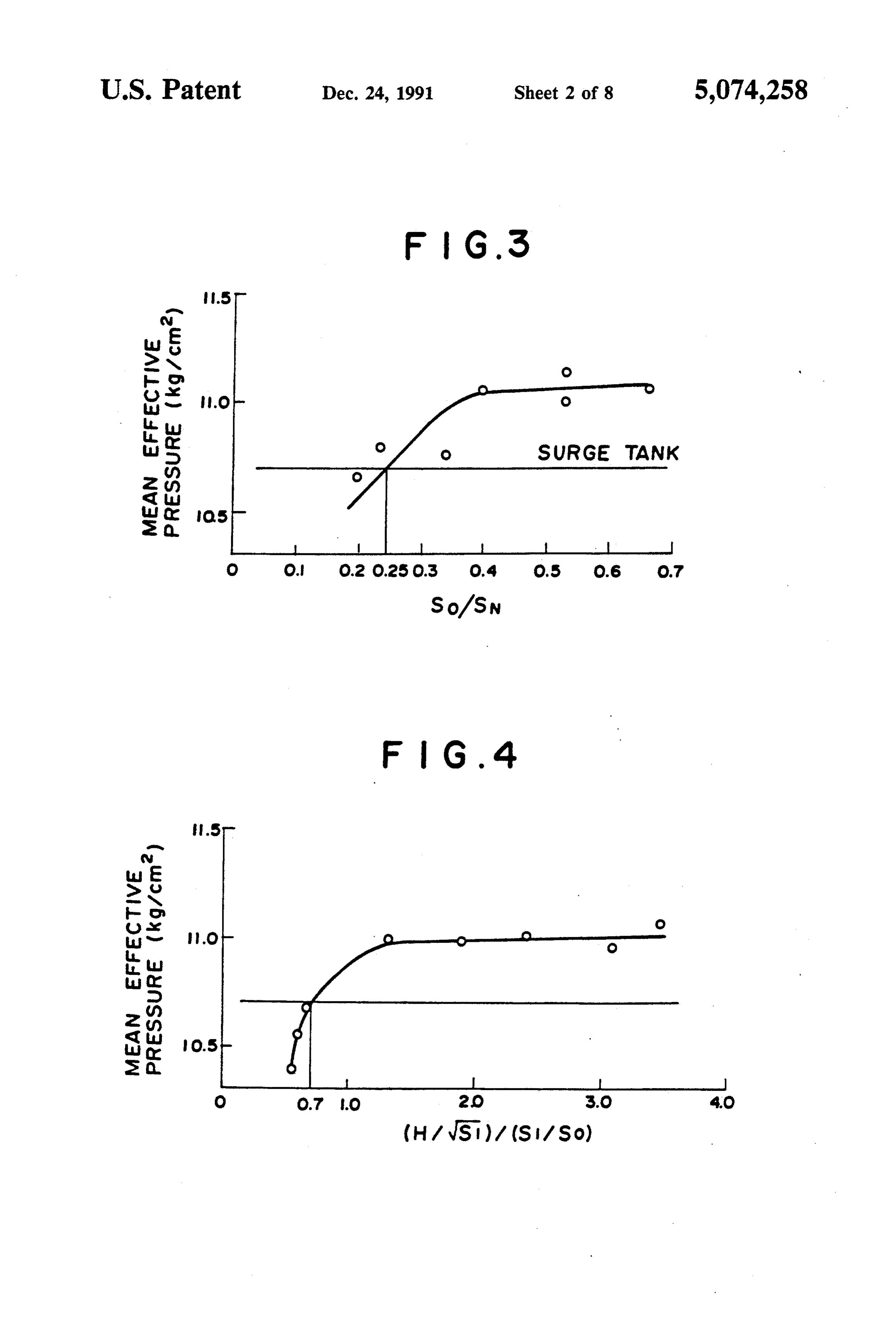
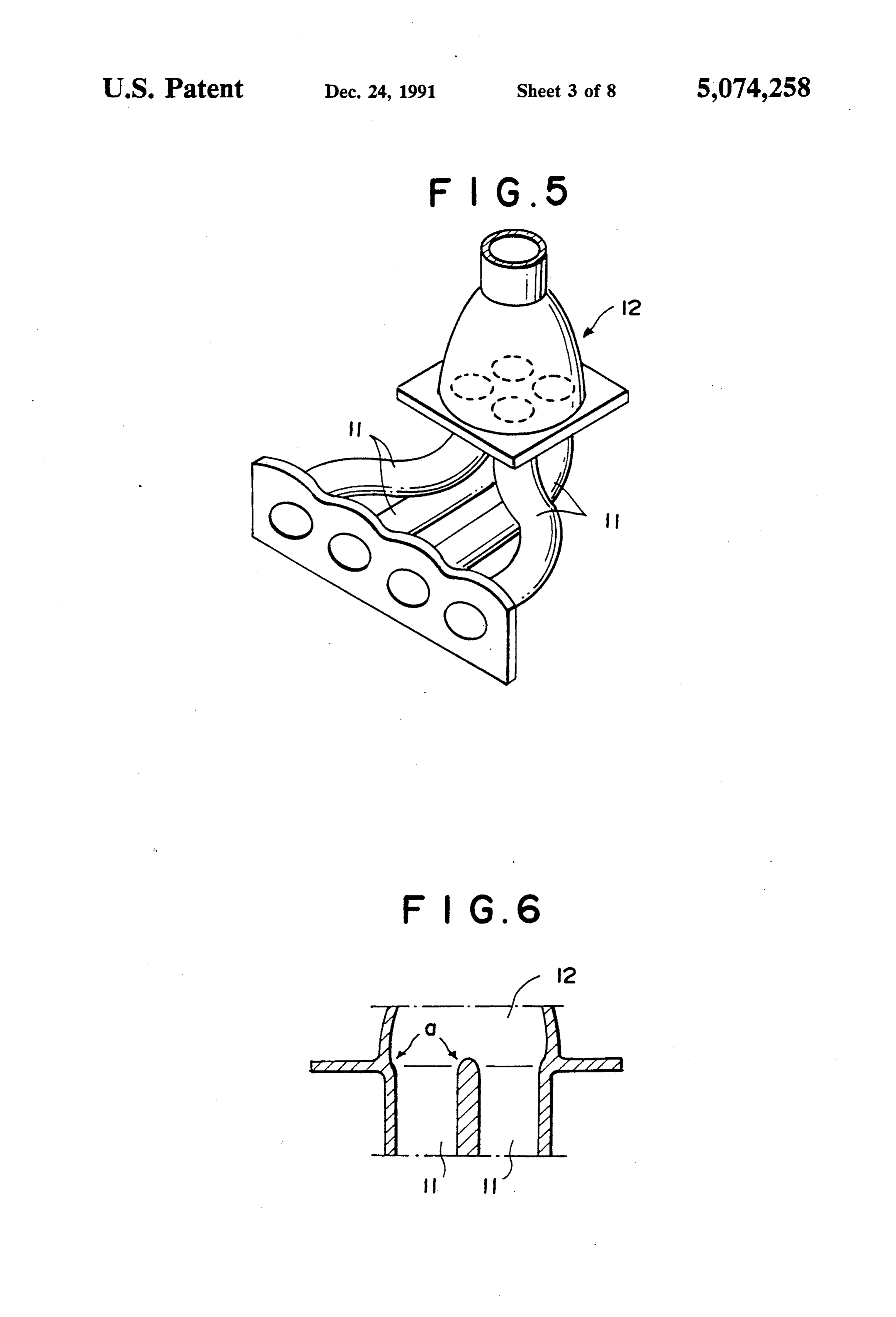
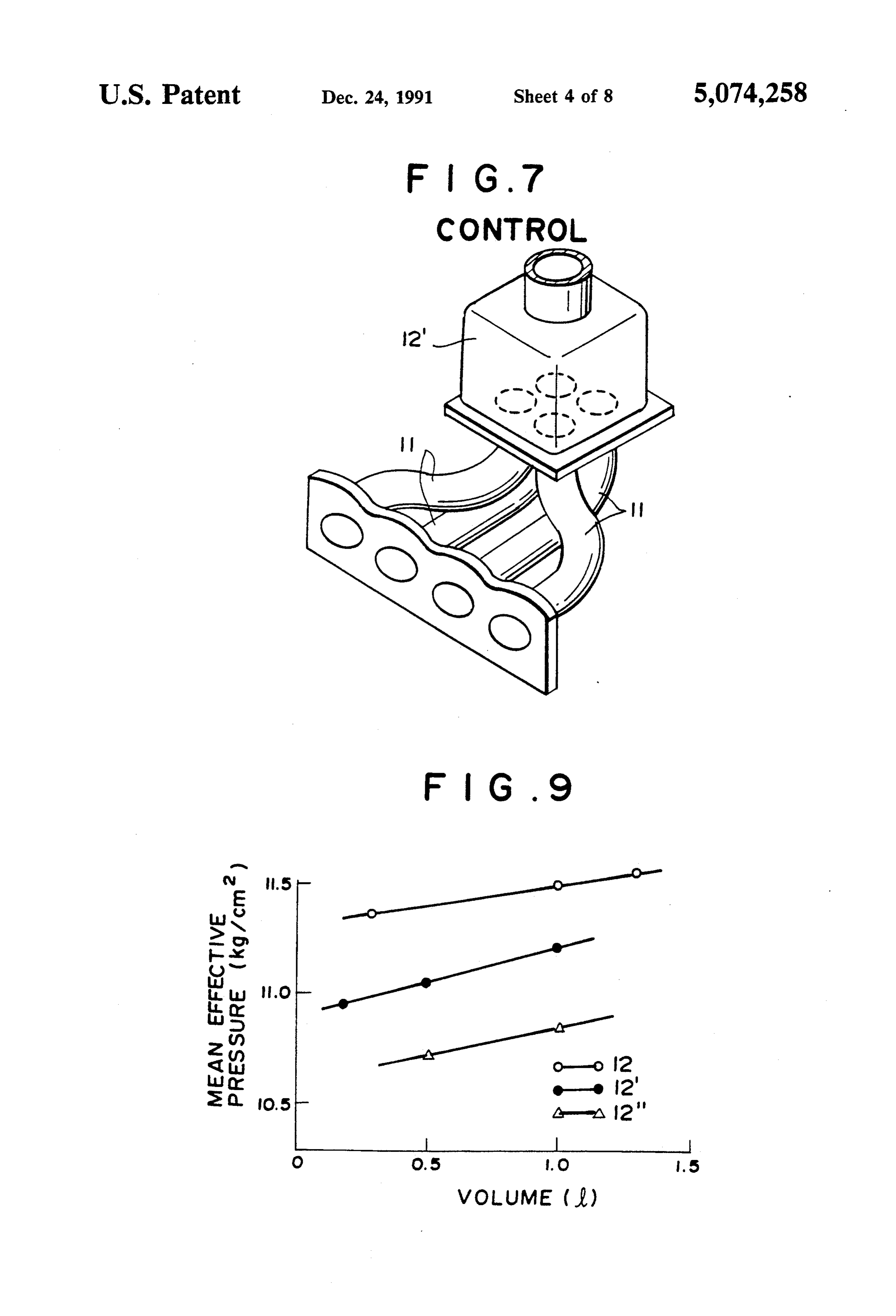
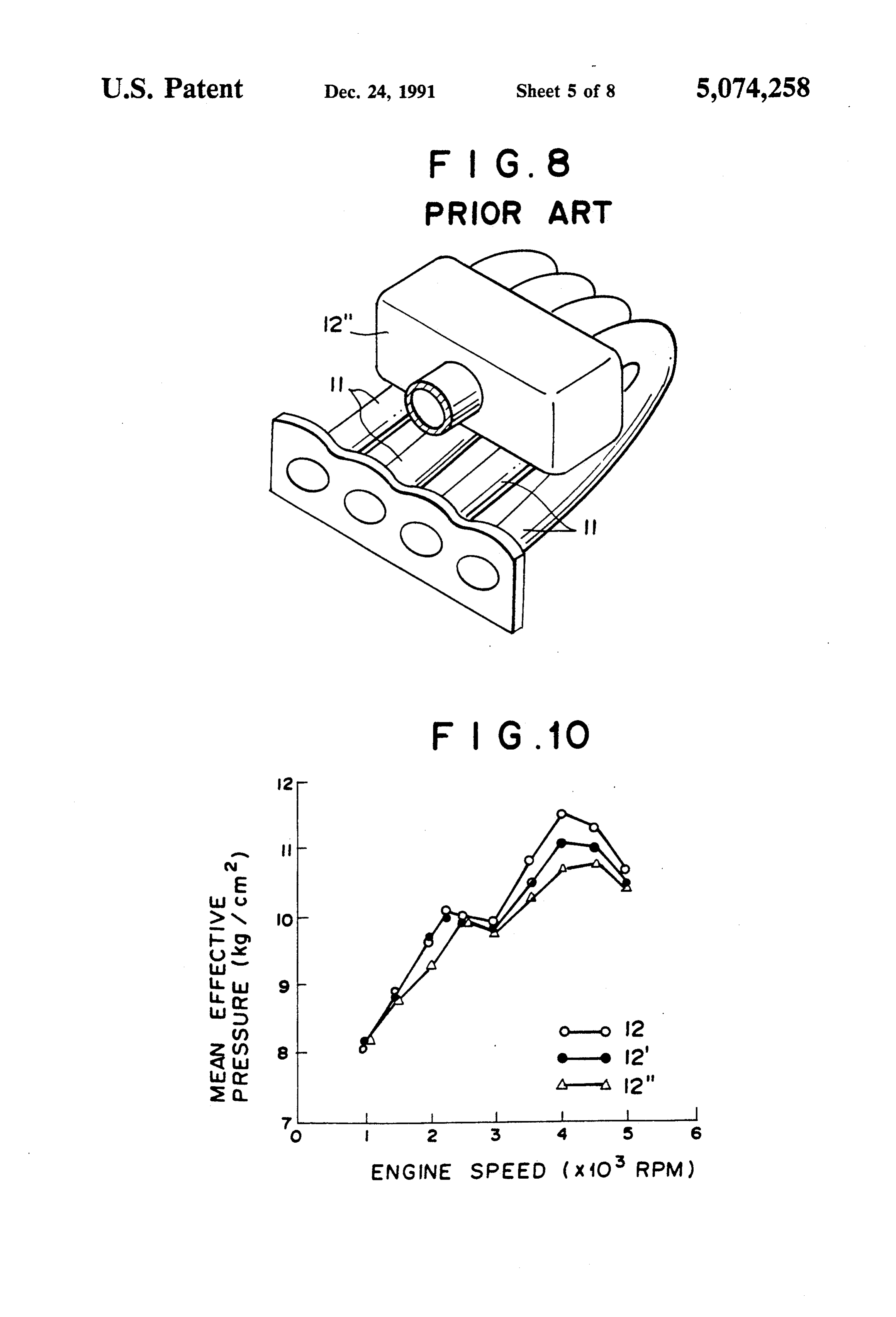
are connected to the integrated chamber at their down BRIEF DESCRIPTION OF THE DRAWINGS stream side end and are merged into a second integrated chamber at their upstream side ends, and an upstream 35 FIG. 1 is a horizontal cross-sectional view showing side end portion which opens to the atmosphere at its an intake system in accordance with an embodiment of upstream side end and connected to the second inte the first invention, grated chamber at its downstream side end, the branch FIG. 2 is a vertical cross-sectional view of the intake intake passages of the downstream side end portion system, being Smaller than the discrete intake passages in num FIGS. 3 and 4 are graphs showing the result of exper ber. inents on the basis of which the first invention was In accordance with the invention defined in claim 3 made, (will be referred to as "the third invention'), there is provided an intake system for a multiple-cylinder en temFIG. 5 is a perspective view showing an intake sys in accordance with an embodiment of the first in gine comprising a plurality of discrete intake passages 45 which are substantially equal to each other in length vention,
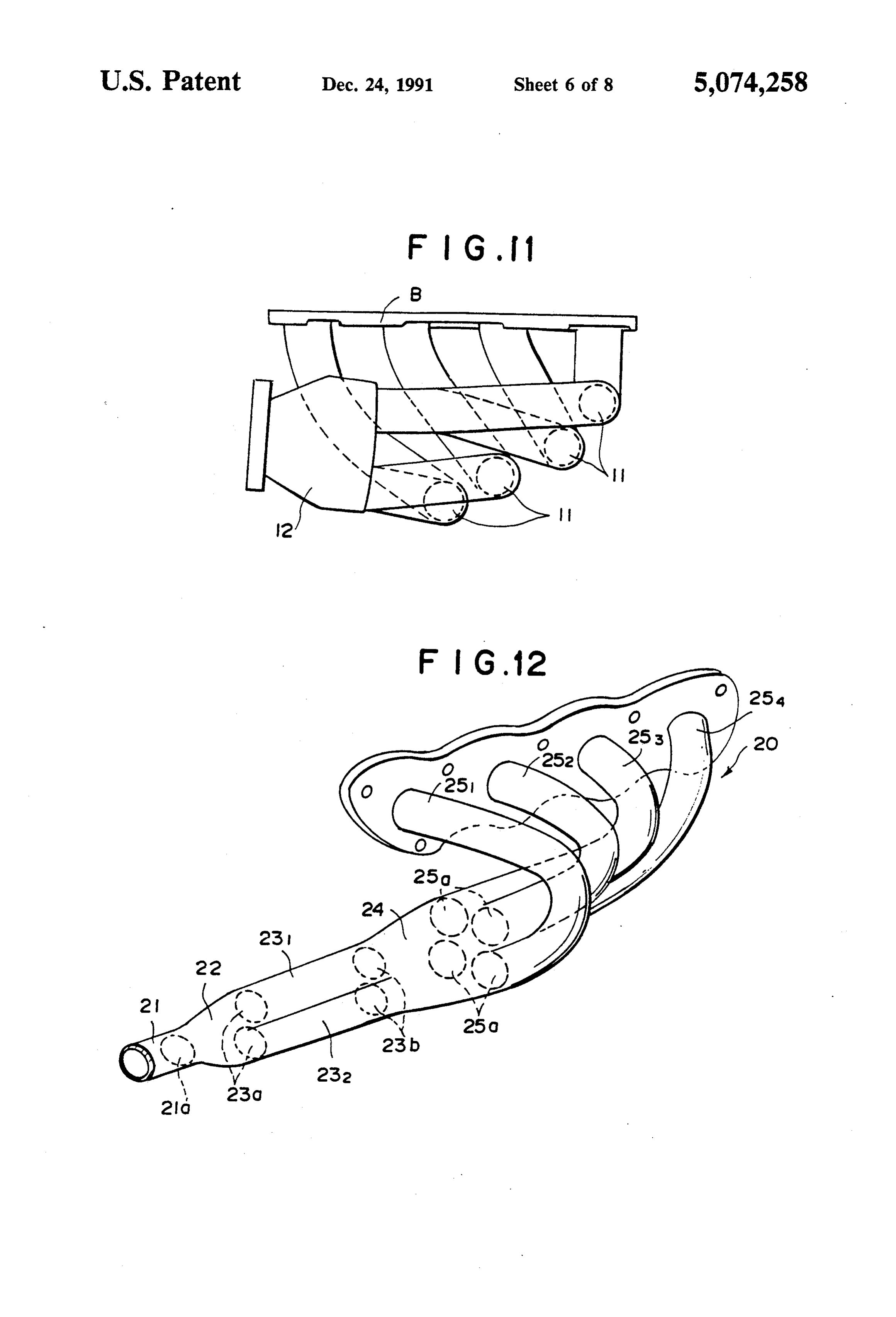
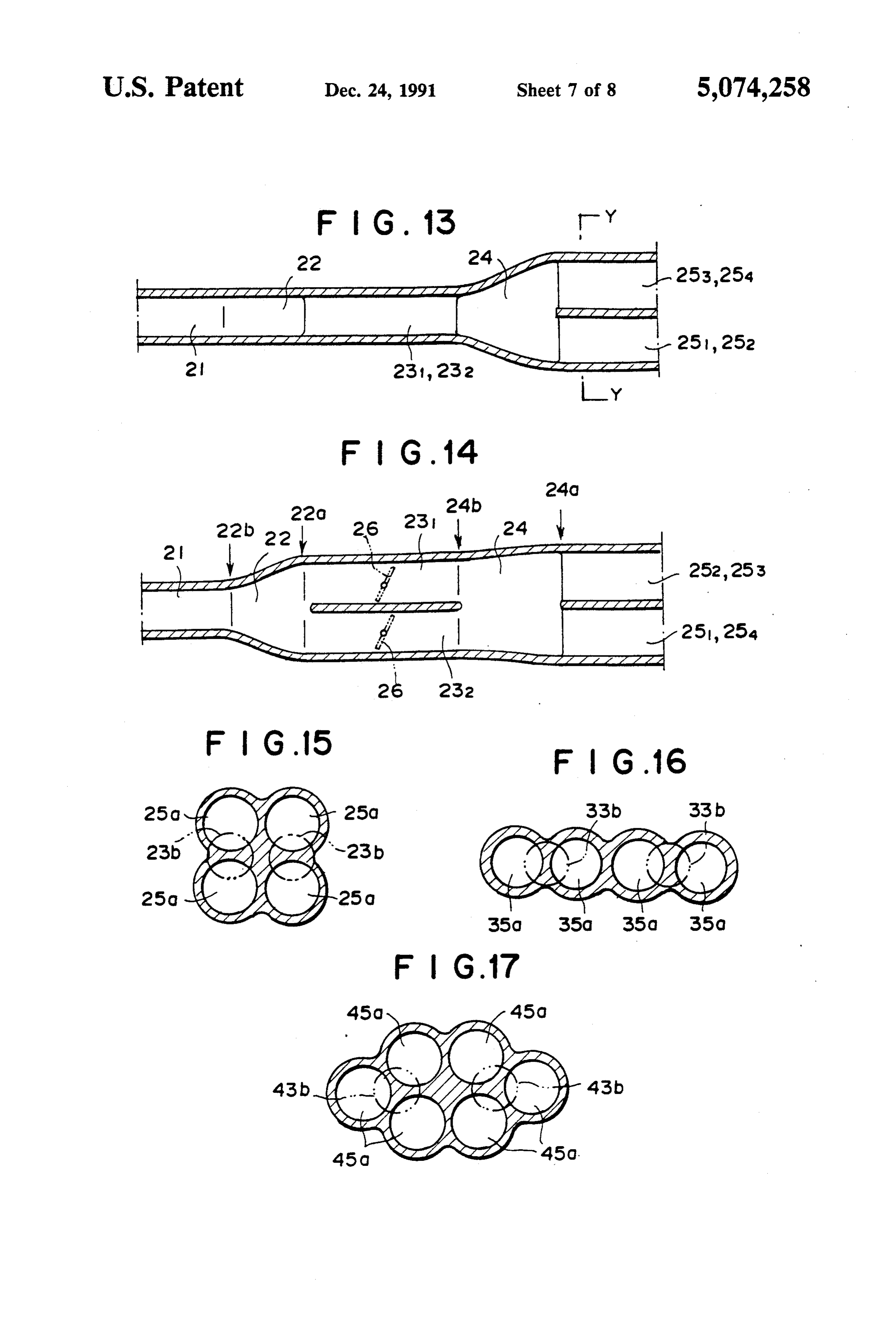
FIG. 6 is a cross-sectional view of the intake system, and are connected to the respective cylinders at their FIG. 7 is a perspective view showing a control intake downstream ends, a first integrated chamber into which system, the upstream ends of the discrete intake passages are merged, and an upstream side intake passage which SO tenFIG. 8 is a perspective view showing an intake sys provided with a surge tank type integrated cham communicates the first integrated chamber with the ber, atmosphere, the first integrated chamber having an FIGS. 9 and 10 are graphs showing the result of upstream side end face and a downstream side end face, experiments which were effected in order to prove the the cross-sectional area of the first integrated chamber effect increasing from the upstream side end face to the down 55 of the first invention, stream side end face, the upstream side intake passage FIG. 11 is a plan view showing a modification of the having opening into the first integrated chamber in the intake system shown in FIG. 7, upstream side end face, and the discrete intake passages FIG. 12 is a perspective view showing an intake sys respectively having openings into the first integrated ten in accordance with an embodiment of the second or chamber in the downstream side end face, characterized 60 third invention, in that said upstream side intake passage comprises a FIG. 13 is a horizontal cross-sectional view of a part downstream side end portion including a plurality of of the intake system shown in FIG. 12, branch passages which are connected to the first inte FIG. 14 is a vertical cross-sectional view of a part of grated chamber at their downstream side end and are the intake system shown in FIG. 12, merged into a second integrated chamber at their up 65 FIG. 15 is a cross-sectional view taken along line stream side ends, and an upstream side end portion Y-Y in FIG. 13, which opens to the atmosphere at its upstream side end FIGS. 16 and 17 are views similar to FIG. 15 but for and connected to the second integrated chamber at its illustrating other embodiments,
Page 12
FIG. 18 is a perspective view showing an intake sys than that in the intake system using the surge tank type tem in accordance with a prior art, integrated chamber when the value (H/VS)/(S1/So) is FIG. 19 is a plan view showing an intake system in larger than 0.7 as shown in FIG. 3. That is, it is neces accordance with another prior art, and sary that the distance H between the upstream side and FIG. 20 is a cross-sectional view taken along line 5 downstream side end faces 12b and 12a of the integrated X-X in FIG. 9. chamber 12 is increased as the value (S1/So) increases in DESCRIPTION OF THE PREFERRED order to effectively reduce the intake resistance and EMBODIMENT increase the engine output power, and when the value (H/VS) is not smaller than 0.7 times the value (S1/So),
The intake system in accordance with an embodiment O the engine output power can be improved as compared of the first invention shown in FIGS. 1 and 2 is substan with the intake system using the surge tank type inte tially the same in structure as those shown in FIGS. 18 grated chamber.
and 19, and has four discrete intake passages 111 to 114 FIGS. 5 and 6 shows an intake system in accordance which are connected to respective cylinders (not with an embodiment of the first invention. The intake shown). The upstream ends of the discrete intake pas 15 system has an integrated chamber 12 the cross-sectional sages 111 to 114 are merged into an integrated chamber area of which smoothly increase from the upstream side 12 and an upstream side intake passage 13 is connected end face to the downstream side end face. Four discrete to the integrated chamber 12 at its downstream end. An intake passages 11 open in the downstream side end face air cleaner (not shown) is mounted on the upstream end of the integrated chamber 12, and the inner edge a of the of the upstream side intake passage 13. 20
The upstream ends of the discrete intake passages 111 upstream end of each discrete intake passages 11 is to 114 open (openings 11a) into the integrated chamber rounded. FIG. 7 shows a control intake system pro 12 in the downstream side end face 12a thereof which is vided with an integrated chamber 12 the cross-sec shaped to circumscribe the openings 11a, and the down tional area of which is constant from the upstream side stream end of the upstream side intake passage 13 opens 25 end face to the downstream side end face. In the case of (openings 13a) into the integrated chamber 12 in the the control intake system, the inner edge of the up upstream side end face 12b thereof. The cross-sectional stream end of each discrete intake passages 11 is not area of the integrated chamber 12 smoothly increases rounded. FIG. 8 shows an intake system provided with from the upstream side end face 12b to the downstream a conventional surge tank type integrated chamber 12'. side end face 12a. The areas So and S1 of the upstream 30 In all the intake systems shown in FIGS. 5 to 8, the side and downstream side end faces 12b and 12a of the tuning engine speed of inertia supercharging is set to integrated chamber 12, the area Fo of the opening 11a 4000 rpm, and the discrete intake passages are all 450 of each discrete intake passage 11 into the integrated mm in length.
chamber 12 and the distance H between the upstream In these intake systems respectively having the inte side and downstream side end faces 12b and 12a of the 35 grated chambers 12, 12" and 12", change in mean effec integrated chamber 12 are determined to satisfy the tive pressure at the tuning engine speed with change of following formulae wherein SN represents the sum of the volume of the integrated chamber was measured. the areas Fo of the openings 11a (SN= Fox4). The result was as shown in FIG. 9. Further change in mean effective pressure with change of the engine speed
So 0.25 X SN (1) 40 was measured while the volume of the integrated cham ber was fixed to 1.0 l. The result was as shown in FIG.
As can be understood from FIGS. 9 and 10, the en gine output power performance was worst in the engine
These formulae were empirically determined. Mean provided with the intake system having the surge tank effective pressure at a tuning engine speed of inertia 45 type integrated chamber 12", and was best in the engine effect supercharging was measured for various values of provided with the intake system in accordance with the the area ratio SO/SN, and it has been found that the first invention.
mean effective pressure becomes higher than that in the most effectivelyThis means that the intake resistance is reduced in the integrated chamber 12 intake system using the surge tank type integrated in accordance with chamber when the area ratio So/SN is not larger than SO In order to more the first invention. compactly arrange the engine (in 0.25 as shown in FIG. 3. That is, when the area Soof the upstream side end face 12b (the area of the opening 13a clusive of the intake system) and reduce the height of of the upstream side intake passage 13 into the inte the engine, it is preferred that the integrated chamber 12 grated chamber 12) is smaller than 25% Of the sum SN be disposed on one side of the engine body and extend of the areas Fo of the openings 11a of the discrete intake 55 in the direction of the cylinder row as shown in FIG. passages 11 to 114, the change in the cross-sectional 11.Now In FIG. 11, B denotes the engine body. an embodiment of the second and third inven area of the path of intake air from the upstream side intake passage 13 to the integrated chamber 12 or to the tions will be described with reference to FIGS. 12 to 15, discrete intake passages 111 to 114 is too large and the hereinbelow. In FIGS. 12 to 15, an intake manifold 20 intake resistance cannot be sufficiently reduced. Ac comprises a first upstream side intake passage 21 which cordingly, it is necessary that the area So of the up opens to the atmosphere through an air cleaner (not stream side end face 12b is set to satisfy the formula (1) shown) mounted on the upstream end thereof, a first in order to effectively reduce the intake resistance and integrated chamber 22 to which the downstream end of increase the engine output power. the first upstream side intake passage 21 is connected, a Further, mean effective pressure at a tuning engine 65 pair of second upstream side intake passages 231 and 232 speed of inertia effect supercharging was measured for which extend downstream from the first integrated various values of (H/VS)/(S1/So), and it has been chamber 22, a second integrated chamber 24 to which found that the mean effective pressure becomes higher the downstream ends of the second upstream side intake
Page 13
passages 231 and 232 are connected, and four discrete second integrated chamber in the case of the embodi intake passages 251 to 254 which extend downstream ment described above).
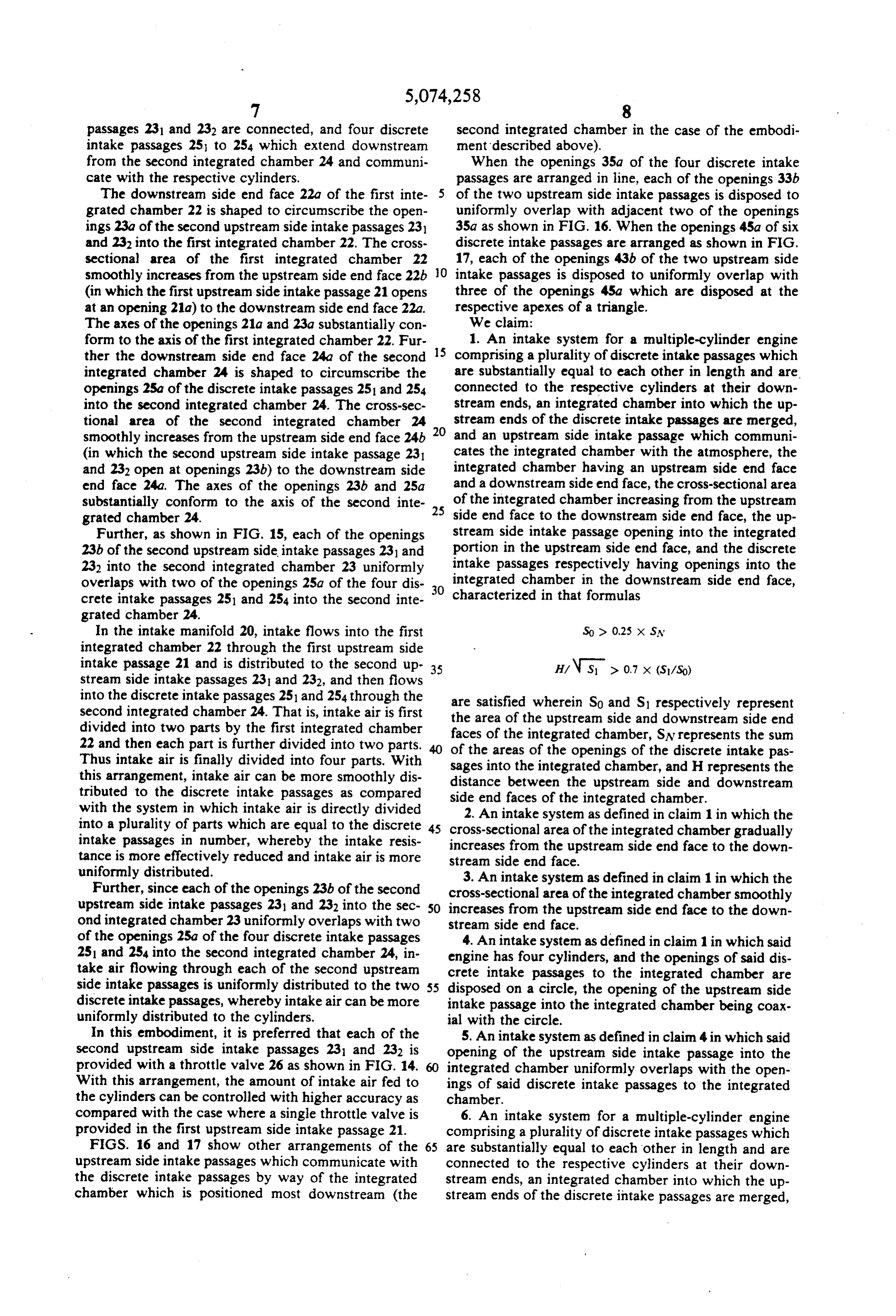
from the second integrated chamber 24 and communi When the openings 35a of the four discrete intake cate with the respective cylinders. passages are arranged in line, each of the openings 33b The downstream side end face 22a of the first inte of the two upstream side intake passages is disposed to grated chamber 22 is shaped to circumscribe the open uniformly overlap with adjacent two of the openings ings 23a of the second upstream side intake passages 231 35a as shown in FIG. 16. When the openings 45a of six and 232 into the first integrated chamber 22. The cross discrete intake passages are arranged as shown in FIG. sectional area of the first integrated chamber 22 17, each of the openings 43b of the two upstream side smoothly increases from the upstream side end face 22b O intake passages is disposed to uniformly overlap with (in which the first upstream side intake passage 21 opens three of the openings 45a which are disposed at the at an opening 21a) to the downstream side end face 22a. respective apexes of a triangle.
The axes of the openings 21a and 23a substantially con We claim:
form to the axis of the first integrated chamber 22. Fur 15 1. An intake system for a multiple-cylinder engine ther the downstream side end face 24a of the second comprising a plurality of discrete intake passages which integrated chamber 24 is shaped to circumscribe the are substantially equal to each other in length and are. openings 2.5a of the discrete intake passages 251 and 254 connected to the respective cylinders at their down into the second integrated chamber 24. The cross-sec stream ends, an integrated chamber into which the up tional area of the second integrated chamber 24 stream ends of the discrete intake passages are merged, smoothly increases from the upstream side end face 24b 20 and an upstream side intake passage which communi (in which the second upstream side intake passage 231 cates the integrated chamber with the atmosphere, the and 232 open at openings 23b) to the downstream side integrated chamber having an upstream side end face end face 24a. The axes of the openings 23b and 25a and a downstream side end face, the cross-sectional area substantially conform to the axis of the second inte 25 of the integrated chamber increasing from the upstream grated chamber 24. side end face to the downstream side end face, the up Further, as shown in FIG. 15, each of the openings stream side intake passage opening into the integrated 23b of the second upstream side intake passages 231 and portion in the upstream side end face, and the discrete 232 into the second integrated chamber 23 uniformly intake passages respectively having openings into the integrated chamber in the downstream side end face, overlaps with two of the openings 25a of the four dis 30 characterized crete intake passages 251 and 254 into the second inte in that formulas grated chamber 24.
In the intake manifold 20, intake flows into the first So d 0.25 x SN integrated chamber 22 through the first upstream side intake passage 21 and is distributed to the second up 35 H/ N S > 0.7 x (S/SO) stream side intake passages 231 and 232, and then flows into the discrete intake passages 251 and 254 through the are satisfied wherein So and S1 respectively represent second integrated chamber 24. That is, intake air is first the divided into two parts by the first integrated chamber facesarea of the upstream side and downstream side end 22 and then each part is further divided into two parts. of the areas integrated of the of the chamber, SN represents the sum openings of the discrete intake pas
Thus intake air is finally divided into four parts. With sages into the integrated chamber, and H represents the this arrangement, intake air can be more smoothly dis distance between the upstream side and downstream tributed to the discrete intake passages as compared side end faces of the integrated chamber. with the system in which intake air is directly divided 2. An intake system as defined in claim 1 in which the into a plurality of parts which are equal to the discrete 45 cross-sectional intake passages in number, whereby the intake resis increases from area the of the integrated chamber gradually upstream side end face to the down tance is more effectively reduced and intake air is more stream side end face.
uniformly distributed. 3. An intake system as defined in claim 1 in which the Further, since each of the openings 23b of the second cross-sectional area of the integrated chamber smoothly upstream side intake passages 231 and 232 into the sec SO increases from the upstream side end face to the down ond integrated chamber 23 uniformly overlaps with two stream side end face.
of the openings 25a of the four discrete intake passages 4. An intake system as defined in claim 1 in which said 251 and 254 into the second integrated chamber 24, in engine has four cylinders, and the openings of said dis take air flowing through each of the second upstream crete intake passages to the integrated chamber are side intake passages is uniformly distributed to the two 55 disposed on a circle, the opening of the upstream side discrete intake passages, whereby intake air can be more intake passage into the integrated chamber being coax uniformly distributed to the cylinders. ial with the circle.
In this embodiment, it is preferred that each of the 5. An intake system as defined in claim 4 in which said second upstream side intake passages 231 and 232 is opening of the upstream side intake passage into the provided with a throttle valve 26 as shown in FIG. 14. integrated chamber uniformly overlaps with the open With this arrangement, the amount of intake air fed to ings of said discrete intake passages to the integrated the cylinders can be controlled with higher accuracy aschamber.
compared with the case where a single throttle valve is 6. An intake system for a multiple-cylinder engine provided in the first upstream side intake passage 21. comprising a plurality of discrete intake passages which FIGS. 16 and 17 show other arrangements of the 65 are substantially equal to each other in length and are upstream side intake passages which communicate with connected to the respective cylinders at their down the discrete intake passages by way of the integrated stream ends, an integrated chamber into which the up chamber which is positioned most downstream (the stream ends of the discrete intake passages are merged,
Page 14
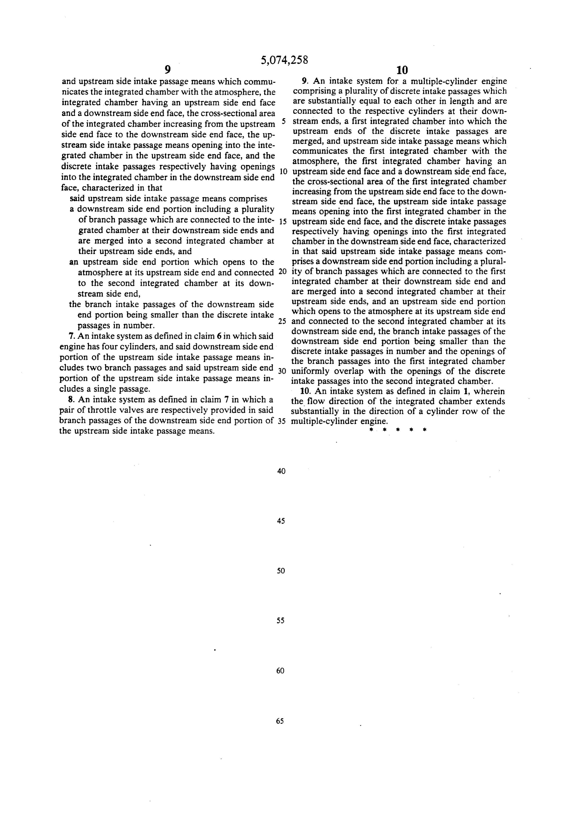
and upstream side intake passage means which commu 9. An intake system for a multiple-cylinder engine nicates the integrated chamber with the atmosphere, the comprising a plurality of discrete intake passages which integrated chamber having an upstream side end face are substantially equal to each other in length and are and a downstream side end face, the cross-sectional area connected to the respective cylinders at their down of the integrated chamber increasing from the upstream 5 stream ends, a first integrated chamber into which the side end face to the downstream side end face, the up upstream ends of the discrete intake passages are stream side intake passage means opening into the inte communicatesupstream merged, and side intake passage means which the first integrated chamber with the grated chamber in the upstream side end face, and the discrete intake passages respectively having openings 10 atmosphere, upstream side the first integrated chamber having an end face and a downstream side end face, into the integrated chamber in the downstream side end the cross-sectional area of the first integrated chamber face, characterized in that increasing from the upstream side end face to the down said upstream side intake passage means comprises stream side end face, the upstream side intake passage a downstream side end portion including a plurality means opening into the first integrated chamber in the of branch passage which are connected to the inte 5 upstream side end face, and the discrete intake passages grated chamber at their downstream side ends and respectively having openings into the first integrated are merged into a second integrated chamber at chamber in the downstream side end face, characterized their upstream side ends, and in that said upstream side intake passage means com an upstream side end portion which opens to the prises a downstream side end portion including a plural atmosphere at its upstream side end and connected 20 ity of branch passages which are connected to the first to the second integrated chamber at its down integrated chamber at their downstream side end and stream side end, are merged into a second integrated chamber at their the branch intake passages of the downstream side which upstream side ends, and an upstream side end portion end portion being smaller than the discrete intake 25 opens to the atmosphere at its upstream side end passages in number. and connected to the second integrated chamber at its downstream side end, the branch intake passages of the 7. An intake system as defined in claim 6 in which said downstream engine has four cylinders, and said downstream side end discrete side end portion being smaller than the intake portion of the upstream side intake passage means in the branch passages passages in number and the openings of cludes two branch passages and said upstream side end 30 uniformly overlap with into the first integrated chamber the openings of the discrete portion of the upstream side intake passage means in intake passages into the second integrated chamber. cludes a single passage. 10. An intake system as defined in claim 1, wherein 8. An intake system as defined in claim 7 in which a the flow direction of the integrated chamber extends pair of throttle valves are respectively provided in said substantially in the direction of a cylinder row of the branch passages of the downstream side end portion of 35 multiple-cylinder engine.
the upstream side intake passage means. k six st t s:
Provenance
- Collection
- Cited prior art
- Original PDF
- patentimages.storage.googleapis.com →
- Filed
- 1990-09-04
- Pages
- 14
- Method
- pdftotext (the PDF's own text layer) + pdftoppm 300dpi page scans
- Source
- Google Patents bibliographic record
- Granted
- 1991-12-24
- Inventors
- Mitsuo Hitomi; Toshihiko Hattori; Masashi Marubara; Mikihito Fujii; Mazda Motor Corp
- Transcribed from
- patentimages.storage.googleapis.com →