patent · US4698765
Ignition timing control system for an automotive engine
6 October 1987
Page 1 — bibliographic record
United States Patent (19) 11) Patent Number: 4,698,765 Abe et al. (45) Date of Patent: Oct. 6, 1987 (54) IGNITION TIMING CONTROL SYSTEM 56) References Cited FOR AN AUTOMOTIVE ENGINE U.S. PATENT DOCUMENTS (75) Inventors: Kunihiro Abe, Higashimurayama; 4,376,428 3/1983 Hata et al. ...................... 364/43.04 Yoshitake Matsumura, Hachiouji; 4,377,996 3/1983 Yamaguchi ......................... 123/417 Takurou Morozumi, Mitaka, all of 4,461,261 7/1984 Isomura et al. ..................... 123/489 Japan 4,508,075 4/1985 Takao et al. .. ... 123/489 4,510,910 4/1985 Ninomiya et al. ... 23/486 73) Assignee: Fuji. Jukogyo Kabushiki Kaisha, 4,644,920 2/1987 Abe et al. ............................ 23/486 Tokyo, Japan
Primary Examiner-Parshotam S. Lall (21) Appl. No.:757,816 Attorney, Agent, or Firm-Martin A. Farber 22 Filed: Jul. 22, 1985 57) ABSTRACT 30 Foreign Application Priority Data A system is provided for updating data stored in a table Jul. 27, 1984 JP Japan ................................ 59-158030 at a steady state of an engine in accordance with a feed back signal of an O2-sensor. When an updated data is 51) Int. Cl." ................................................ F02P 5/14 exceeds a predetermined upper or lower limit value, the 52 U.S. Cl. ................ ... 364/431.04; 123/489 ignition timing of the engine is adjusted. 58) Field of Search...................... 364/431.04, 431.05, 364/431.12; 123/486, 480, 417,489 2 Claims, 11 Drawing Figures
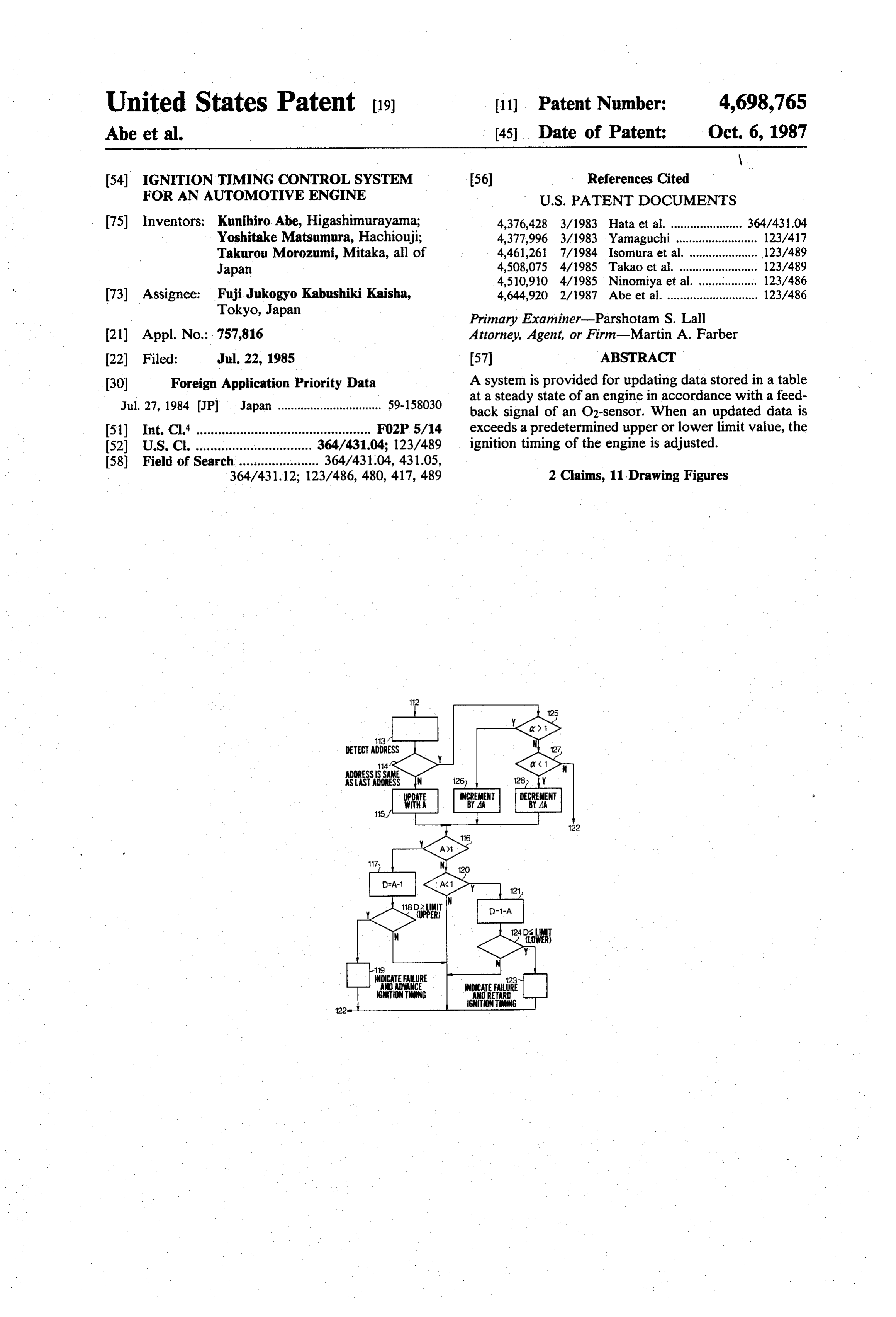
DETECT ADDRESS
ADDRESSISSAME
ASASADRESS
SNTONTING
Page 2
Drawing sheet — no readable text.
Page 3
Drawing sheet — no readable text.
Page 4
Drawing sheet — no readable text.
Page 5
Drawing sheet — no readable text.
Page 6
Drawing sheet — no readable text.
Page 7
Drawing sheet — no readable text.
Page 8
According to the present invention, there is provided
GNTON TIMING CONTROL SYSTEM FOR AN a system for controlling the amount of fuel to be sup AUTOMOTIVE ENGINE plied to an automotive engine by updated data, compris ing, a table storing data, an O2-sensor for detecting
BACKGROUND OF THE INVENTION 5 constituents of exhaust gases of the engine and for pro ducing an output voltage dependent on the concentra
The present invention relates to a system for control tion of the exhaust gases, and means for updating the ling the ignition timing of an automotive engine at the data in the table with a value relative to the output failure of a sensor, and more particularly to an ignition voltage. In the system, the updated data is compared timing control system using a learning control system 10 with predetermined upper and lower limit values. When which is provided for updating data stored in a table for the updated data exceeds controlling the fuel supply in an electronic fuel-injec the ignition timing of thethe upper or lower limit value, engine is adjusted.
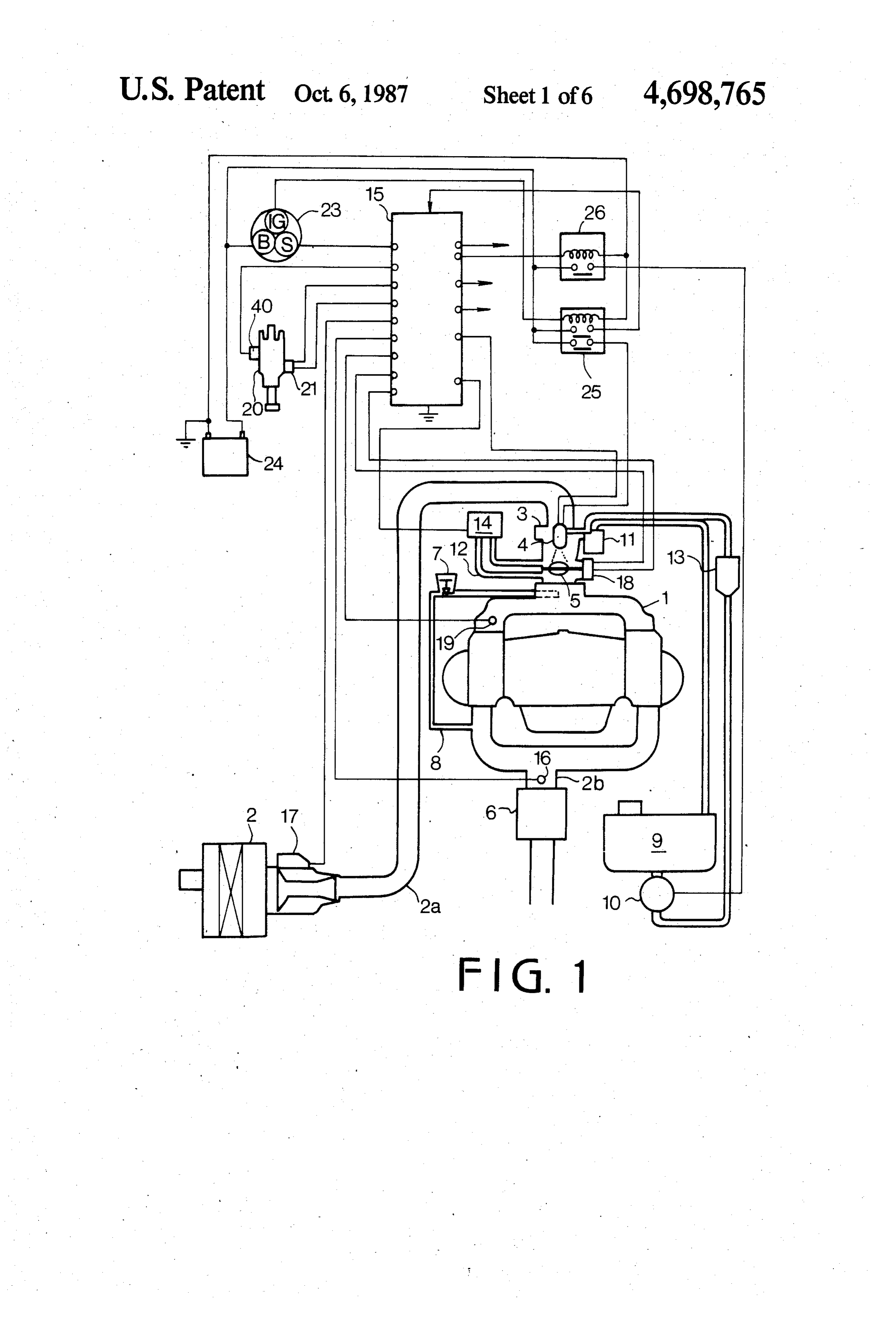
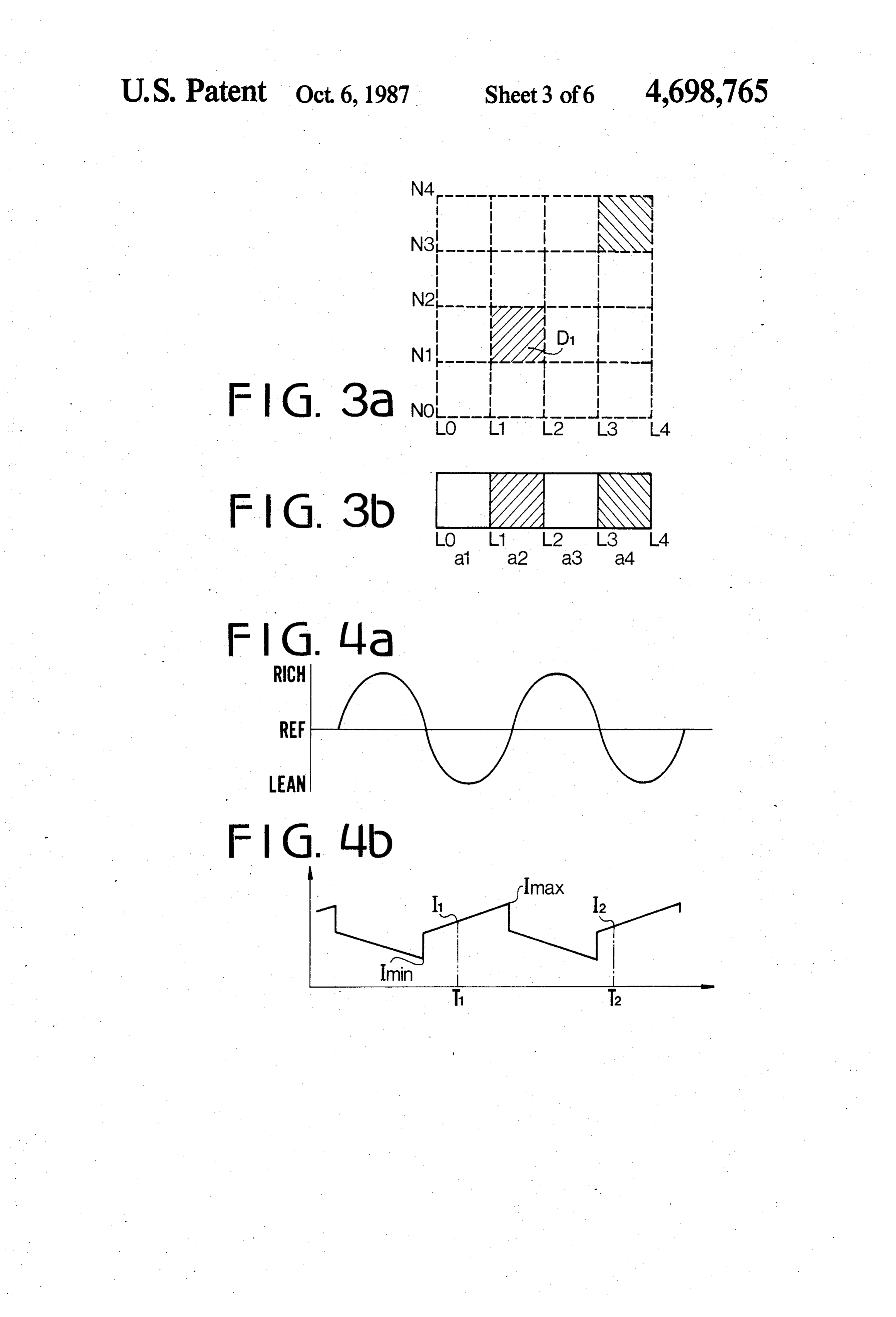
tion system. The other objects and features of this invention will -In one type of electronic fuel-injection control, the be apparently understood from the following descrip amount of fuel to be injected into the engine is deter 15 tion with reference to the accompanying drawings. mined in accordance with engine operating variables such as mass air flow, engine speed and engine load. BRIEF DESCRIPTION OF DRAWINGS The amount of fuel is decided by a fuel injector energi FIG. 1 is a schematic illustration showing a system zation time (injection pulse width). Basic injection pulse for controlling the operation of an internal combustion width (T) can be obtained by the following formula. 20 engine for a motor vehicle;
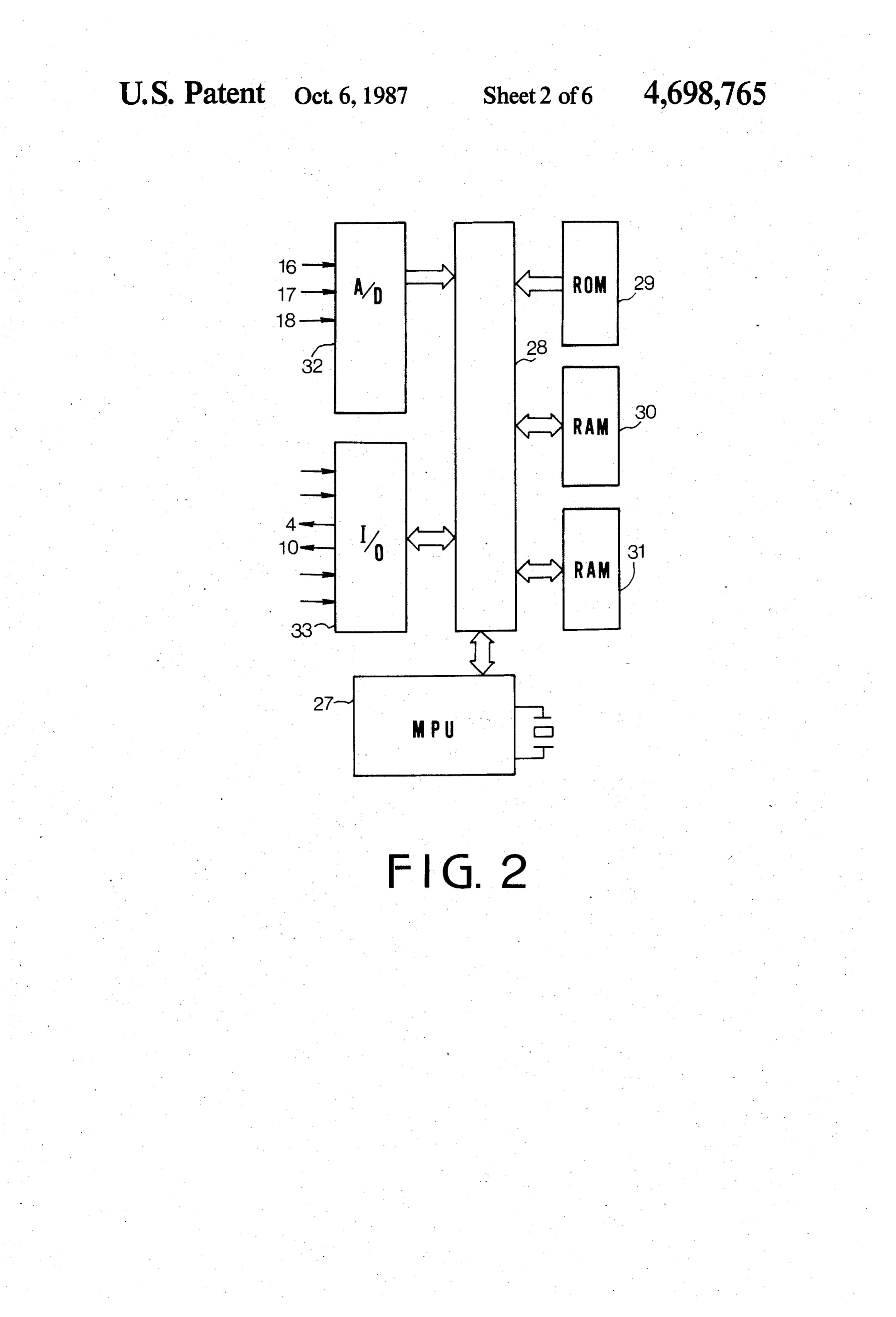
FIG. 2 is a block diagram of a microcomputer system
T=KXQ/N (1) used in a system of the present invention; -- - where Q is mass air flow, N is engine speed, and K is a FIG. 3a is an illustration showing a matrix for detect constant.
ing the steady state of engine operation;
Desired injection pulse width (T) is obtained by 25 FIG. 3b shows a table for learning control coeffici ents;
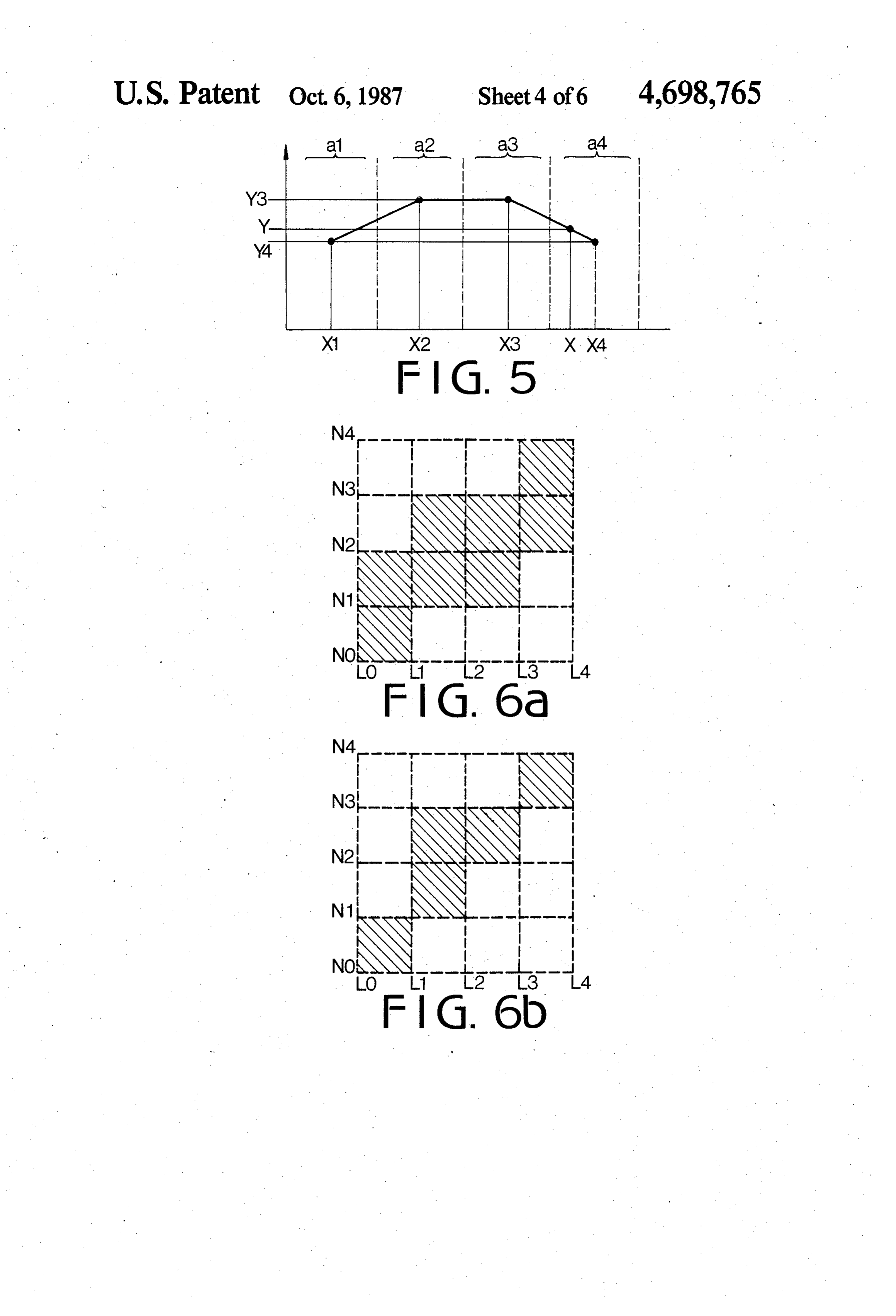
correcting the basic injection pulse (T) with engine FIG. 4a shows the output voltage of an O2-sensor; operating variables. The following is an example of a FIG. 4b shows the output voltage of an integrator; formula for computing the desired injection pulse FIG. 5 shows a linear interpolation for reading the width. 30 table of FIG. 3b
FIGS. 6a and 6b are illustration for explaining proba
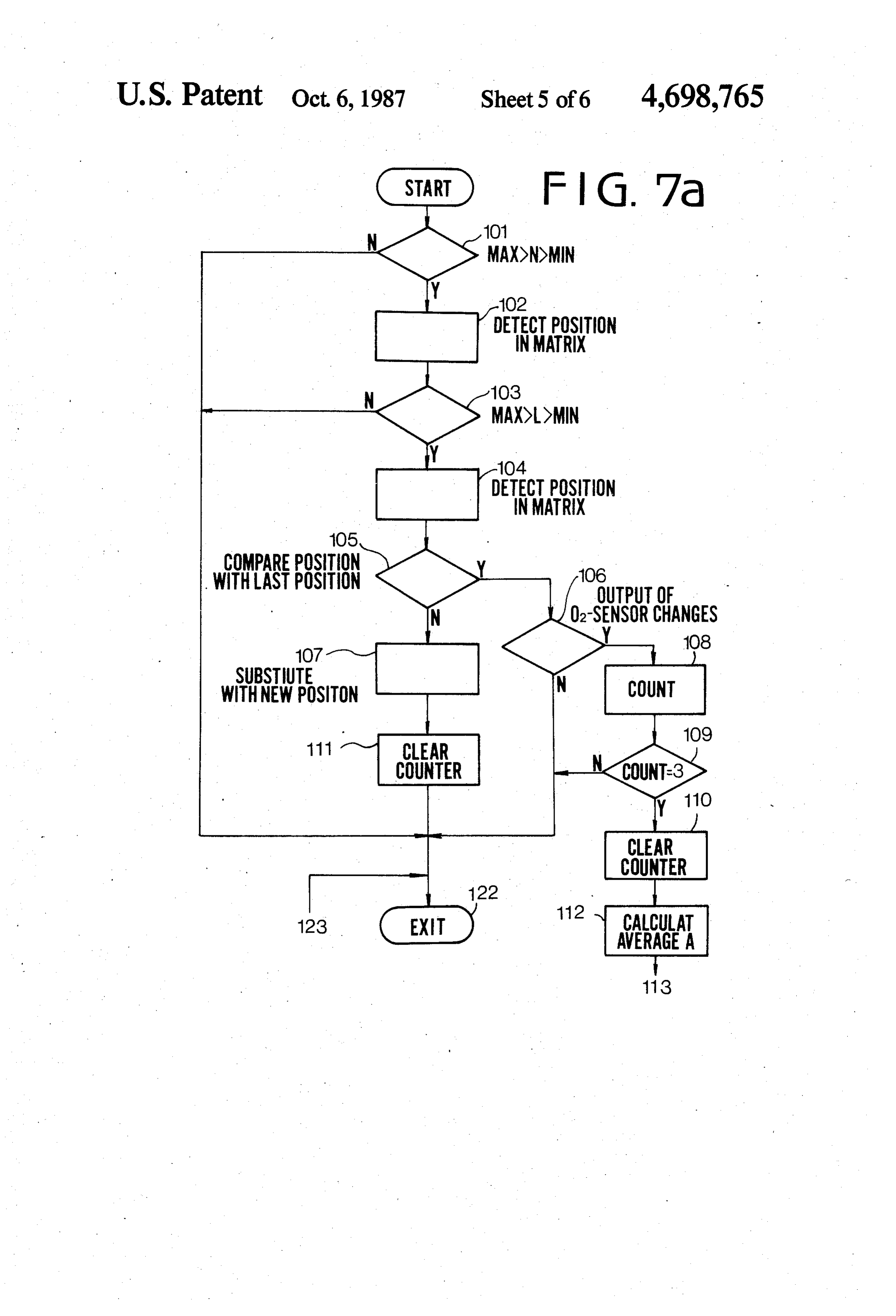
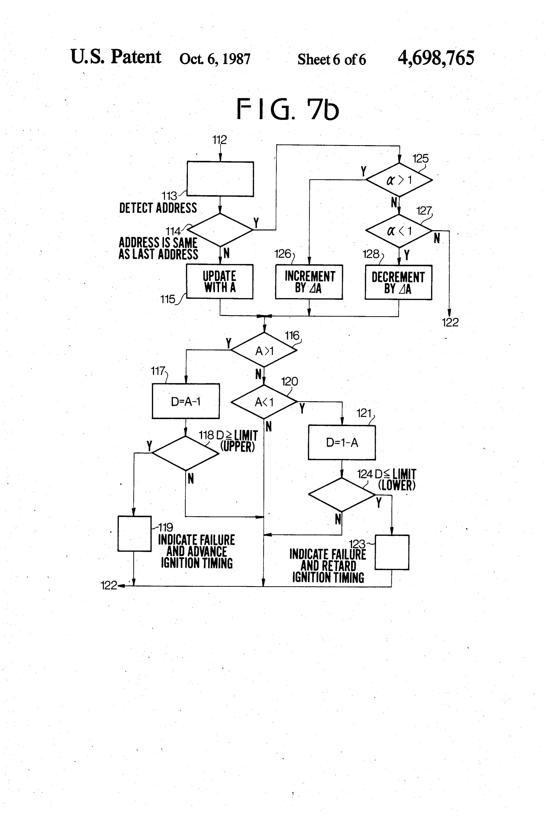
Ti=TX(COEF)xax Ka (2) bility of updating; and where COEF is a coefficient obtained by adding vari FIGS. 7a and 7b are flowcharts showing the opera ous correction or compensation coefficients such as 35 tion in an embodiment of the present invention; coefficients on coolant temperature, full throttle open, DETALED DESCRIPTION OF THE engine load, etc., d is a A correcting coefficient (the PREFERRED EMBODIMENT integral of the feedback signal of an O2-sensor provided Referring to FIG. 1, an internal combustion engine 1 in an exhaust passage), and Kais a correcting coefficient for a motor vehicle is supplied with air through an air by learning (hereinafter called learning control coeffici cleaner 2, intake pipe 2a, and throttle valve 5 in a throt ent). Coefficients, such as coolant temperature coeffici tle body 3, mixing with fuel injected from an injector 4. ent and engine load, are obtained by looking up tables in A three-way catalitic converter 6 and an O2-sensor 16 accordance with sensed informations. The value of the are provided in an exhaust passage 2b. An exhaust gas learning control coefficient Ka is obtained from a Ka recirculation (EGR) valve 7 is provided in an EGR table in accordance with engine load. 45 passage 8 in a well known manner. On the other hand, the ignition timing of the engine is Fuel in a fuel tank 9 is supplied to the injector 4 by a decided also by the mass air flow Q. More particularly, fuel pump 10 through a filter 13 and pressure regulator if the mass air flow Q increases, the amount of fuel 11. A solenoid operated valve 14 is provided in a bypass increases and, at the same time, ignition timing is ad 12 around the throttle valve 5 so as to control engine vanced as increasing of the fuel. Accordingly, if a mass 50 speed at idling operation. A mass air flow meter 17 is air flow meter deteriorates to fail to produce a proper provided on the intake pipe 2a and a throttle position output voltage, the air-fuel ratio of mixture supplied to sensor 18 is provided on the throttle body 3. A coolant the engine deviates from a stoichiometry and improper temperature sensor 19 is mounted on the engine. Output ignition timing is set. For example, if the output voltage signals of the meter 17 and sensors 18 and 19 are applied increases by the failure of the mass air flow meter, the 55 to a microcomputer 15. The microcomputer 15 is also ignition timing is advanced regardless of engine operat applied with a crankangle signal from a crankangle ing conditions. Such improper advancing of timing will sensor 21 mounted on a distributor 20 and a starter occur the knocking of the engine. signal from a starter switch 23 which operates to turn SUMMARY OF THE INVENTION on-off electric current from a battery 24. The system is further provided with an injector relay 25 and a fuel
The object of the present invention is to provide a pump relay 26 for operating the injector 4 and fuel system which may eliminate problems caused by the pump 10.
failure of a mass air flow meter. Referring to FIG. 2, the microcomputer 15 comprises In the system of the present invention, the failure of a a microprocessor unit 27, ROM 29, RAM 30, RAM 31 sensor is determined by the condition that value of data 65 with back-up, A/D converter 32 and I/O interface 33. in a look-up table exceeds a predetermined upper or Output signals of O2-sensor 16, mass air flow meter 17 lower limit value. When the failure is detected, ignition and throttle position sensor 18 are converted to digital timing is adjusted to compensate the deviation thereof. signals and applied to the microprocessor unit 27
Page 9
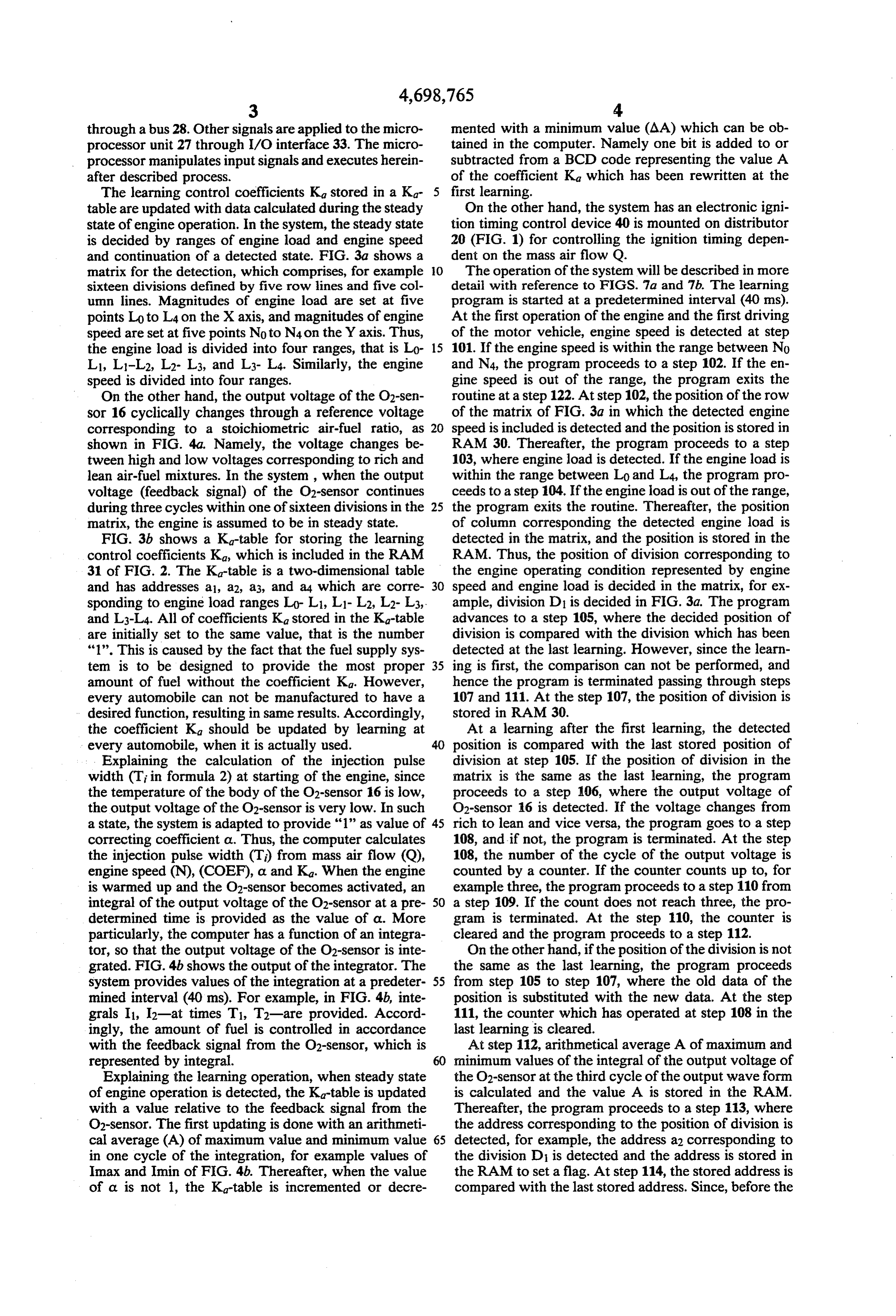
through a bus 28. Other signals are applied to the micro mented with a minimum value (AA) which can be ob processor unit 27 through I/O interface 33. The micro tained in the computer. Namely one bit is added to or processor manipulates input signals and executes herein subtracted from a BCD code representing the value A after described process. of the coefficient Ka which has been rewritten at the The learning control coefficients Kastored in a Ka first learning.
table are updated with data calculated during the steady On the other hand, the system has an electronic igni state of engine operation. In the system, the steady state tion timing control device 40 is mounted on distributor is decided by ranges of engine load and engine speed 20 (FIG. 1) for controlling the ignition timing depen and continuation of a detected state. FIG. 3a shows a dent on the mass air flow Q.
matrix for the detection, which comprises, for example O The operation of the system will be described in more sixteen divisions defined by five row lines and five col detail with reference to FIGS. 7a and 7b. The learning umn lines. Magnitudes of engine load are set at five program is started at a predetermined interval (40 ms). points Loto L4 on the X axis, and magnitudes of engine At the first operation of the engine and the first driving speed are set at five points Noto N4 on the Y axis. Thus, of the motor vehicle, engine speed is detected at step the engine load is divided into four ranges, that is Lor 15 101. If the engine speed is within the range between No L1, L1-L2, L2-L3, and L3-L4. Similarly, the engine and N4, the program proceeds to a step 102. If the en speed is divided into four ranges. gine speed is out of the range, the program exits the On the other hand, the output voltage of the O2-sen routine at a step 122. At step 102, the position of the row sor 16 cyclically changes through a reference voltage of the matrix of FIG. 3a in which the detected engine corresponding to a stoichiometric air-fuel ratio, as 20 speed is included is detected and the position is stored in shown in FIG. 4a. Namely, the voltage changes be RAM. 30. Thereafter, the program proceeds to a step tween high and low voltages corresponding to rich and 103, where engine load is detected. If the engine load is lean air-fuel mixtures. In the system, when the output within the range between Lo and L4, the program pro voltage (feedback signal) of the O2-sensor continues ceeds to a step 104. If the engine load is out of the range, during three cycles within one of sixteen divisions in the 25 the program exits the routine. Thereafter, the position matrix, the engine is assumed to be in steady state. of column corresponding the detected engine load is FIG. 3b shows a K-table for storing the learning detected in the matrix, and the position is stored in the control coefficients K, which is included in the RAM RAM. Thus, the position of division corresponding to 31 of FIG. 2. The K-table is a two-dimensional table the engine operating condition represented by engine and has addresses a1, a2, a3, and a4 which are corre 30 speed and engine load is decided in the matrix, for ex sponding to engine load ranges Lo-L1, L1-L2, L2-L3, ample, division D1 is decided in FIG.3a. The program and L3-L4. All of coefficients Kastored in the Ka-table advances to a step 105, where the decided position of are initially set to the same value, that is the number division is compared with the division which has been "1'. This is caused by the fact that the fuel supply sys detected at the last learning. However, since the learn tem is to be designed to provide the most proper 35 ing is first, the comparison can not be performed, and amount of fuel without the coefficient K. However, hence the program is terminated passing through steps every automobile can not be manufactured to have a 107 and 111. At the step 107, the position of division is desired function, resulting in same results. Accordingly, stored in RAM. 30.
the coefficient Ka should be updated by learning at At a learning after the first learning, the detected every automobile, when it is actually used. 40 position is compared with the last stored position of Explaining the calculation of the injection pulse division at step 105. If the position of division in the width (Ti in formula 2) at starting of the engine, since matrix is the same as the last learning, the program the temperature of the body of the O2-sensor 16 is low, proceeds to a step 106, where the output voltage of the output voltage of the O2-sensor is very low. In such O2-sensor 16 is detected. If the voltage changes from a state, the system is adapted to provide '1' as value of 45 rich to lean and vice versa, the program goes to a step correcting coefficient a. Thus, the computer calculates 108, and if not, the program is terminated. At the step the injection pulse width (T) from mass air flow (Q), 108, the number of the cycle of the output voltage is engine speed (N), (COEF), a and Ka. When the engine counted by a counter. If the counter counts up to, for is warmed up and the O2-sensor becomes activated, an example three, the program proceeds to a step 110 from integral of the output voltage of the O2-sensor at a pre 50 a step 109. If the count does not reach three, the pro determined time is provided as the value of a. More gram is terminated. At the step 110, the counter is particularly, the computer has a function of an integra cleared and the program proceeds to a step 112. tor, so that the output voltage of the O2-sensor is inte On the other hand, if the position of the division is not grated. FIG. 4b shows the output of the integrator. The the same as the last learning, the program proceeds system provides values of the integration at a predeter 55 from step 105 to step 107, where the old data of the mined interval (40 ms). For example, in FIG. 4b, inte position is substituted with the new data. At the step grals I, I2-at times T1, T2-are provided. Accord 111, the counter which has operated at step 108 in the ingly, the amount of fuel is controlled in accordance last learning is cleared.
with the feedback signal from the O2-sensor, which is At step 112, arithmetical average A of maximum and represented by integral. minimum values of the integral of the output voltage of Explaining the learning operation, when steady state the O2-sensor at the third cycle of the output wave form of engine operation is detected, the Ka-table is updated is calculated and the value A is stored in the RAM. with a value relative to the feedback signal from the Thereafter, the program proceeds to a step 113, where O2-sensor. The first updating is done with an arithmeti the address corresponding to the position of division is cal average (A) of maximum value and minimum value 65 detected, for example, the address a2 corresponding to in one cycle of the integration, for example values of the division D is detected and the address is stored in Imax and Imin of FIG. 4b. Thereafter, when the value the RAM to set a flag. At step 114, the stored address is of a is not 1, the K-table is incremented or decre compared with the last stored address. Since, before the
Page 10
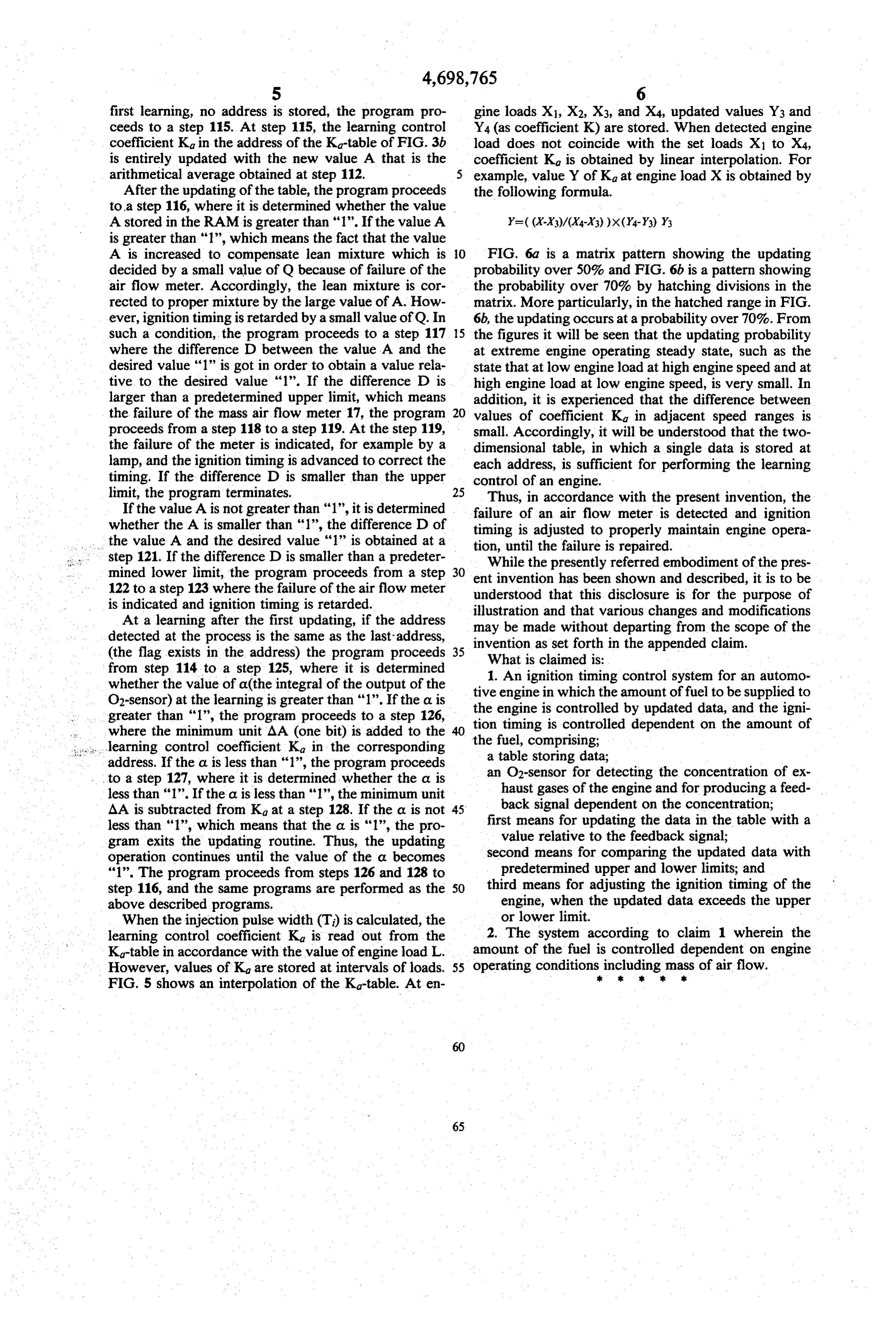
first learning, no address is stored, the program pro gine loads X1, X2, X3, and X4, updated values Y3 and ceeds to a step 15. At step 115, the learning control Y4 (as coefficient K) are stored. When detected engine coefficient Kg in the address of the K-table of FIG. 3b load does not coincide with the set loads X to X4, is entirely updated with the new value A that is the coefficient Kg is obtained by linear interpolation. For arithmetical average obtained at step 112. 5 example, value Y of Ka at engine load X is obtained by After the updating of the table, the program proceeds the following formula.
to a step 116, where it is determined whether the value
A stored in the RAM is greater than "1". If the value A is greater than "1", which means the fact that the value
A is increased to compensate lean mixture which is O FIG. 6a is a matrix pattern showing the updating decided by a small value of Q because of failure of the probability over 50% and FIG. 6b is a pattern showing air flow meter. Accordingly, the lean mixture is cor the probability over 70% by hatching divisions in the rected to proper mixture by the large value of A. How matrix. More particularly, in the hatched range in FIG. ever, ignition timing is retarded by a small value of Q. In 6b, the updating occurs at a probability over 70%. From such a condition, the program proceeds to a step 117 5 the figures it will be seen that the updating probability where the difference D between the value A and the at extreme engine operating steady state, such as the desired value "1" is got in order to obtain a value rela state that at low engine load at high engine speed and at tive to the desired value '1'. If the difference D is high engine load at low engine speed, is very small. In larger than a predetermined upper limit, which means addition, it is experienced that the difference between the failure of the mass air flow meter 17, the program values of coefficient Kg in adjacent speed ranges is proceeds from a step 118 to a step 119. At the step 119, small. Accordingly, it will be understood that the two the failure of the meter is indicated, for example by a dimensional table, in which a single data is stored at lamp, and the ignition timing is advanced to correct the each address, is sufficient for performing the learning timing. If the difference D is smaller than the upper control of an engine.
limit, the program terminates. 25
Thus, in accordance with the present invention, the
If the value A is not greater than "1", it is determined failure of an air flow meter is detected and ignition whether the A is smaller than '1', the difference D of timing is adjusted to properly maintain engine opera the value A and the desired value "1" is obtained at a tion, until the failure is repaired. step 121. If the difference D is smaller than a predeter mined lower limit, the program proceeds from a step 30 entWhile the presently referred embodiment of the pres invention has been shown and described, it is to be 122 to a step 123 where the failure of the air flow meter understood that this disclosure is for the purpose of is indicated and ignition timing is retarded.
At a learning after the first updating, if the address illustration and that various changes and modifications detected at the process is the same as the last-address, invention as setwithout may be made forth departing from the scope of the in the appended claim.
(the flag exists in the address) the program proceeds 35
What is claimed is:
from step 114 to a step 125, where it is determined whether the value of a(the integral of the output of the tive1. engine
An ignition timing control system for an automo
O2-sensor) at the learning is greater than "1". If the a is the engine isin controlled which the amount of fuel to be supplied to by updated data, and the igni greater than '1', the program proceeds to a step 26, where the minimum unit AA (one bit) is added to the tion timing is controlled dependent on the amount of ... learning control coefficient Ka in the corresponding thea fuel, table comprising;
storing data;
address. If the or is less than '1', the program proceeds an O2-sensor for detecting the concentration of ex to a step 127, where it is determined whether the a is haust gases of the engine and for producing a feed less than '1'. If the a. is less than 'l', the minimum unit
AA is subtracted from Ka at a step 128. If the d is not 45 firstback signal dependent on the concentration; means for updating the data in the table with a less than "1', which means that the a. is "1", the pro value relative to the feedback signal; gram exits the updating routine. Thus, the updating operation continues until the value of the a becomes second means for comparing the updated data with "1". The program proceeds from steps 126 and 128 to predetermined upper and lower limits; and step 116, and the same programs are performed as the 50 third means for adjusting the ignition timing of the above described programs. engine, when the updated data exceeds the upper When the injection pulse width (T) is calculated, the or lower limit.
learning control coefficient Ka is read out from the 2. The system according to claim 1 wherein the Ka-table in accordance with the value of engine load L. amount of the fuel is controlled dependent on engine However, values of K are stored at intervals of loads. 55 operating conditions including mass s of air flow.
FIG. 5 shows an interpolation of the Ka-table. At en
Provenance
- Collection
- Cited prior art
- Original PDF
- patentimages.storage.googleapis.com →
- Filed
- 1985-07-22
- Pages
- 10
- Method
- pdftotext (the PDF's own text layer) + pdftoppm 300dpi page scans
- Source
- Google Patents bibliographic record
- Granted
- 1987-10-06
- Inventors
- Kunihiro Abe; Yoshitake Matsumura; Takurou Morozumi; Fuji Jukogyo KK
- Transcribed from
- patentimages.storage.googleapis.com →