patent · US4435043
Composite mirror panels
6 March 1984
Page 1 — bibliographic record
United States Patent (19) 11 4,435,043 Mertens et al. 45) Mar. 6, 1984 (54) COMPOSITE MIRROR PANELS 56) References Cited
75) Inventors: Guy Mertens, Namur; Pierre 4,124,277 11/1978 Stang................................... 350/293 Laroche, Ham-sur-Heure, both of
Belgium Primary Examiner-Paul J. Thibodeau
Attorney, Agent, or Firm-Spencer & Frank 73) Assignee: Glaverbel, Brussels, Belgium 57 ABSTRACT A composite mirror panel comprises a front flexible 21 Appl. No.: 374,908 vitreous sheet 1 whose rear face is provided with a reflective coating 2 to form a mirror 3. A flexible water 22 Filed: May 4, 1982 proof backing sheet 5 is watertightly bonded at 4 to the rear of the mirror 3 to form a laminate 6. A corrugated 30 Foreign Application Priority Data backing sheet 8 is bonded to the first backing sheet 5 along crests 9 of the corrugations to form a composite
Aug. 21, 1981 GB United Kingdom ................. 82S665 mirror panel which is flexible about axes parallel with the corrugations.
51) Int. Cl. ........................... G02B 5/10; B32B 3/28 The first backing sheet 5 may be of vitreouus material 52 U.S. C. .................................... 350/288; 126/438: thicker than the mirror sheet 1 or it may be a metal
126/438; 350/295, 299, 310, 320, 288 18 Claims, 4 Drawing Figures
Page 2
Drawing sheet — no readable text.
Page 3
Drawing sheet — no readable text.
Page 4
ture. It is therefore necessary when making concave
COMPOSTE MIRROR PANELS mirrors of the aforesaid known construction to use a different mould or die for each different mirror curva
BACKGROUND OF THE INVENTION ture, even if such curvatures differ only slightly. When This invention relates to composite mirror panels. making mirrors for solar reflection purposes, eg for use Composite mirror panels are useful for many pur as solar concentrators, mirrors of an appreciable num poses and an increasing use is being found in the field of ber of different curvatures may be required. solar energy collectors. SUMMARY OF THE INVENTION In one form of solar energy transducing installation, O It is an object of the present invention to provide a mirrors are held on supports distributed around a field.
Each support may carry mirrors several square meters mirror panel of a construction such that its surface pro in area and there may for example be a hundred or more file can be varied, but which can nevertheless easily be supports distributed around a field up to a few hectares secured to a rigid supporting structure so that the panel in area. All the mirrors are arranged to reflect solar 5 is held to a predetermined curvature and has a good energy onto for example an energy collecting surface of resistance to flexure under externally applied forces. At a steam generator arranged to drive a turbo-generator. the same time, it is an object of the invention to provide So that the mirrors can continue to reflect sunlight onto such a panel which has good weathering resistance and the energy collecting surface as the sun moves across is therefore suitable for outdoor use, egas a solar energy the sky, the mirror supports incorporate means for ad reflector.
justing the orientation of the mirrors about vertical and 20 According to the present invention, there is provided horizontal axes. The combination of such a mirror and a composite mirror panel comprising a front flexible support is known as a heliostat. Such mirrors may be vitreous sheet whose rear face is provided with a reflec flat or curved. tive coating to form a mirror, a flexible waterproof The efficiency and cost of such a solar energy trans 25 backing sheet (hereafter called "first backing sheet”) ducing installation will depend on a number of factors, water-tightly bonded to the rear of said mirror so as to inter alia, the properties of the heliostat mirrors. form therewith a laminate, and a corrugated backing It is clearly desirable that a solar mirror, whether for sheet which is bonded to said first backing sheet along use in a heliostat or some other form of solar energy crests of such corrugations to form a said composite collector, should have a high reflectivity, and that such 30 panel which is flexible about axes parallel with said reflectivity should be preserved against weathering to corrugations.
give the mirror a long useful life. It is also desirable that Such a composite mirror panel presents a number of the mirror should be substantially rigid when in use. A important advantages as regards its ease of manufacture heliostat mirror may, e.g. be located a hundred meters and in use.
or more away from the collector, in which case even The present invention enables the construction of a quite minor movement or deformation of the mirror due 35 mirror panel whose reflective surface is flexible about to wind gusts would deflect the reflected sunlight away axes parallel with the corrugations. Such a mirror panel from the collector surface. can very easily be mounted rigidly, for example in a The requisite properties of rigidity and weathering support which comprises ribs or joists leading across resistance can best be achieved by combining a mirror the corrugations. Because of the flexibility of the panel, with a protective and strengthening backing means the manufacturer is not committed
which together with the mirror forms a composite mir of accuracy in manufacturing mirrortopanels the same degree ror panel. Composite mirror panels having such proper curvature, since, by virtue of the flexibility,to at a given least ties are useful not only for solar reflectors but also for minor modifications to such curvature can be made in other purposes, for example for use as building panels. situ when securing the composite mirror panel to its It is known, for example from U.S. Pat. No. 45 4,124,277, assigned to Martin Marietta Corporation, to support for use. Indeed, if the degree of flexibility is sufficient, such mirror panels can be made to a single form a composite concave mirror panel by holding a reflective surface normally flat rigid glass mirror in a concave configura modified on site to profile give and this profile can then be composite mirror panels having tion under bending stress within its elastic limit by bonding it to a holding layer of substantially dimension 50 aable range of different curvatures. This is particularly valu in manufacture.
ally stable material, the holding layer being formed by a The strength of the said second backing sheet can layer of open-ended expansible cellular material sand readily wiched between layers of pliable and solidifiable dimen a wholebeisselected so that the composite mirror panel as substantially inflexible about axes normal to sionally stable material. The holding layer is cured in the corrugations, or it may be such as to admit of some situ and bonded to the glass mirror while the mirror is 55 mechanically held in the required concave configura degree of flexure about such axes if that is desired. tion. Aluminium and paper honeycomb structures are It is especially preferred that said laminate is a flat cited as examples of suitable cellular material. It is also laminate when unstressed. It is very much easier to known to form flat mirrors of the same composite struc laminate flat sheets together than it is to laminate ture. 60 curved sheets. The production of flat mirror panels Concave mirrors made in this way must be made so which can be curved in situ also has advantages in ease that each mirror has a predetermined curvature, within of stacking, packaging and transport prior to mounting such manufacturing tolerances as may be allowed for in a support.
their intended use. In the case of solar mirrors, such The laminating of the mirror to the first backing sheet tolerances are very small. In the manufacture of curved 65 prior to the production of the composite mirror panel is mirrors comprising a reflectively-coated glass sheet advantageous because it reduces the risk of breaking the held in flexed condition, the glass sheet is held pressed front vitreous sheet during formation of the panel. Such against a mould face or die of the required mirror curva risk would otherwise be appreciable when a thin vitre
Page 5
ous sheet of large area is used. The production of the which such a laminate forms part can be flexed to a said laminate prior to its use in the formation of the smaller radius of curvature.
panel is also beneficial because it enables separate atten One especially preferred way of making such a flexi tion to be given to the highly important bond between ble laminate is to constitute it as a flexible radiant en the mirror and the first backing sheet. In the finished ergy reflector as described in published British Patent product, the first backing sheet protects or assists in Application Specification No GB 2 042 761. A whose protecting the reflective coating against deterioration disclosure is specifically incorporated into this specifi due to weathering.
The field of primary interest for employment of the cation The by reference.
corrugations of said corrugated backing sheet present invention is that of solar reflectors and particu may have
any desired form, for example they may be larly solar concentrators, that is, concavely curved solar reflectors. rounded or sinusoidal or of rectangular form, but it is Preferably said front vitreous sheet has a thickness of preferred that said corrugated backing sheet has non at most 1.5 mm and preferably within the range 0.6 to reflex trapezoidal corrugations. Such corrugations pro 1.0 mm. In addition to promoting lightness of the panel, 15 vide convenient flat crests or ridges at either side of the this feature has the advantage of enhancing reflectivity sheet for attachment to the first backing sheet and a of the panel since the light path through the vitreous mirror panel support. The webs of the corrugated sheet material will be shorter than when thicker sheets are joining such crests are non-reflexly, that is obtusely, used so that less energy is absorbed by the vitreous angled to the crests to provide the best mechanical sheet, and the perceptibility of double images due to properties for the purposes in view.
reflection from the front and back surfaces of the vitre Advantageously, each crest at either side of such a ous sheet is also reduced. corrugated backing sheet has the same width which is Advantageously each said backing sheet is of a mate different from the common width of the crests at the rial which has a Young's modulus of elasticity of at least other side of the corrugated backing sheet, and said first 10 and preferably at least 50 GN/m2. This promotes 25 rigidity of a composite panel structure formed in accor backing sheet is bonded to the narrower crests. The two backing sheets may be bonded together in dance with the invention. In addition, the use of such a any convenient way. It is to be noted however that such sheet as the first backing sheet is advantageous for im bonding parting good support and protection against breakage to localised techniques stress as spot-welding tend to provide concentrators which can deform the the front vitreous sheet during handling preparatory to reflective surface when the composite mirror panel is bonding of the corrugated backing sheet.
flexed after assembly. Indeed, the
The backing sheets can be made of various materials, welding may itself deform the first backing Enere act of spot for example fibre-reinforced plastics materials, espe thus shet and cially glass-fibre-reinforced plastics materials, and they also deform the reflective surface of an adherent may be of the same or different materials. 35 mirror. In order to avoid or reduce this problem, it is In some preferred embodiments of the invention, said preferred that said first backing sheet is glued to said first backing sheet is a vitreous sheet which is thicker corrugated backing sheet.
than said front vitreous sheet. Vitreous backing sheets Advantageously means for mounting the panel to a can easily be formed to a high degree of planeity for the support are provided by or attached to the corrugated manufacture of flat laminates. backing sheet. For example studs or nuts may be at In other preferred embodiments of the invention, said tached to the rear face of the corrugated backing sheet first backing sheet is a metal sheet. Alternatively or in or holes may be drilled therethrough for the reception addition it is preferred that said corrugated backing of bolts.
sheet is a metal sheet. The or at least one said metal In the most preferred embodiments of panel accord sheet is preferably of steel or aluminium or an alumin 45 ing to this invention, said panel mounting means are ium alloy. Where steel is used, it is preferably galvan only indirectly connected to said first backing sheet. ised to protect it against corrosion. Further protection This reduces the risk of high local stresses, which could against corrosion may be given by applying other pro deform the first backing sheet, being transmitted to it tective coatings to metal sheets when used; for example, directly.
an exposed face of a said backing sheet, where this is of 50 The invention includes a solar energy collector cha steel, may be coated with a silicone polyester. racterised in that it comprises at least one mirror panel To provide a good compromise between strength and as herein defined mounted on a support. Such a mirror weight, the or at least one said metal sheet preferably panel is preferably mounted in a heliostat. In some pre has a thickness in the range 0.5 to 1.5 mm. ferred embodiments of the invention, the or at least one Preferably said front vitreous sheet and said first 55 said mirror panel is held concavely curved by its sup backing sheet are so selected and bonded together that the flexible laminate has a neutral bending surface port.
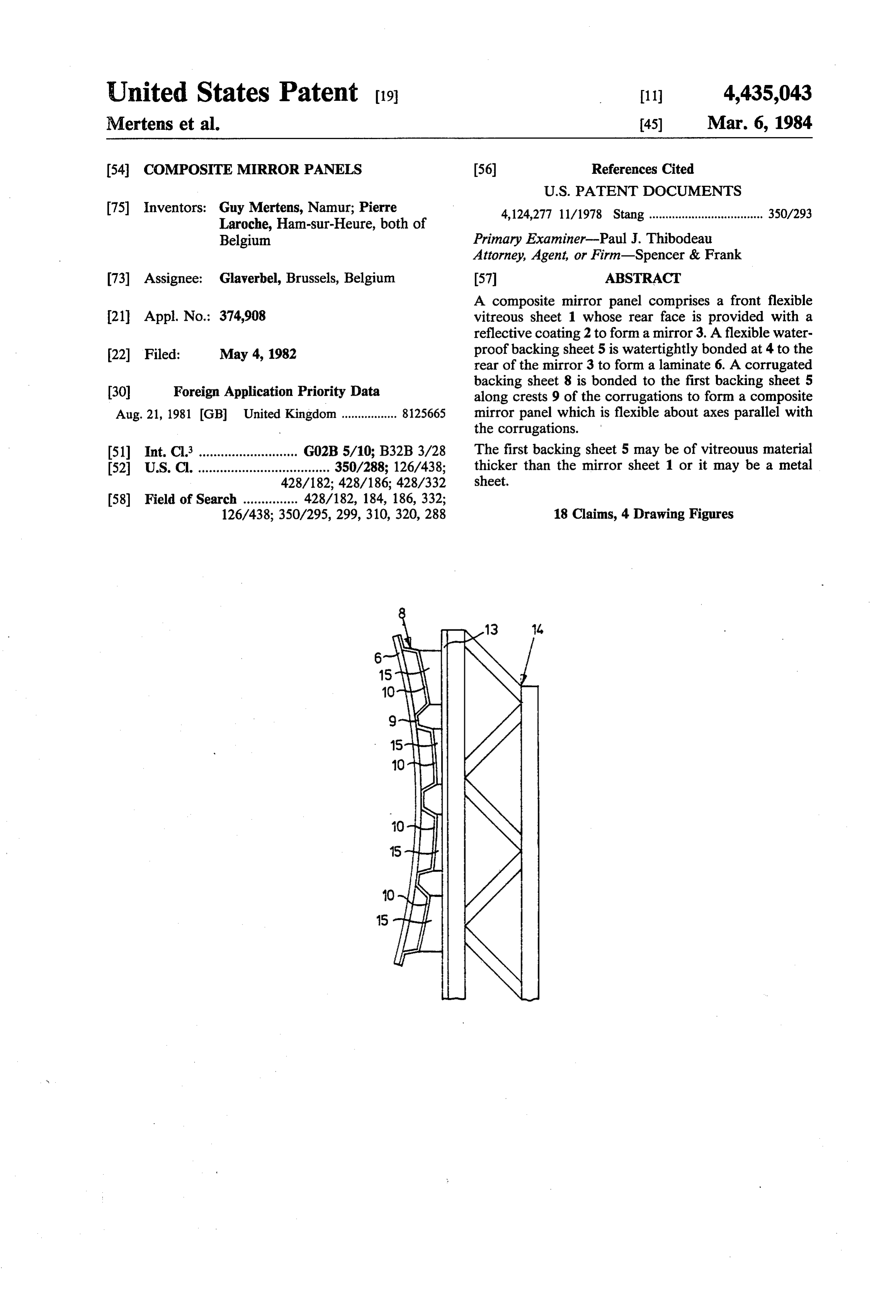
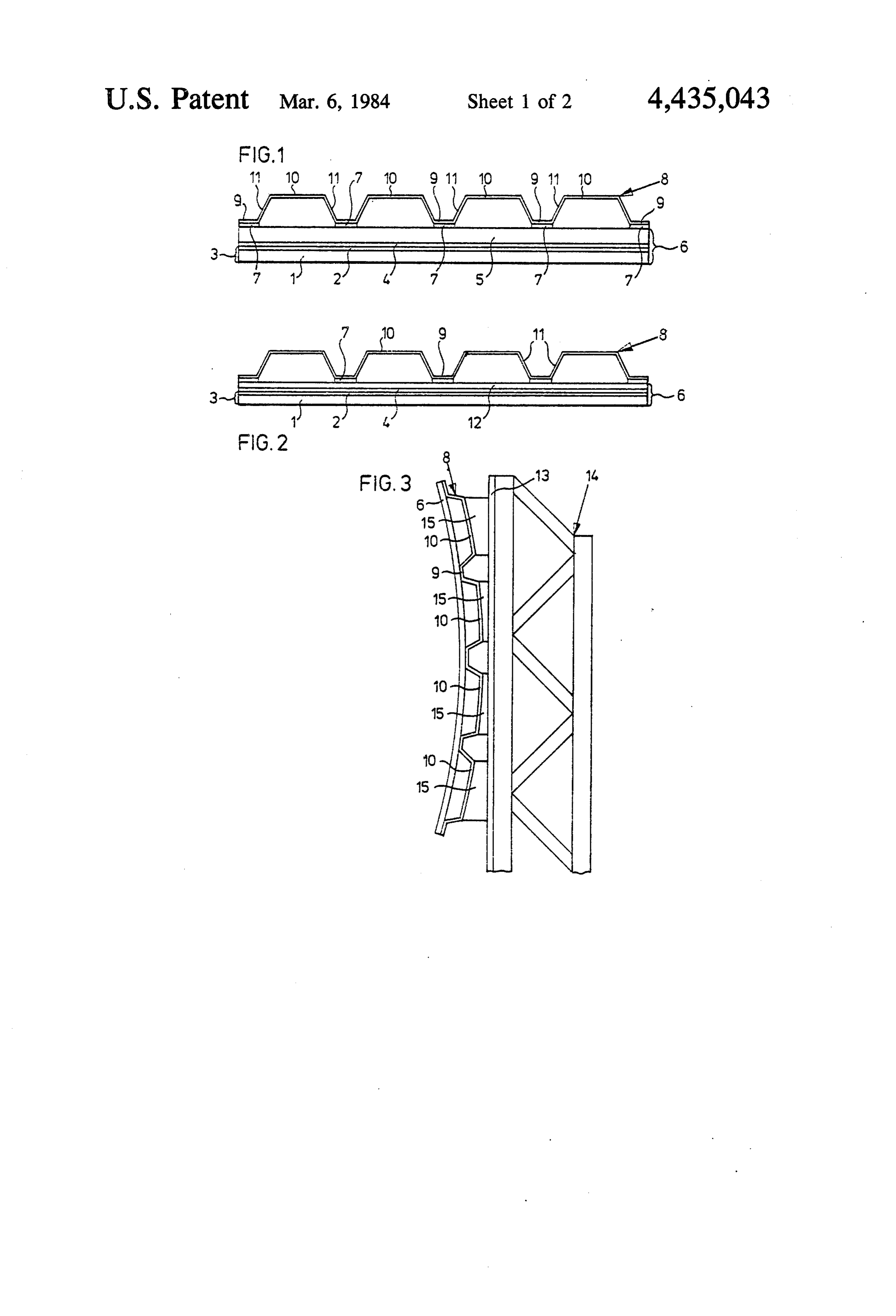
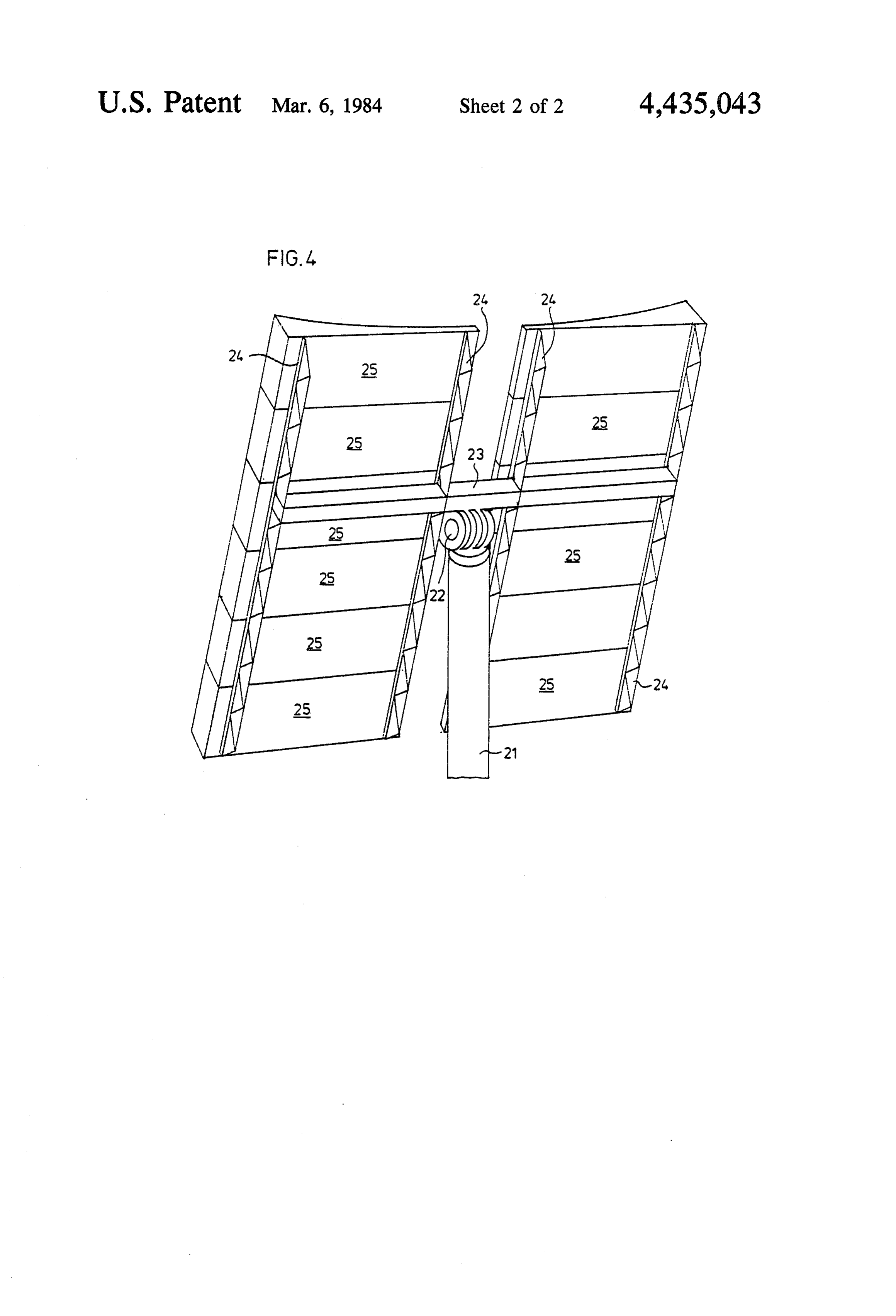
which lies outside the thickness of the front vitreous BRIEF DESCRIPTION OF THE DRAWENGS sheet when the laminate is flexed within the elastic limits of its component sheets to form a concave or 60 Examples of panels according to the invention will more concave reflector. now be described in greater detail with reference to the Because the neutral bending surface of the laminate accompanying diagrammatic drawings in which lies outside the thickness of the front vitreous sheet, that FIGS. 1 and 2 are end elevational views of two mir sheet will be subjected to compression forces and not rors in accordance with the invention; tensile forces when the sheet is so flexed. As is well 65 FIG. 3 shows a detail of a mirror panel mounted known, vitreous materials are generally able to with concavely on a support; and stand compressive forces better than tensile forces with FIG. 4 shows a heliostat support for mounting mirror out breaking, so that the composite mirror panel of panels in accordance with the invention.
Page 6
DETAILED DESCRIPTION OF THE been used to designate like elements and it will be noted
PREFERRED EMBODIMENTS
that the glass backing sheet 5 has been replaced by a thinner backing sheet 12. In this embodiment the back
In FIG. 1, a front glass sheet 1 is provided in known ing sheet 12 is of metal.
manner with a reflective coating 2, for example of sil 5 ver, to form a mirror 3. If desired, the back surface of EXAMPLE 2 the mirror 3 can be painted in known manner, though A laminate 6 as shown in FIG. 2 was made by bond this is not shown. The reflectively coated face of the ing a sheet 1 of ordinary untempered glass, 0.75 mm in front glass sheet1 is bonded by a glue layer 4 to a water thickness, to a metal sheet 12 formed of galvanised steel proof backing sheet 5 (the first backing sheet) to form a 10 and having a thickness of 0.67 mm. Prior to such bond flexible laminate 6. In the embodiment of FIG. 1, the ing the glass ply was provided with a light-reflecting first backing sheet 5 is a glass sheet which is thicker than coating 2 of silver and a protective coating composed of the first glass sheet 1. The first backing sheet 5 is in turn a layer of copper and a layer of protective paint as used glued by bodies of adhesive 7 to a corrugated backing in conventional mirror production.
sheet 8. As indicated, the corrugations of the corru 15 The coated glass and the metal sheet were bonded gated backing sheet 8 are trapezoidal, and the first back together by a layer of an epoxy-based adhesive mar ing sheet 5 is glued to front flat crests 9 of such corruga keted under the Trade Mark ARALDITE by Ciba. It tions which are all of substantially the same width and was found that the laminate could be flexed within the are narrower than the rear crests 10. The webs 11 join elastic limit of the metal to impart to the front face of ing the front and rear crests 9, 10 are non-reflexly an 20 the glass ply a concave curvature as small as 18.5 cm gled to those crests. without breakage of the glass, Continued flexing be EXAMPLE 1. yond the elastic limit led to breakage of the glass when the radius of curvature reached 12.5 cm.
In a specific practical example, to form a mirror panel The laminate 6 was then bonded to a corrugated measuring 1 by 3 m in area, the front glass sheet 1 was 25 backing sheet 8 as described in Example 1 and it was of untempered ordinary soda-lime glass 0.8 mm in thick found that ness and it was silvered in the usual way. The front glass to give the the mirror panel as a whole could be flexed sheet 1 was bonded, using a double-faced adhesive film a radius as low as 3200 mirror a uniform concave curvature with m about an axis parallel to the available under the trade name MACBOND, to the first corrugations.
backing sheet 5 which was also of soda-lime glass but 30 FIG. 3 shows one way in which such a mirror panel was 3 mm thick. Young's modulus of elasticity for soda can be mounted with a curved profile on a support. In lime glass is approximately 72 GN/m2. The first back FIG, 3, a composite mirror panel comprising a mirror/- ing sheet 5 was bonded to the corrugated backing sheet backing 8 using a silicone adhesive furnished by General Elec ing sheetsheet laminate 6 bonded to a corrugated back 8 is attached near one of its ends to a flange 13 tric, The corrugated backing sheet 8 was made from a 1 35 of a supporting joist 14 of truss construction. In the mm thick sheet of aluminium alloy available under the embodiment illustrated, the flange 13 is straight, so in trade name and designation ALCLAD 3003H16-18. order to impart the required curvature to the mirror Young's modulus of elasticity for this alloy is over 65 panel, appropriately shaped spacer pieces 15 are inter GN/m2. The corrugated sheet used was manufactured posed between the rear crests 10 of the corrugated by the SIDAL company under their reference TS 1045. backing sheet 8 and the flange 13. The other end of the The front crests 9 which were bonded to the first back mirror panel could be likewise attached ing sheet 5 were each 30 mm in width and the rear crests 14. The actual attachment of the corrugated to a second joist 10 were each 90 mm in width. The amplitude of the sheet 8 to the spacer pieces 15 and the flange 13backing can be corrugations was 45 mm and their pitch was 160 mm.
By virtue of the bond between the front vitreous 45 by bolts, rivets, welding, e.g. spot welding, or by any sheet 1 and the first backing sheet 5, the neutral bending other FIG.
convenient means.
4 shows a heliostat comprising a support carry surface of the laminate 6 thus formed, that is, the no tional lamella within the laminate where compressive ingThe mirror panels according to the invention. support comprises a pedestal 21 which is held and tensile stresses due to flexure are balanced, lies upright in a foundation sunk to a suitable depth in the within the thickness of the backing sheet 5 when the 50 ground.
laminate is flexed to make the mirror 3 concave. The The upper end of the pedestal 21 carries a drive composite mirror panel of this Example could readily mechanism 22 which supports a generally horizontal be flexed to give its concave mirror surface a radius of beam 23 on which are fixedly mounted four bar joists 24 curvature about an axis parallel to the corrugations of to form a double H or H-H rack assembly. The drive 250 m and a radius of curvature of 340 m about an axis 55 mechanism 22 is controlled by known solar tracking normal to the corrugations without any serious risk of control means (not shown) carried by the support to damage, and when so bent it was noted that stresses pivot the beam 23 about a generally horizontal axis and imposed on the laminate 6 by holding the corrugated about the axis of the pedestal 21. A plurality of gener backing sheet 8 flexed were distributed within the sili ally rectangular composite mirror panels 25 in accor dance with the invention are fixed in two columns be cone adhesive material 7 so that the mirror was not distorted at the bonding zones. tween the bar joists 24 of the H-H rack assembly. The In a variant of the mirror panel described in Example mirror panels 25 are all substantially identical and each 1, the two glass sheets 1, 5 were of the same thicknesses is mounted with its long sides and corrugations gener but were made of tempered soda-lime glass. Such a ally horizontal and its short sides parallel with the bar mirror panel could be bent to shorter radii of curvature. 65 joists 24.
FIG. 2 illustrates an embodiment of composite mirror In a specific practical example, there are two columns panel which is adapted for flexing to lower radii of each of six such mirror panels, each panel measuring 1 curvature. In FIG. 2, the same reference numerals have meter by 3 meters.
Page 7
The panels may be mounted to form a planar reflec 8. A panel according to claim 6 or 7, wherein said tor, or, as is preferred, they may be mounted to form a metal sheet is made of steel or aluminium or an alumin concave reflector. ium alloy.
In another arrangement, the bar joists 24 are them 9. A panel according to claim 6 or 7, wherein said selves curved and the mirror panels are attached be metal sheet has a thickness in the range 0.5 to 1.5 mm. tween them to form a continuously concave reflector 10. A panel according to claim 1, wherein said front having a generally cylindrical or parabolic-cylindrical vitreous sheet and said first backing sheet are selected surface with a generally horizontal axis of curvature. In and bonded together such that said flexible laminate has yet other arrangements, the beam 23 is bent so that a neutral bending surface which lies outside the thick reflected beams of sunlight from the two columns of 0 ness of said front vitreous sheet when said laminate is flexed within the elastic limits of its component sheets to mirror panels will intersect at a desired distance from form a concave reflector. the heliostat. And in a still further arrangement, the mirror panels in each column are concavely flexed 11. A panel according to claim 1, wherein said corru gated backing sheet has non-reflex trapezoidal corruga about an axis parallel to the bar joists supporting that 15 tions.
column.
We claim: 12. A panel according to claim 11, wherein all crests 1. A composite mirror panel comprising a front flexi on each side of said corrugated backing sheet have a common width with the common width of the crests on ble vitreous sheet whose rear face is provided with a one side being reflective coating to form a mirror, a flexible water 20 crests on the different from the common width of the proof first backing sheet water-tightly bonded to the sheet, and wherein said firstofbacking other side said corrugated backing sheet is bonded to rear of said mirror so as to form a flexible laminate, and the narrower crests.
a corrugated backing sheet which is bonded to said first 13. A panel according to claim 1, wherein said first backing sheet along crests of the corrugations to form a backing sheet is bonded to said corrugated backing said composite panel which is flexible about axes paral 25 sheet by glue.
lel to said corrugations.
2. A panel according to claim 1, wherein said lami at 14. A solar energy collector comprising a support and least one composite mirror panel according to claim nate is a flat laminate when unstressed. 1 mounted on said support.
3. A panel according to claim 1 or 2, wherein said 15. A solar energy collector according to claim 14, front vitreous sheet has a thickness of no more than 1.5 30 wherein said at least one composite mirror panel is mounted in a heliostat.
4. A panel according to claim 1, wherein each of said 16. A solar energy collector according to claim 14 or backing sheets is made of a material which has a 15, wherein said at least one composite mirror panel is Young's modulus of elasticity of at least 10 GN/m2. held concavely curved by its said support. 5. A panel according to claim 1, wherein said first 35 17. A panel according to claim 3 wherein said front backing sheet is a vitreous sheet which is thicker than vitreous sheet has a thickness within the range of 0.6 to said front vitreous sheet. 1.0 mm.
6. A panel according to claim 1, wherein said first 18. A panel according to claim 4 wherein each of said backing sheet is a metal sheet. backing sheets has a Young's modulus of elasticity of at 7. A panel according to claim 1, wherein said corru least 50 GN/m2.
gated backing sheet is a metal sheet. x x : x
Provenance
- Collection
- Cited prior art
- Original PDF
- patentimages.storage.googleapis.com →
- Filed
- 1982-05-04
- Pages
- 7
- Method
- pdftotext (the PDF's own text layer) + pdftoppm 300dpi page scans
- Source
- Google Patents bibliographic record
- Granted
- 1984-03-06
- Inventors
- Guy Mertens; Pierre Laroche; Glaverbel Belgium SA
- Transcribed from
- patentimages.storage.googleapis.com →