patent · US6035850
Concentrator for focusing solar radiation
14 March 2000
Page 1 — bibliographic record
United States Patent (19) 11 Patent Number: 6,035,850 Deidewig et al. (45) Date of Patent: Mar. 14, 2000 54 CONCENTRATOR FOR FOCUSING SOLAR 56) References Cited RADIATION U.S. PATENT DOCUMENTS 75 Inventors: Frank Deidewig, Köln; Manfred 4,135,493 1/1979 Kennedy ................................. 126/696 Boehmer, Lohmar; Peter Rietbrock,
Köln, all of Germany
Primary Examiner-Larry Jones 73 Assignee: Deutsches Zentrum fuer Luft- und Attorney, Agent, or Firm-Diller, Ramik & Wight, PC Raumfahrt e.V., Bonn, Germany 57 ABSTRACT
21 Appl. No.: 09/222,824 A concentrator for focusing Solar radiation onto an elongate absorber, comprising a plurality of transverse Supports 22 Filed: Dec. 30, 1998 arranged one behind the other in the longitudinal direction, Stabilizing the concentrator in the transverse direction and 30 Foreign Application Priority Data defining the shape of the concentrator profile, and a thin walled Support Structure resting on Said transverse Supports
Jan. 14, 1998 DE Germany ........................... 198 O1 O78 and having a plurality of adjacent longitudinally extending (51) Int. Cl." ......................................................... F24J 2/10 ribs Stabilizing the concentrator in the longitudinal direction. 52 U.S. Cl. .......................... 126/696; 126/692; 126/684; In the transverse direction, the Support Structure adapts to the 126/680; 126/681; 126/683 curved profile of the transverse Supports and forms a light weight and Strong bearing for a reflector plate.
58 Field of Search ..................................... 126/696, 692, 126/684, 680, 681, 683 13 Claims, 2 Drawing Sheets
Page 2
Drawing sheet — no readable text.
Page 3
Drawing sheet — no readable text.
Page 4
CONCENTRATOR FOR FOCUSING SOLAR absorber. Also with the facet structure, the design of the RADATION Support Structure for the reflector poses. Some problems, because the Support Structure has to shape the reflector while
BACKGROUND ART being rigid at the same time to prevent torsion in the The present invention relates to a concentrator for focus reflector. Prior Support Structures are of complicated design ing Solar radiation onto an elongate absorber Such as in a and are heavy, increasing the costs of a Solar power plant. Solar-thermal power plant, for example. SUMMARY OF THE INVENTION Solar collectors often use trough Systems. Such Systems comprise an elongate through-shaped concentrator that uSu It is an object of the present invention to provide a ally has a parabolic croSS Section. The absorber, through light-weight and Strong concentrator for focusing Solar which a heat transfer medium circulates, is of tubular shape radiation.
and is arranged in the focal line of the concentrator. The The concentrator of the present invention has an elongate reflectors of these concentrators are most often made of shape with a continuous longitudinal Support on which a Self-Supporting composite glass Silvered on the rear Surface. 15 plurality of transverse Supports are arranged Sequentially in At a thickness of 6 to 8 mm, these glass mirrors are rather the longitudinal direction, the transverse Supports providing heavy which becomes evident in particular with great aper the concentrator with Stability in the longitudinal direction. ture widths that extend to up to 6 m. Due to the self Further, a thin-walled Support Structure is provided resting Supporting properties of the composite glass, the Support on the transverse Supports and comprising a plurality of Structures for these reflectors merely have to Support the abutting longitudinally extending ribs having a Stabilizing weight of the reflectors. A shaping Support of the reflectors effect in the longitudinal direction. A reflector plate focusing is not necessary in this case. the Solar radiation onto an absorber rests on this Support In the past, efforts were made to Simplify the Structure of Structure. By Separating the longitudinal and transverse parabolic trough-shaped concentrators So as to lower the Stabilization, the transversely flexible and longitudinally costs of a plant. For example, sheets and other thin-layer 25 rigid Support Structure allows for an optimum adaptation of mirrors, Such as anodized aluminum sheets or polymeric the Support Structure and, thus, of the reflector plate resting films, have been used for reflectors. Compared to composite on the Support Structure, to the required croSS Section of the glass, this entailed a significant reduction in weight. It is a concentrator. Further, the combination of a few transverse disadvantage, however, that these thin-layer mirrors do not Supports on a longitudinal Support and a light-weight lon have the Self-Supporting properties of composite glass. gitudinally extending Support Structure makes it possible to Therefore, Sophisticated Support Structures are required that keep the weight of the Structure of the concentrator very low Support the thin-layer mirrorS Such that they are maintained without any losses in Stability. A complicated Substructure in a parabolic shape. Additionally, the width of the aperture for the concentrator can therefore be omitted. Due to its low has to be increased when using these thin-layer mirrors, weight and its great Stability, the present concentrator resists Since the reflection of Solar radiation is Somewhat leSS for 35 deformation caused by weight forces or wind Stresses and by aluminum sheets and films than for Silver-coated optical the tracking, respectively. The present concentrator allows glasses. The large aperture widths of these concentrators for optional concentrator croSS Sections to be realized. The offer a large area of attack to wind So that Strong Support curvature is determined by the transverse Supports, the Structures are required. However, known Support Structures transversely flexible Support Structure and, thus, the reflector of aluminum or Steel are very complicated and heavy, which 40 plate resting thereon, adapting to this curvature. Therefore, makes them correspondingly expensive. U.S. Pat. No. 4,243, this concentrator may be realized as a parabolic trough shape 019 that forms the precharacterizing part of claim 1, or as a facet shape. The rotational axis for making the describes a trough-Shaped Solar concentrator comprising concentrator track the course of the Sun is disposed within two Side members between which a corrugated Support the longitudinal Support, which is advantageous in that, due element extends in the longitudinal direction, a reflective 45 to the central arrangement of the rotational axis, only low Surface being attached on the Support element. Struts are torques are needed to move the concentrator. fastened to the transverse faces of the Side members, the Preferably, the ribs of the support structure are trapezoidal Struts being connected with a receptacle Surrounding an in croSS Section. Thus, the top and bottom faces of the absorber pipe. The receptacle is mounted for rotation on a Support Structure have bearing faces. At the bottom bearing Stand So that the entire concentrator may be moved to track 50 faces, the Support Structure may be fastened to the transverse the course of the Sun. Since the axis of rotation of the supports by rivets or bolts, for example, while the reflector concentrator, which coincides with the axis of the absorber plate rests on the top bearing Surface or is glued thereto, for pipe, is disposed far above the Supporting Structure of the example. If the reflector plate just rests on the Support, a concentrator, a Sophisticated Stand Structure is necessary and retaining means engages over the lateral edges thereof. This a great torque has to be applied to make the concentrator 55 offers the advantage that the reflector plate may expand track the course of the Sun. unrestrictedly in case of temperature variations, without any It is another problem of large aperture widths that the ensuing Stresses or torsion therein.
distances between the individual troughs have to be rather great So that no shadows are cast in the morning and in the DETAILED DESCRIPTION OF THE DRAWINGS evening (given a north-to-South orientation). For a more 60 effective exploitation of the given Surface areas and for a of The following is a detailed description of an embodiment the present invention with reference to the accompanying reduction of the wind stresses, trough-shaped concentrators drawings.
of facet structure have been proposed. With such a facet In the Figures:
Structure, the concentrator is divided into a plurality of
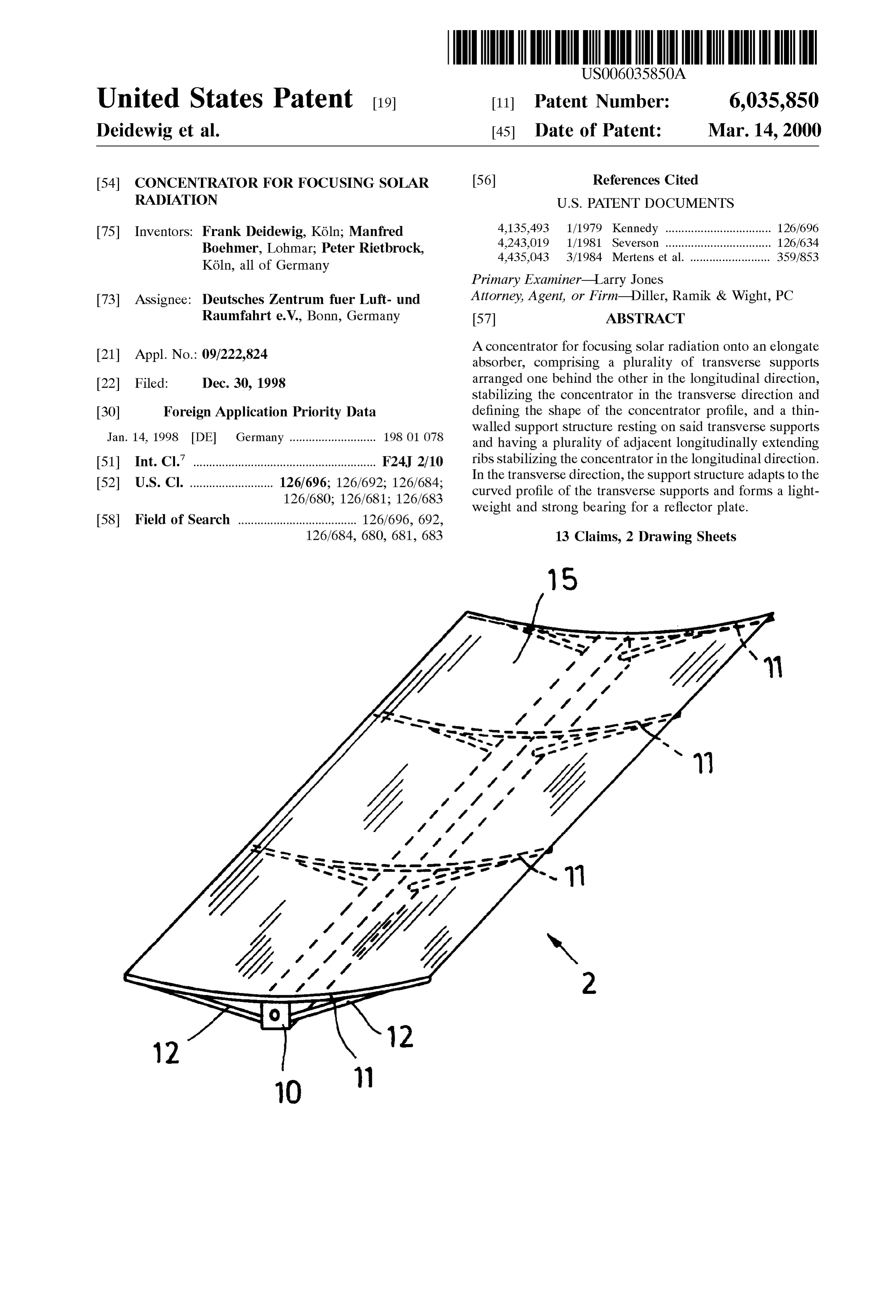
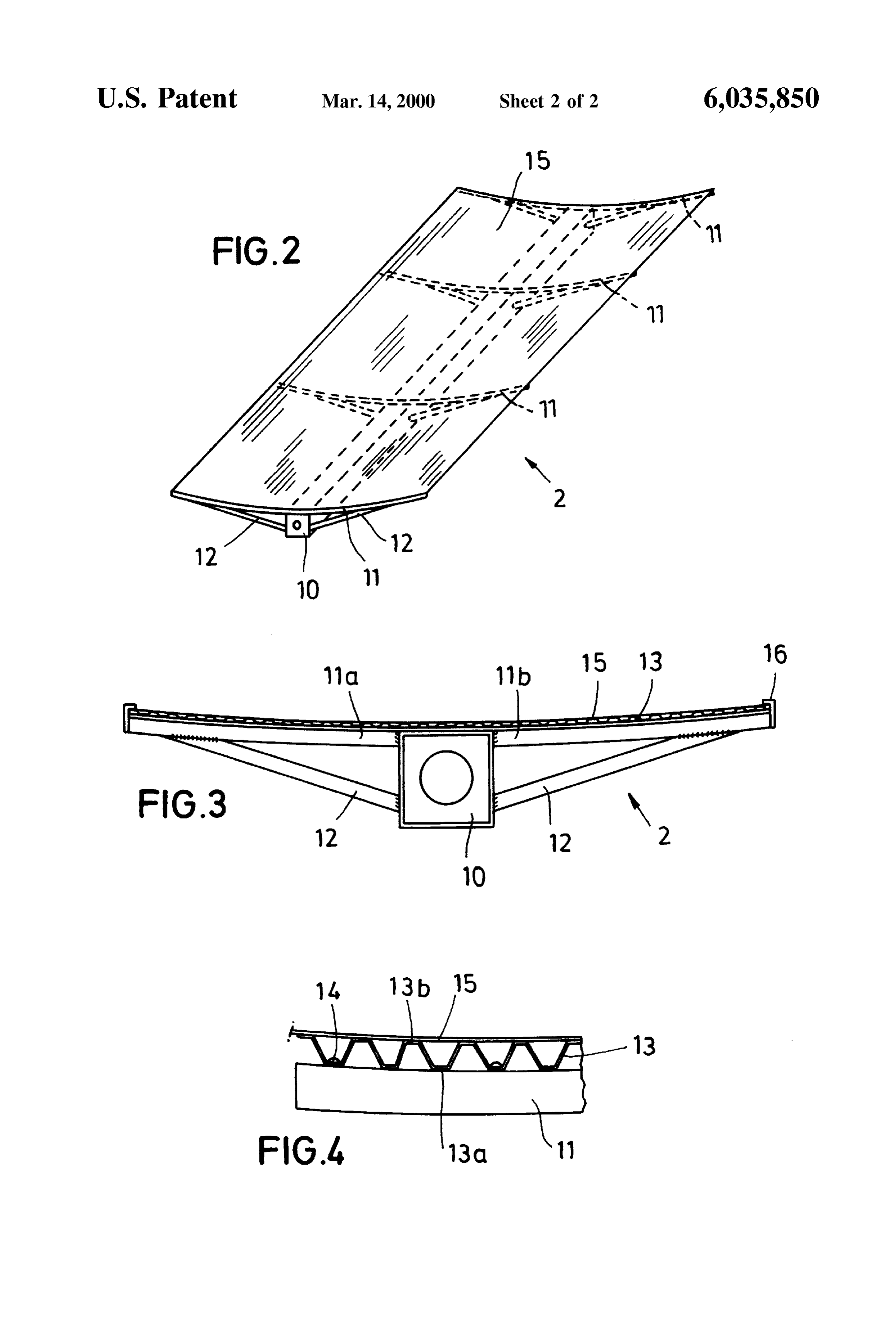
Segments arranged Side-by-Side on one level. These Seg 65 FIG. 1 is a perspective view of a concentrator realized as ments track the Sun individually So that the Solar radiation a facet Structure, reflected by this Segment is always concentrated onto the FIG. 2 is a perspective View of an individual concentrator,
Page 5
FIG. 3 is a front view of the concentrator, and The Supporting elements, namely the longitudinal Support FIG. 4 is a detail of the concentrator. 10, the transverse support 11 and the support structure 13, are arranged below the reflector plate 15 so that these
DETAILED DESCRIPTION OF A PREFERRED members will not cast a shadow on the reflector plate 15. EMBODIMENT Due to the light-weight Structure of the concentrator 2, the Same may be readily produced and transported even in large
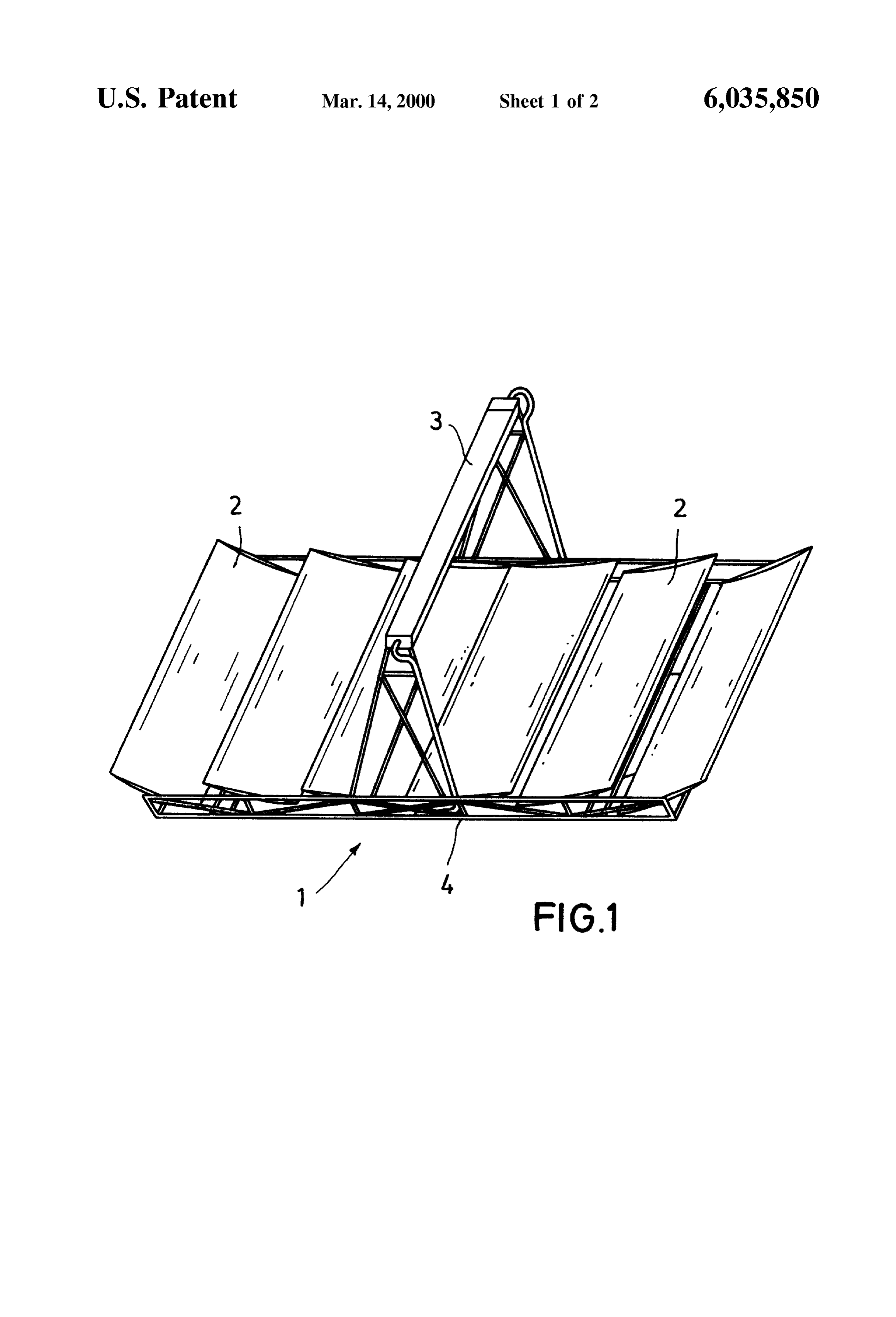
FIG. 1 illustrates a solar power plant 1 of facet trough dimensions.
shape design. A plurality of elongate concentrators 2 focus Although the present invention has been described with the incident Solar radiation onto an absorber 3 through which reference to a particular embodiment thereof, an expert in a heat transfer medium flows. Each concentrator 2 is the field will readily find various possibilities for modifica mounted for rotation on a Substructure 4 So that they may tions and variations. These modifications and variations are track the course of the Sun individually to focus a maximum covered by the present invention as defined by the accom panying claims.
amount of Solar radiation onto the absorber 3.
What is claimed is:
The concentrator 2 illustrated in FIGS. 2 and 3 comprises 1. A concentrator comprising a longitudinal Support, a a longitudinal Support 10 extending in the longitudinal 15 plurality of transverse Supports arranged in Substantially direction over the entire length of the concentrator 2, the Side-by-side longitudinally spaced relationship to each Support being designed at the same time to Serve as a other, Said longitudinal Support being disposed Substantially rotational axis for tracking the concentrator 2. The top of the medially of each of Said transverse Supports, a thin-walled longitudinal support 10 is provided with a plurality of Support Structure Spanning Said transverse Supports, Said curved transverse Supports 11 disposed one behind the other thin-walled Support Structure having a plurality of trans in the longitudinal direction. The croSS Section of the trans versely adjacent longitudinally extending ribs, a reflector verse Support 11 determines the trough croSS Section of the plate resting upon Said Support Structure, Said longitudinal concentrator 2. Depending on the use of the concentrator, e. Support including means for defining a longitudinally g. as a parabolic trough-shaped concentrator or asa com extending pivot axis about which Said concentrator can paratively flat concentrator in a facet trough, the curvature of pivot, each of Said transverse Supports being defined by a the transverse support 11 varies. As illustrated in FIG. 2, the 25 pair of upper aligned Support members each having a first transverse Support 11 may extend over the entire width or it end Secured to Said longitudinal Support and a remote Second may comprise two transverse Support elements 1a, 11b end, each of Said transverse Supports being further defined provided on the sides of the longitudinal Support 10, as by a pair of reinforcing Struts each having a first end Secured shown in FIG. 3. to one of Said upper Support member Second ends and a The transverse Supports 11 are further Supported at the Second end Secured to Said longitudinal Support, and each longitudinal support 10 by struts 12. This assembly of the Support member and its reinforcing Strut Setting-off an acute longitudinal Support 10, the transverse Supports 11 and the angle therebetween.
Struts 12 is light-weight and very Strong in the transverse 2. The concentrator as defined in claim 1 wherein Said direction. One could also increase the Strength in the lon longitudinal Support includes axially opposite end portions, gitudinal direction by inserting further transverse Supports 35 at least one of Said transverse Supports is arranged at each of 11 into the rather wide Spaces between the existing trans Said longitudinal Support end portions, and at least one verse Supports 11. further transverse Support is arranged between Said longitu A lighter Structure may be obtained with a Support Struc dinal Support end portions.
ture 13 illustrated in FIG. 4. The Support structure 13 is 3. The concentrator as defined in claim 1 wherein said ribs made of a thin-walled, light-weight and Strong material, 40 are Substantially trapezoidal in transverse croSS Section. Such as sheet metal, and comprises a plurality of adjacent 4. The concentrator as defined in claim 1 wherein said ribs longitudinally extending ribs, each having a trapezoidal are Substantially corrugated in transverse croSS Section. croSS Section. Therefore, the Support Structure 13 is very 5. The concentrator as defined in claim 1 wherein the Strong in the longitudinal direction, yet flexible in the transverse Supports are of a Substantially curved configura transverse direction, whereby it adapts to the curvature of 45 tion.
the transverse Supports 11. 6. The concentrator as defined in claim 1 wherein the Bearing portions 13a of the support structure 13 rest on transverse Supports are of a Substantially curved parabolic the transverse Support 11. These bearing portions 13a are configuration.
7. The concentrator as defined in claim 1 wherein the wide enough to receive the head of a Screw or a rivet 14 transverse Supports are of a Substantially curved circular connecting the Support Structure 13 with the transverse configuration.
Support 11. A reflector plate 15 rests on the top bearing 50 8. The concentrator as defined in claim 1 wherein the portions 13b. The reflector plate 15 is made of anodized aluminum sheet or a film mirror, for example. The contour reflector 9. The plate is constructed from thin Sheet metal.
concentrator as defined in claim 1 wherein the of the reflector plate 15 is determined through the curved transverse Support 11 and the transversely flexible Support reflector plate is constructed from thin film. structure 13 fastened thereon. The Support structure 13 55 ribs10.areThe concentrator as defined in claim 2 wherein said Substantially trapezoidal in transverse croSS Section.
adapts exactly to the curvature of the transverse Support 11 11. The concentrator as defined in claim 2 wherein said so that the plurality of the top bearing surfaces 13b forms an exact shape for the flexible reflector plate 15. ribs are Substantially corrugated in transverse croSS Section. 12. The concentrator as defined in claim 2 wherein the
The reflector plate 15 may either be glued onto the top transverse Supports are of a Substantially curved configura bearing surfaces 13.b of the Support structure 13 or it may tion.
merely be laid thereon. When the reflector plate 15 is merely 13. The concentrator as defined in claim 2 wherein the laid onto the Support Structure, the lateral edges of the transverse Supports are of a Substantially curved parabolic Support Structure 13 are provided with retaining means 16 configuration.
that engage over the reflector plate 15 to ensure contact between the reflector plate 15 and the support structure 13.
Provenance
- Collection
- Cited prior art
- Original PDF
- patentimages.storage.googleapis.com →
- Filed
- 1998-12-30
- Pages
- 5
- Method
- pdftotext (the PDF's own text layer) + pdftoppm 300dpi page scans
- Source
- Google Patents bibliographic record
- Granted
- 2000-03-14
- Inventors
- Frank Deidewig; Manfred Boehmer; Peter Rietbrock; Deutsches Zentrum fuer Luft und Raumfahrt eV
- Transcribed from
- patentimages.storage.googleapis.com →