patent · US4211620
Method of and apparatus for producing hydrogen and oxygen by photoelectrically-induced electrolysis
8 July 1980
Page 1 — bibliographic record
United States Patent (19) (11) 4,211,620 Fowler 45) Jul. 8, 1980 (54) METHOD OF AND APPARATUS FOR FOREIGN PATENT DOCUMENTS
PRODUCING HYDROGEN AND OXYGEN
BY PHOTOELECTRICALLY-INDUCED 2301709 2/1975 France ..................................... 204/129
ELECTROLYSS
Primary Examiner-R. L. Andrews (75) Inventor: Herbert Fowler, Lexington, Ky. Attorney, Agent, or Firm-Quaintance, Murphy & Richardson 73) Assignee: Childers-Fowler Research and
Development Company, Lexington, 57 ABSTRACT
Ky. Hydrogen and Oxygen are produced by photoelectri (21) Appl. No.: 44,650 cally-induced electrolysis wherein solar and/or laser light is passed through a thin layer of a water-caustic 22) Filed: Jun. 1, 1979 soda solution to ionize the solution adjacent an anode. A cathode spaced from the anode and connected thereto (51) Int. Cl’.......................... C25B 1/04; C25B 9/00; by a diode circuit, including a resistance, is used to C25B 9/04 prevent current flow between the anode and cathode (52) U.S. C. ............................. 204/129; 204/157.1 R; until the potential therebetween exceeds a threshold 204/194; 204/278; 204/DIG. 11 two volts and preferably 2.4 volts. Upon sufficientioni (58) Field of Search ........ 204/129, 157.1 R, DIG. 11, zation in the thin layer of solution, the potential be 204/194, 278 tween the anode and cathode exceeds the threshold and (56) References Cited current flows therebetween, causing hydrogen gas to form at the cathode. Circulation of the solution between
3,925,212 12/1975 Tchernev ...................... 204/157.1 R heating of the fluid with solar or laser light. 4,045,315 8/1977 Fletcher..... a was a wo 204/157.1 R 4,105,517 8/1978 Frosch .......................... 204/157.1 R 20 Claims, 2 Drawing Figures
Page 2
Drawing sheet — no readable text.
Page 3
ized by light passing through the transparent face. A
METHOD OF AND APPARATUS FOR cathode, spaced from the anode, separates hydrogen gas PRODUCING HYDROGEN AND OXYGEN BY from the electrolytic solution as the solution circilates PHOTOELECTRICALLY-INDUCED and a diode circuit, including a resistance, prevents ELECTROLYSS current from flowing between the cathode and anode
BACKGROUND OF THE INVENTION
until there is sufficient potential therebetween to effect the electrolysis process.
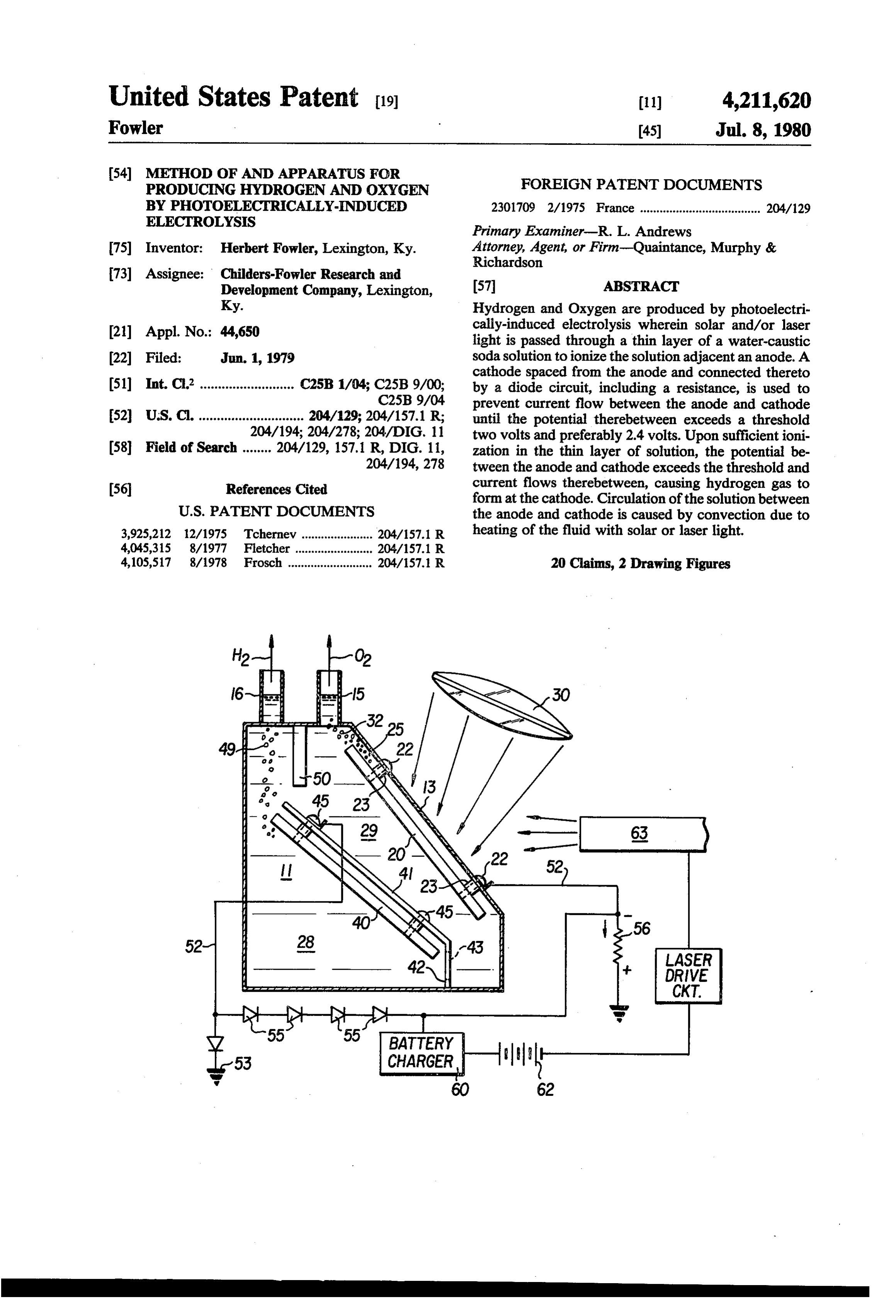
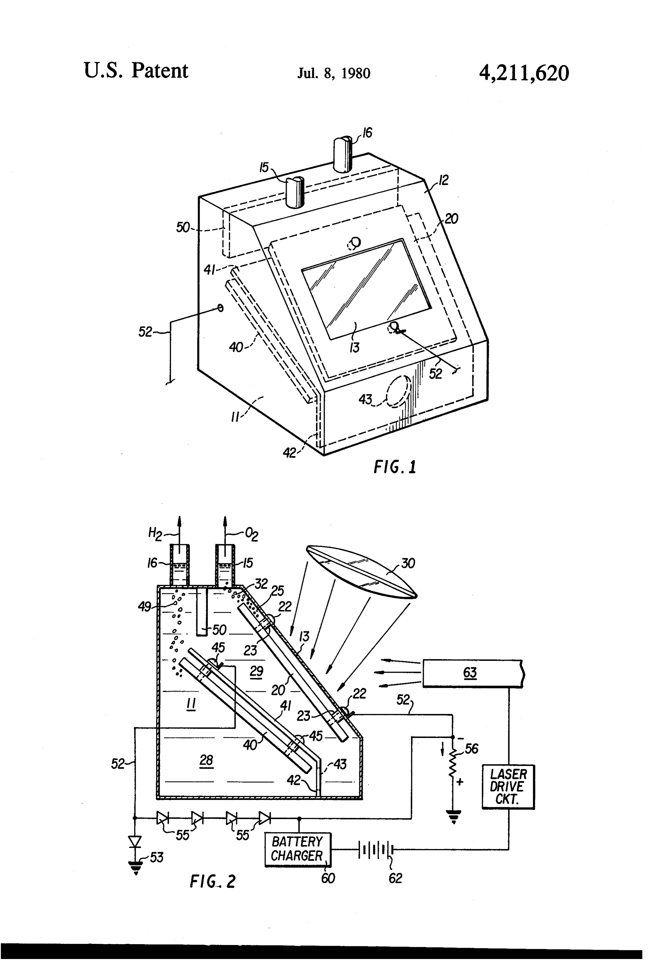
1. Field of the Invention BRIEF DESCRIPTION OF THE DRAWINGS This invention relates to methods of and apparatus for producing hydrogen and oxygen gas from water by O FIG. 1 is a prospective view of apparatus according electrolysis, and more particularly, this invention re to the instant invention showing a container for contain lates to methods of an apparatus for generating hydro ing an electrolytic solution within the container illus gen and oxygen gas from water by electrolysis using trated in phantom, and photoelectric phenomenon. FIG. 2 is a side view of the apparatus showing the 2. Technical Considerations and Prior Art 15 container with one wall removed so as to illustrate the Generation of hydrogen and oxygen gas by electroly various spacial and angular relationships between com sis of water is a widely practiced technique which has ponents and the container. been known for generations. Electrolysis requires elec DESCRIPTION OF THE PREFERRED trical power to create a current between an anode and EMBODIMENT cathode in order to break water into its hydrogen and oxygen components. In recent years, great concern has Referring now to the drawings, there is shown a been expressed as to a pending energy crisis. Hydrogen container, generally designated aby the numeral 10, is a clean, plentiful and readily usable fuel. An efficient, which contains an electrolytic solution 11 that is prefer economical method of producing hydrogen from water ably 75% water and approximately 25% caustic soda or can greatly improve the chances for relieving this crisis. sodium hydroxide (NaOH). The tank is made of or at Consequently, there is now a great deal of effort being lease lined with insulating materials and formed therein expended to develop new and efficient techniques for for admitting light. Preferably, the transparent section producing hydrogen. 13 is made of quartz so as to admit ultraviolet light. The In order to reduce or eliminate the need for an exter nal energy source to produce hydrogen (and hydrocar 30 container 10 has a horizontal top surface 14 with a pair bons), solar energy is being explored as an energy of pipes 15 and 16 to collect oxygen and hydrogen, source. One approach being actively explored is chemi respectively.
An anode 20 is positioned parallel with and in spaced cal processes which resemble photosynthesis in order to relation adjacent to the transparent face plate 13. Pref. convert water and air into combustible hydrocarbons.
Another approach, which is the approach taken by the 35 erably, the anode has an area twice as large as the area instant invention, is to accomplish production of hydro defined by the face plate 13. The anode 20 is preferably made of an alloy known as INCOLOY 800 which is gen gas by using sunlight to effect electrolysis of water. immune
Generally, the emphasis with electrolysis has been to to the corrosive effects of caustic soda. Two use some type of exotic solid state photoelectric cell to bolts 22 are used to retain the anode 20 on the support generate current and release hydrogen and oxygen. To ing surface of transparent face plate 13. Bushings 23 on date, the solid state photoelectric approach has not each of the bolts 22 hold the anode 20 spaced a distance proven economically fruitful. of approximately one-tenth of an inch from transparent face plate 13, so as to define a space 25 therebetween
SUMMARY OF THE INVENTION which will accommodate a relatively thin layer of the In view of the foregoing considerations, it is an object 45 electrolytic solution 11.
of the instant invention to provide a new and improved In accordance with one approach, sunlight is focused method of an apparatus for generating hydrogen and through a quartz magnifying lens 30 so as to pass oxygen by photoelectrically-induced electrolysis. through the transparent face plate 13 and the thin layer In view of the foregoing object, and other objects, of electrolytic fluid in space 25. The light is focused at the instant invention contemplates a method of produc 50 a point 31 behind the anode 20 so as to distribute light ing hydrogen and oxygen from an electrolytic solution over the area presented by the thin layer of fluid in the in an electrolytic cell by, in essence, forming a relatively space 25. The anode 20 is, of course, opaque so that no thin layer of the electrolytic solution adjacent to an light passes therebeyond. As will be explained hereinaf anode and then passing light through the relatively ter, the sunlightionizes the solution so as to split oxygen layer to ionize the electrolytic solution and thereafter 55 from the solution. The oxygen collects on the anode 20 moving the electrolytic solution over a cathode electri in the form of bubbles 32 that bubble out of the solution cally connected to the anode to generate hydrogen gas and up through the oxygen collection pipe 15 for subse on the cathode. In a preferred embodiment, the light quent storage or other use.
passed through the relatively thin layer of electrolytic A cathode 40 is retained within the container 10 on a solution is sunlight. The instant invention further con flange 41 of insulating material which serves as a baffle templates applying the light in the form of a laser beam. to separate the container 10 into anode and cathode According to the instant invention, an apparatus for compartments 28 and 29 respectively. The baffle 40 is practicing the method includes a container for contain disposed at an angle to the horizontal and has a vertical ing the electrolytic solution, the container having a flange 42 at the lower end thereof. The vertical flange transparent face thereon and an anode disposed adja 65 42 has an opening 43 therethrough which permits circu cent to the transparent face to form a relatively thin lation of the electrolytic solution 11 between the anode space between the face and anode. The thin space re and cathode compartments 28 and 29. The cathode 40 is tains a thin layer of electrolytic solution which is ion mounted on the baffle 41 by bolts 45 having bushings 46
Page 4
that hold the cathode in spaced relation to the baffle. If one assumes that before photon ionization takes When the cell is in operation, hydrogen collects on the place at the anode 20 there is no potential difference cathode 40 in the form of bubbles 49 which are col between the anode 20 and cathode 40 then when there lected by the hydrogen outlet pipe 16 which is sepa is a fresh supply of the electrons for the anode this rated from the oxygen collection pipe 15 by a vertical relationship is changed and the cathode becomes posi baffle 50 projecting downwardly from the top surface tive with respect to the anode. This difference in poten 14 of the container 10. tial occurs across the resistor 56. As mentioned before, The anode 20 and cathode 40 are electrically wired to when the potential exceeds 2.4 volts there is a forward one another by a line 52 which is grounded at 53 and 54. bias on the diodes 55 and current flows through the The line 52 includes a plurality of diodes 55 arranged in 10 wire 52 from the anode 20 to the cathode 40. The cur series with one another and a resistor 56 in parallel with rent also flows from the cathode 40 and into the solution the diodes 55. The resistor 56 and diodes 55 prevent 11 thereby creating more NaOH and also hydrogen gas current from flowing from anode 20 to cathode 40 until (H2) which collects on the cathode 40 and flows out of the potential difference therebetween exceeds two 15 the hydrogen outlet 16.
volts. Preferably, the resistance provided by the resistor Devices which rely on sunlight for their operation 56 is sufficient to prevent current flow in the line 52 must contend with periods of cloudiness. In order to until the potential between the anode 20 and cathode 40 keep the apparatus of the instant invention functioning exceeds 2.4 volts at which time the four diodes 55 will during cloudy periods a battery charger 60 is wired to become forward biased allowing current to flow from 20 the line 52 in order to charge a battery 62. The battery the anode 20 to the cathode 40. 62 is used to power a laser 63 which passes a scanning The theory behind operation of the apparatus as de laser beam through the electrolyte in space 25 when scribed above is that electrolytic ionization can occur there is insufficient sunlight through the magnifying when an acid, base, or salt is dissolved in water or any lens 30. There are several approaches for making a laser other disassociating solvent, wherein a part or all of the 25 beam scan. For example, the approach shown in U.S. molecules of the dissolved substance are ionized. Some Pat. No. 3,437,951 may be used. of the ions are positively charged (cations) and an In summary, neutralization by photons of the electro equivalent are negatively charged (anions). According lytic solution 11 in a surface area approximately one to the Helmholtz double layer theory when a metal or half the size of the anode 20 generates electrons which other substance capable of existing in a solution of ions 30 are pulled out of the anode by the solution to thereafter is placed in water, or any other disassociating solvent, a move back into the anode creating a total circuit cur part of the metal or other substance passes into solution rent flow.
in the form of ions. The remainder of the metal or other The foregoing examples are merely illustrative of the substance is therefore left charged with an equivalent invention which is to be limited only by the following amount of electricity of opposite sign from that carried 35 claims.
by the ions. A difference in potential between the metal I claim:
and solvent therefore occurs. Accordingly, if the solu 1. A method of producing hydrogen and oxygen from tion around one of the electrodes (anode 20 or cathode an electrolytic solution in an electrolytic cell compris 40) is neutralized, the electrode will take back some of ing the steps of:
the electrons that the electrolytic solution took away. In 40 forming a relatively thin layer of the electrolytic the disclosed embodiment the solution 11 adjacent the solution on an anode;
anode 20 in the space 25 is neutralized by photons and passing light through the relatively thin layer to ion thus the anode 20 becomes more negative than the cath ize the electrolytic solution in the relatively thin ode 40. Consequently, a difference in potential is set up layer to form oxygen adjacent the anode and to between the anode 20 and cathode 40. Movement of 45 current from the solution 11 into the anode 20 will heat the solution in the layer; decompose the caustic soda and water and oxygen (O2) circulating the fluid in the electrolytic cell due to will form on the anode 20. heating of the relatively thin layer to move the Since the space 25 between the transparent face plate solution past a cathode electrically connected to the anode, 13 of the container 10 and the anode 20 is only approxi 50 preventing mately one-tenth of an inch, only a small portion of the current from flowing from between the total caustic soda content of the solution will be ionized cathode and anode until the potential reaches a by photons passing through the thin layer of solution in predetermined threshold thereby generating hy the space 25. Due to the small volume of solution, the drogen gas at the cathode, and ionization caused by the photons is of sufficient strength 55 collecting cathode.
the hydrogen gas as the gas forms at the to break the NaOH into molecules. In order to most effectively accomplish this, the photons preferably have 2. The method of claim 1 wherein sunlight is passed a frequency between the ultraviolet and green spectrum through the relatively thin layer.
which requires that the magnifying lens 30 and transpar 3. The method of claim 2 further including the steps ent face plate 13 be made of a material such as quartz 60 of:
which will pass ultraviolet light. The light also heats the using a portion of the current generated in the elec electrolytic solution 11 in the space 25 which causes trolytic cell to charge a battery for operating the that solution to rise toward the top of the container 10 cell when there is insufficient sunlight. and cooler solution to flow through the opening 43 4. The method of claim 3 further including the step connecting the anode compartment 28 to the cathode 65 of:
compartment 29 and into the space 25. The solution 11 driving a scanning laser with current stored in the is therefore circulated past the anode 20 and cathode 40 battery and impinging light from the laser on the by convection. relatively thin layer of electrolytic solution.
Page 5
5. The method of claim 2 further including the step of 11. The apparatus of claim 8 including battery means focusing sunlight through a magnifying device which disposed in the wired curcuit between the anode means passes ultraviolet light. and the cathode means for storing a portion of the po 6. The method of claim 5 wherein the focal point of tential flowing there between and for powering the the sunlight is behind the anode. 5 apparatus in the absence of sufficient sunlight, 7. The method of claim 1 wherein the light is obtained 12. The apparatus of claim 11 wherein a scanning from a scanning laser beam. laser is powered by the battery means so as to operate 8. An apparatus for producing hydrogen and oxygen the cell when there is insufficient sunlight. from an electrolytic cell having electrolytic solution 13. The apparatus of claim 8 further including: therein comprising: 10 baffle means in the container dispose between the container means for containing the electrolytic solu cathode means and anode means, tion; 14. The apparatus of claim 8 wherein the means for a transparent face on the container means for passing between thecurrent prohibiting flow until the potential difference anode means and cathode means exceeds a light;
anode means disposed adjacent the transparent face 5 predetermined threshold comprises a wired circuit with to form a relatively thin space therebetween, the value of the parallel diode means in with resistance means wherein resistance means determines the poten wherein the space retains a thin layer of electro tial threshhold.
lytic solution;
cathode means mounted in the container for main 20 15. The apparatus of claim 8 wherein the transparent taining an electrolytic current through the fluid face one of the container and the anode means are parallel to another and positioned at an angle with respect to with the anode means; the vertical.
means connecting the anode means to the cathode 16. The apparatus of claim 8 wherein the electrolytic means for preventing current from flowing there solution is sodium hydroxide (Na2OH).
between until the potential exceeds a predeter- 25 17. The apparatus of claim 8 wherein the threshold mined level, and level is approximately 2.4 volts. means associated with the cathode means to collect 18. The apparatus of claim 8 wherein the distance hydrogen gas bubbling therefrom. between the transparent face and anode is approxi 9. The apparatus of claim 8 further including magni mately one-tenth of an inch.
fying means for focusing solar radiation through the 30 19. The apparatus of claim 8 further including laser transparent face and relatively thin layer of electrolytic means for applying light through the transparent face. solution. 20. The apparatus of claim 8 further including scan 10. The apparatus of claim 9 wherein the magnifying ning laser means for applying light through the trans means and transparent face are made of quartz to pass parent face.
Provenance
- Collection
- Cited prior art
- Original PDF
- patentimages.storage.googleapis.com →
- Filed
- 1979-06-01
- Pages
- 5
- Method
- pdftotext (the PDF's own text layer) + pdftoppm 300dpi page scans
- Source
- Google Patents bibliographic record
- Granted
- 1980-07-08
- Inventors
- Herbert Fowler; Childers Fowler Research and Development Co
- Transcribed from
- patentimages.storage.googleapis.com →