patent · US4569741
Cellular spin resonance spectrometer
11 February 1986
Page 1 — bibliographic record
United States Patent (19) (11 Patent Number: 4,569,741 Pohl (45) Date of Patent: Feb. 11, 1986 (54 CELLULAR SPIN RESONANCE 1-to-Cell Fusion', J. Membrane Biol., 67 (1982) pp. SPECTROMETER 165-182.
76 Inventor: Herbert A. Pohl, 515 Harned Pl., Pohl, H. A., et al, "Dielectrophoresis of Cells", Bio Stillwater, Okla. 74074 physical Journal, vol. 11, pp. 711–727 (1971).
(21) Appl. No.: 537,317 Pohl, H. A., “Natural Oscillating Fields of Cell", Co herent Excitations in Biological Systems, Edited by (22 Filed: Sep. 28, 1983 Frohlich, H., et al, Springer-Verlag, Berlin, pp. 51) Int. Cl." ..................... B01D 57/02; G01N 27/26; 200-210 (1983).
52 U.S. Cl. .................................... 204/186; 204/302; Primary Examiner-Andrew H. Metz 204/299 R; 204/183.1 Assistant Examiner-B. J. Boggs, Jr.
58) Field of Search................ 204/186, 180 R, 299 R, Attorney, Agent, or Firm-Flehr, Hohbach, Test,
56) References Cited 57 ABSTRACT
Method and apparatus to characterize and classify neu 4,326,934 4/1982 Pohl ................................ 204/180 R tral particles based on the non-translational motion of OTHER PUBLICATIONS said particles in a directionally oriented electric field Kaler, K., et al, "Dynamic Dielectrophoretic Levita which as a function of time changes its orientation in space. More particularly, a method and apparatus is tion of Living Individual Cells", J. Biological Physics, 8 disclosed whereby the direction and magnitude of non (1980) pp. 18-31. translational motion relative to the directionally vary Pohl, H. A., “Emphasizing Physical Principles in Bio ing external field can be determined. logical Research', J. Biological Physics, 1 (1973) pp.
Zimmerman, U., et al., "Electric Field-Induced Cel 18 Claims, 9 Drawing Figures
Page 2
Drawing sheet — no readable text.
Page 3
Drawing sheet — no readable text.
Page 4
Drawing sheet — no readable text.
Page 5
Drawing sheet — no readable text.
Page 6
Drawing sheet — no readable text.
Page 7
CLLULAR SPIN RESONANCE SPECTROMETER
non both in arrays of neutral particles and for single neutral particles.
BACKGROUND OF THE INVENTION The application of rotating electric fields through the use of multi-electrode systems provides useful informa
This invention pertains to a method and apparatus to tion about neutral particles which in the past has been characterize and classify neutral particles based on the difficult or impossible to obtain. For example, it has non-translational motion of said particles in a direction been known in the art that living and dead cells as well ally oriented electric field which as a function of time as certain inanimate particles can be made to spin in an changes its orientation in space. More particularly, a alternating electric field generated by two parallel method and apparatus are disclosed whereby the direc 10 wires. The use of rotating electric fields as described in tion and magnitude of the non-translational motion the present invention has demonstrated that in a certain relative to the directionally varying external field may frequency range of the applied field under identical be determined.
environmental conditions live cells spin in a contra-field
U.S. Pat. No. 4,326,934 discloses that non-uniform direction while dead ones spin with the rotating field. electric fields induce translational and rotational mo 15 tions in neutral particles and is incorporated herein by Moreover, the direction and magnitude of the non-tran slational response may be correlated theoretically to the reference. The translational and rotational motions of sign yeast in an alternating field was observed in 1971. Pohl, of theand magnitude of the effective dielectric constant H. A. and Crane, J. S., Biophys. J. 11,711 (1971). The neutral particleSince particle. the direction and rate of spin of a translational motion toward and subsequent stacking of dielectric properties of determined
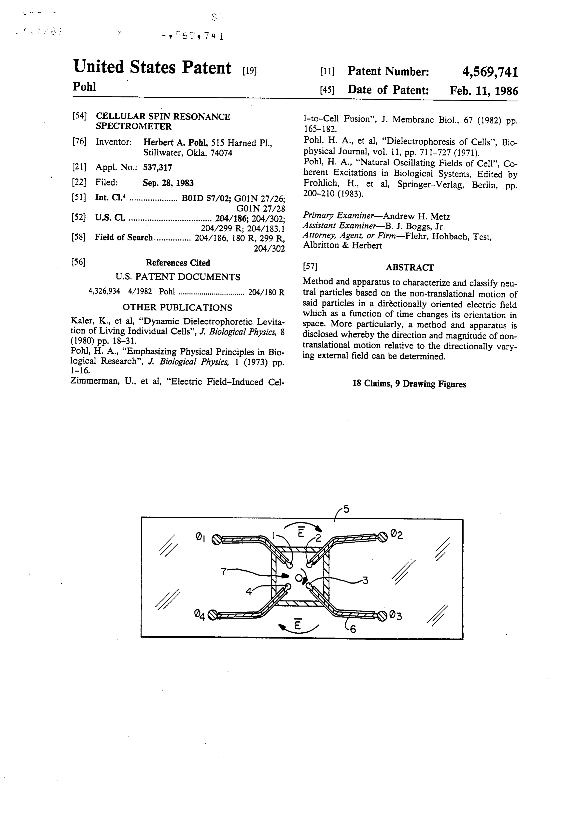
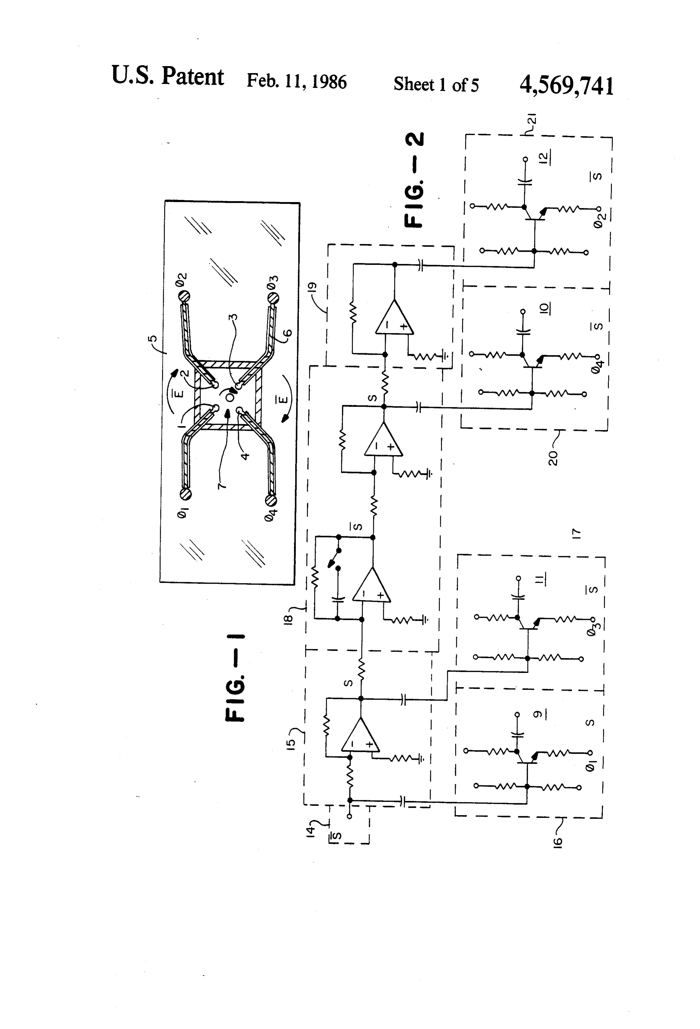
animate and over a wide range, inanimate neutral cells at the two electrodes producing the AC field was particles with regular or irregular shape can be deter the predominant phenomenon observed. While so stacked, it was noted that occasionally individual cells mined by use of the present invention. would rotate about an axis perpendicular to the applied BRIEF DESCRIPTION OF THE DRAWINGS field lines. The cells rotated at a rate of several revolu 25 tions per second in response to an AC field frequency in FIG. 1 illustrates a four-electrode embodiment used the range of 102-106 Hz. This rotational phenomenon to FIG. generate a circularly rotating electric field. was found to be dependent upon the frequency of the generate2aiscircularlya schematic diagram of the circuitry used to rotating electric field.
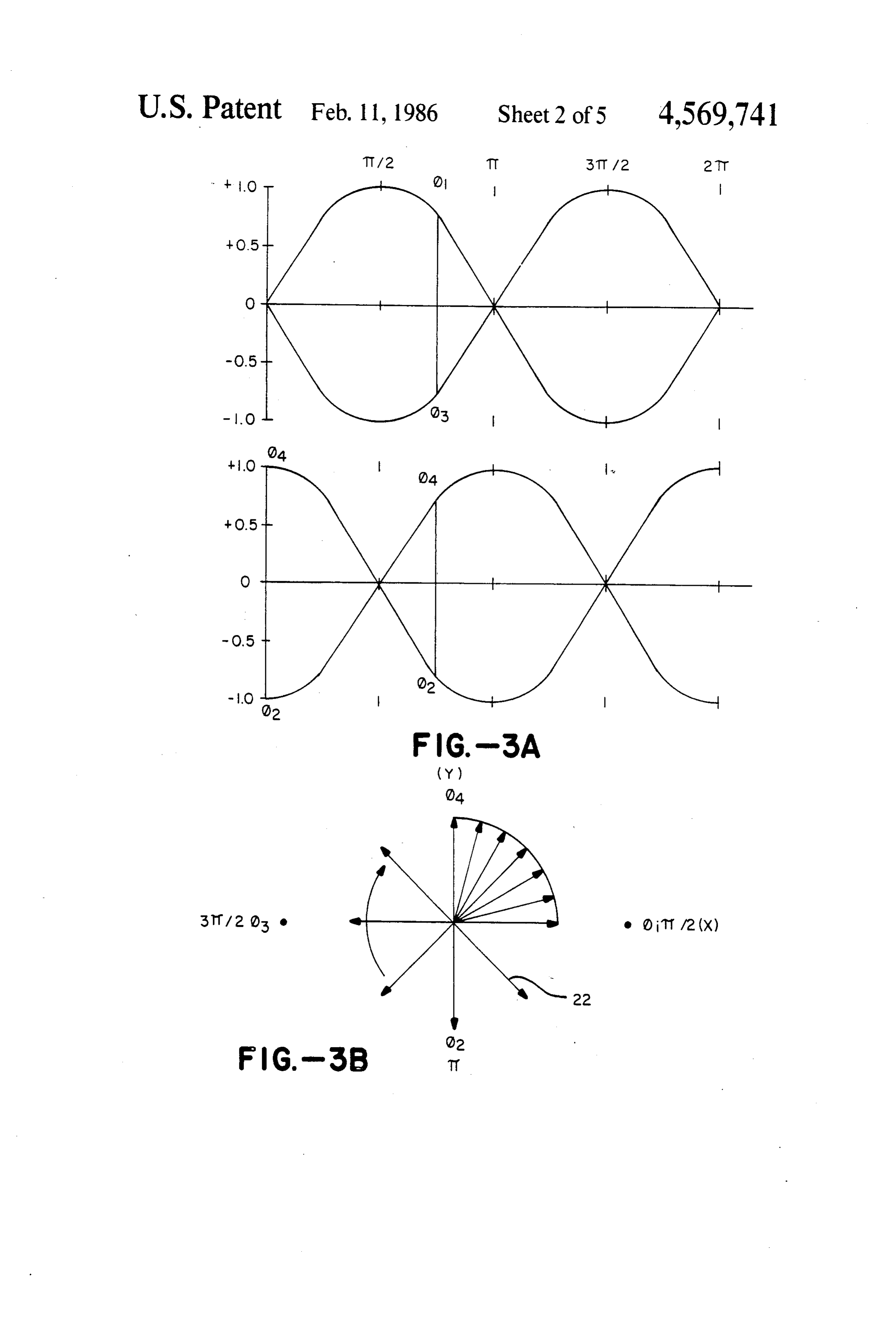
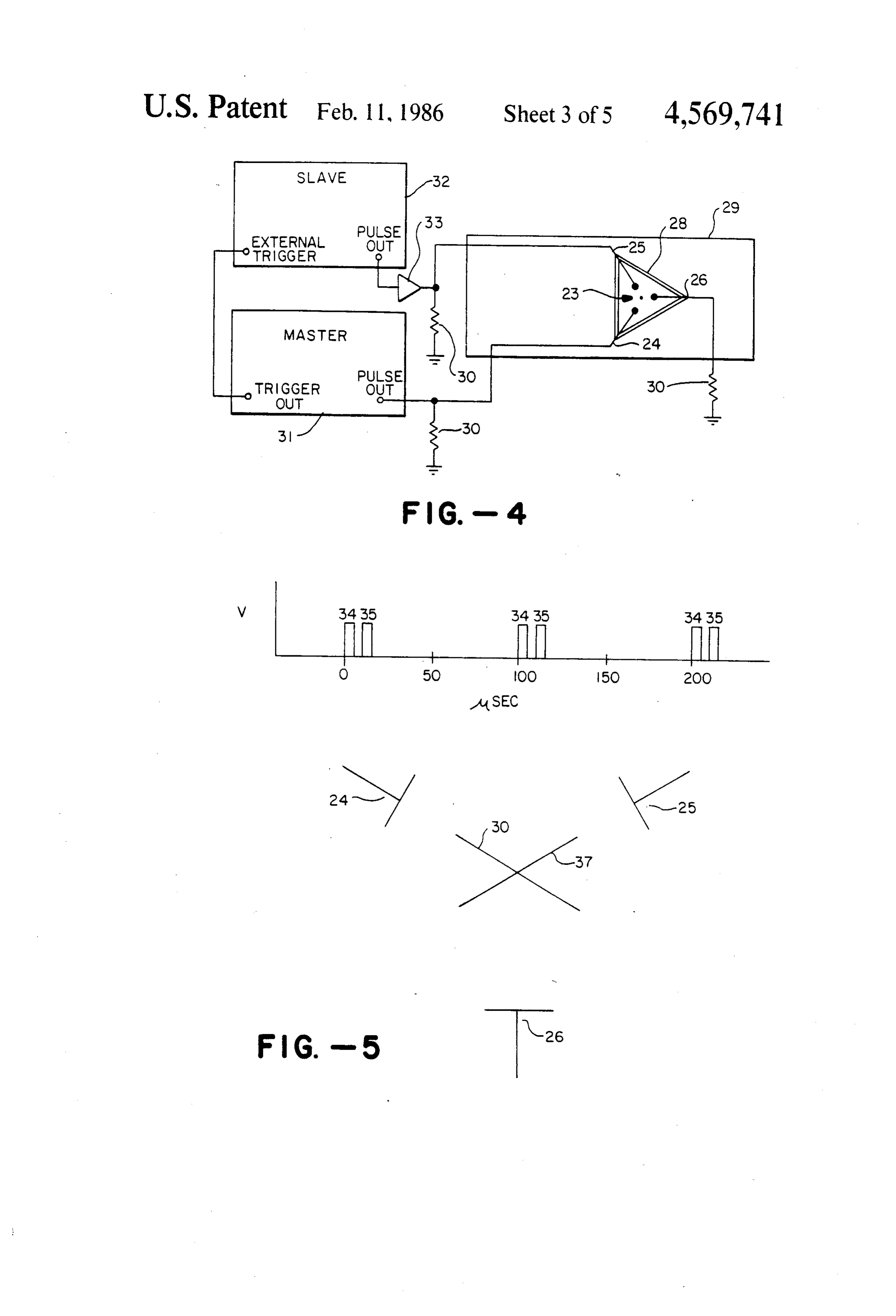
external AC field. As the frequency of the applied field was varied individual cells within the stacks of cells at circularly rotating field. wave forms used to generate a 30 FIG. 3 illustrates the the electrodes were observed to start and stop their rotational motions over a relatively narrow frequency FIG. 4 illustrates a two-pulse three-electrode embodi range. These observations gave rise to the term cellular ment for generating pulsed rotating fields. spin resonance (CSR) to describe this phenomenon. FIG. 5 illustrates a pulsed DC wave form and the In addition to the cellular rotation observed in stacks 35 electric field generated in a two-pulse three-electrode of cells, lone single cells were occasionally observed to embodiment.
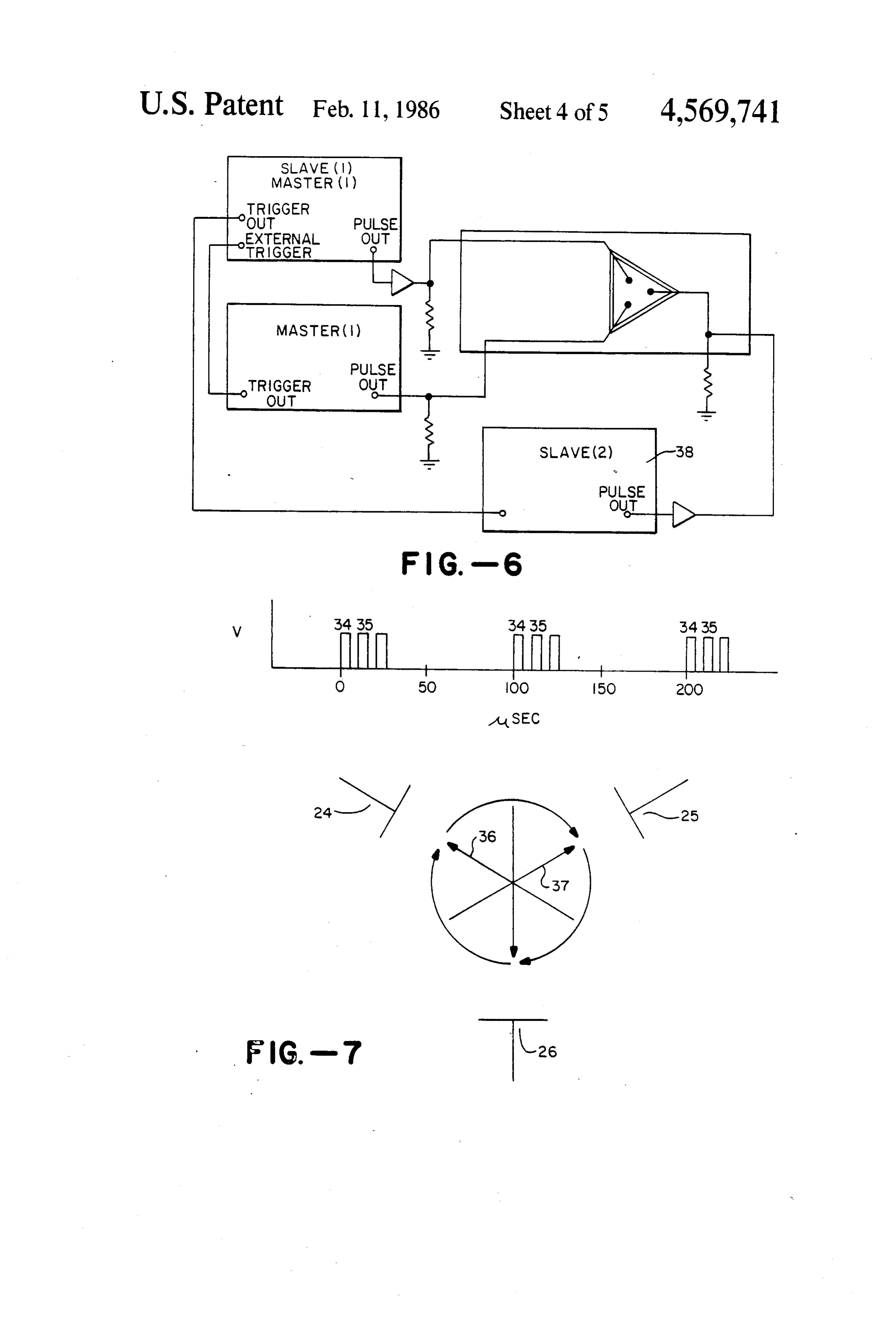
demonstrate the same phenomenon. The frequency of FIG. 6 illustrates a three-pulse symmetrical three such a response for live single cells was, however, dis electrode embodiment.
tinctly different from that observed for cells stacked at FIG. 7 illustrates the pulsed DC wave form and re the electrodes. Observation of single cells was, how sulting electric fields in a three-pulse symmetrical three ever, hampered by the translational motion of such cells electrode embodiment.
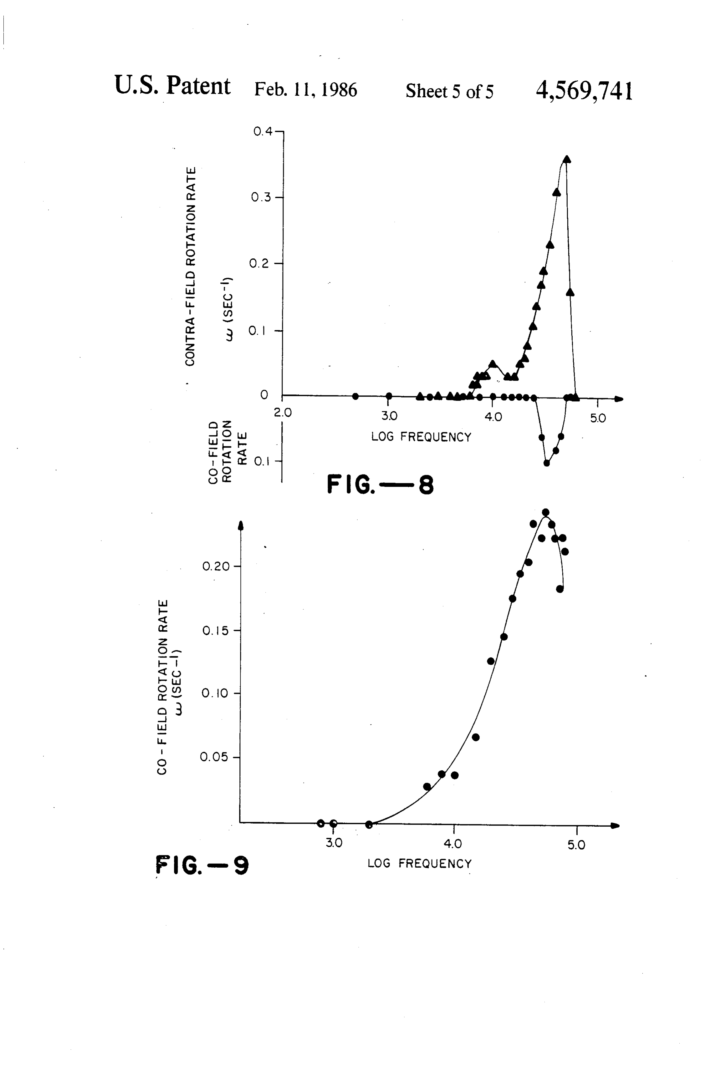
toward the electrodes due to dielectrophoretic forces. FIG. 8 is the CSR spectrum for individual yeast cells The observed phenomenon has been found to be exposed to a circularly rotating electric field. dependent upon the conductivity of the medium, the FIG. 9 is the CSR spectrum for barium titanate. intensity of the applied field, with the cell type, with the 45 SUMMARY OF THE INVENTION phase of the cell life cycle, and the presence of trace chemicals which affect cells. In addition, it has been In general, the invention consists of means and meth postulated that the rotation of live single cells is, at ods for observing non-translational motion of neutral times, due to the interaction of a natural cellular dipole particles in a directionally orientated electric field oscillation and the applied field. Natural Oscillating 50 which as a function of time changes its orientation in Fields of Cells by Herbert A. Pohl in Coherent Excita space.
tions in Biological Systems Ed by H. Fröhlich and H. The change in electric field vector orientation can be Kremer; Springer Verlag, N.Y. (1983) pgs. 227-238. continuous or pulsed. If continuous, the electric field Other phenomena associated with cells which as yet are vector can be made to assume a continuous circular unknown may also contribute to non-translational mo 55 rotation. If pulsed, the electric field vector can be made tion. Exposure to complex electric fields may be impor to sequentially assume discrete pre-defined spatial ori tant in the further characterization of cellular phenome entations. The net effect of either the continuous or
pulsed change in the electric field orientation is to pro
The characterization of the non-translational motion duce an electric field which rotates in either a clockwise of neutral particles has heretofore been limited to the or counter-clockwise direction.
measurement of the frequency at which rotation is ob Generally, rotating electric fields are generated by served and by a general description that such rotation applying pulsed DC or continuous AC electric fields to occurs about an axis perpendicular to the applied elec an array of electrodes. The number and orientation of tric field. In addition, detailed and continuous observa these electrodes can be varied but typically three or tion of single neutral particles has been hampered by 65 four electrodes are positioned symmetrically with re dielectrophoretic translational motion. The need there spect to each other. The details of the invention will be fore existed for an apparatus and method which would disclosed in the description of the preferred embodi allow a more refined study of the observed phenome ment.
Page 8
The present invention seeks to facilitate and advance known to those within the art which will provide a the use of the CSR phenomenon. Accordingly, an ob signal in the frequency range of interest. The inverter ject of the present invention is to provide methods and circuits 15 and 16 are exemplary of many possible con means to characterize neutral particles based on the figurations which can produce the desired results. The non-translational motion of said particles in a direction output from terminal 9 is inverted with respect to the ally oriented field which varies its orientation with time. original signal from oscillator 14. Power inverter 15 A further object of the present invention is to provide maintains signal amplitude and generates an inverted methods and means to determine the direction of the signal which is applied to inverter 17 and the adjustable non-translational motion of neutral particles relative to phase delay circuit 18. Inverter 17 is essentially identical the movement of an applied electric field. 10 to inverter 16. The output from terminal 11 is inverted A further object of the present invention is to provide with respect to the output from terminal 9. methods and means to characterize the non-transla tional motion of neutral particles in a circularly rotating the outputdelay
Phase
circuit 18 inverts the signal twice so that inverted with respect to the original oscil electric field. lator signal. The primary purpose of circuit 18 is to A further object of the present invention is to provide 5 provide means for generating a signal which is out of methods and means for enhancing the observation of phase with respect to the original input. For the purpose the phenomenon described herein by minimizing the of generating a circularly rotating field this phase angle translational motion of neutral particles due to dielec should be 90'. Circuit 18 also provides means for main trophoretic forces. taining the circularity of the applied field by compensat A further object of the present invention is to provide 20 ing for frequency dependent phase delays and imperfect methods and means for determining dielectric constants electrode alignment. Power inverter 19 and inverters 20 over a wide frequency range for animate and inanimate and 21 are substantially identical to circuits 15, 16 and neutral particles which is relatively unaffected by the 17 and are similarly arranged.
regular or irregular shape of the neutral particles. FIG. 3A is a graphic representation of the output Additional objects and features of the invention will 25 signals from terminals 9, 11, 10 and 12 and are desig be evident from the following description of the pre nated respectively d1, db3, d4 and d2. The subscripts ferred embodiments taken in conjunction with the ac indicate the electrode which receives that particular companying drawings. signal. The sinusoidal output of db and d3, are in phase DETAILED DESCRIPTION OF THE but inverted with respect to each other. The output of 30 d4 and d2 are similarly related but are 90' out of phase
PREFERRED EMBODIMENT
with respect to d1 and d3.
A preferred embodiment of the present invention is FIG. 3B illustrates the circularly rotating electric presented in FIG. 1 and FIG. 2. In FIG. 1 four platinum field 22 produced by signals d1 and d2, d3 and d4 when wires of approximately 75 micron-diameter having applied to electrodes 1, 2, 3 and 4. As depicted the smoothly rounded tips which are approximately 130 35 direction of rotation is clockwise. The rotation direc microns in diameter act as electrodes 1, 2, 3 and 4. The tion can, however, be reversed by shifting the phase platinum wires are approximately one centimeter long relationship between d1-db3 and d2-dba by 180'. and are arranged on a glass microscope slide 5 in the The circularly rotating field depicted in FIG. 3B is form of a cross with a square centered gap. The distance one of many types of fields which may be used with the between opposing electrode tips is approximately 1.2 invention. In practicing the invention, those skilled in millimeters. The platinum wires are partially covered the art can readily devise means for generating more by an insulating length of teflon tubing 6 which extends complex fields to explore the mechanism of the ob nearly to the tips of the electrodes 1, 2, 3 and 4. Cham served phenomenon and to further categorize neutral ber 7 is defined by plastic walls 8 which can be made of particles. An example of such a field would be the su polyethylene or any other appropriate material. The 45 perposition of a variable frequency oscillation on the walls 8 are approximately one millimeter thick and are rotating electric field. Since the phenomenon of CSR is positioned to produce a chamber 7 which is approxi a recent discovery, the types of fields which may ulti mately 8.2 millimeters in width and height. The walls 8 mately be used for the present invention cannot be spe and electrodes 1, 2, 3 and 4 with teflon tubing 6 are cifically described. The present invention contemplates, attached to the glass microscope slide 5 by an appropri 50 however, the use of any fields which induce non-tran ate cement, for example, epoxy cement. The positioning slational motion in neutral particles and should not be of the components described and the cementing of said restricted to the fields herein described. parts provides a chamber which is capable of containing FIG. 4 illustrates a second embodiment of the inven a liquid suspension of neutral particles without substan tion. The materials used in constructing the triangular tial leakage. The platinum wires which lead to elec 55 chamber 23 are substantially the same as those used in trodes 1, 2, 3 and 4 are cemented to leads going to the the four electrode apparatus depicted in FIG. 1. Three output terminals 9, 10, 11 and 12 of the rotating field teflon-coated platinum electrodes 24, 25 and 26 are circuit 13 in FIG. 2 by connectors 14 which can be mounted together with plastic walls 28 on glass micro Cu-Pt junctions cemented by silver paste or any other scope slide 29 to form a triangularly centered gap. Each appropriate connectors known to those in the art. The electrode is grounded through an appropriate resistor platinum electrodes 1, 2, 3 and 4 are connected to the 30. Master unit 31 is a pulse source which can generate output 9, 10, 11 and 12 of FIG. 2 in the following man DC pulses over a frequency range of interest. The out
The preferred basic circuitry 13 for generating the put for master unit 31 is applied to electrode 24. Slave unit 32 is a DC pulse generator which is activated by circular rotating field is shown schematically in FIG. 2. 65 the trigger output of master unit 31. Slave unit 32 con The input from oscillator 14 is applied to power in tains circuitry which allows the DC output of generator verter 15 and inverter 16. Oscillator 14 can be an H-P 32 to be delayed. The output from generator 32 is ap 200 CD oscillator or any other appropriate source plied to electrode 25. If necessary, the amplitude of the
Page 9
signal can be regulated by amplifier 33. Master unit 31 the rotating electric field. This is consistent with the may be a H-P pulse generator model 214A with a fre theory proposed by Pohl. cf. Pohl, H. A. Cellular Spin quency range of 10 KHz to 100 KHz or other appropri Resonance in Rotating Electric Fields, Int. J. Quantum ate pulse source while slave unit 32 can be a Rutherford Chem. (1983) in press.
Electronics Company, B16 pulse generator. Having described the preferred embodiment of the FIG. 5A illustrates the DC pulses generated as a present invention, it will occur to those skilled in the art function of time when a 5 micro second 10 KHz signal that various modifications and alterations can be made is generated by master unit 31 and the time delay in to slave unit 31 is 10 micro seconds. As illustrated, pulse 34 thethe disclosed embodiments without departing from spirit of the invention.
is applied to electrode 24 and pulse 35 is applied to O The following claims define the scope of the inven electrode 25. As illustrated in FIG. 5B, pulses 34 and 35 tion:
produce electric fields 36 and 37 respectively. The af. What is claimed is:
fect of the sequential application of the DC pulses to the different electrodes is the production of a rotating elec on1.theA induced method for characterizing neutral particles based non-translational motion of said particles tric field with discreet pre-defined spatial orientations. 15 by an electric field comprising, FIG. 6 shows the same basic apparatus as that of FIG. generating a directionally orientated electric field 4 except for the addition of a second slave unit 38. Slave unit 38 is a pulse DC generator driven by slave unit 32. wherein the orientation of said field in space has The output from unit 38 is applied to electrode 26. FIG. more than two directly opposite orientations and 7 illustrates that the DC pulse pattern and electric field 20 said orientation varies as a function of time, vectors produced in this embodiment. exposing one or more neutral particles to said field, and
As discussed in conjunction with the four electrode apparatus of FIG. 1, it is contemplated that a variety of determining the direction of the induced non-transla electric fields will be applied to these three electrode tional motion of said particle relative to said field. embodiments. 25 2. A method according to claim 1 wherein said non It is also contemplated that the invention is not lim translational motion is rotation.
ited to the three electrode and four electrode embodi 3. A method according to claim 1 where said non ments described. Any two or three dimensional combi translational motion is libration.
nation of electrodes which can be used to generate 4. A method according to claim 1 where said electric electric fields that induce non-translational motion in 30 field is circularly rotating.
neutral particles is contemplated by the invention. 5. A method according to claim 4 where said circu
EXAMPLE 1.
larly rotating field is generated by the application of four sinusoidal fields to four symmetrically arranged
Yeast cells (Saccharomyces cerevisiae) were grown at electrodes said fields being related such that the fields 25 C. in sterile Saboraud Liquid Medium (Difco) for 35 applied to opposing electrodes are 180° out of phase seven days. The cells were harvested by centrifugation with respect to each other and such that the fields ap and repeatedly washed with de-ionized water until the plied to adjacent electrodes are 90 out of phase with overall resistivity of the suspension was at least 200 respect to each other.
Kohn-cm. A drop of cell suspension was placed in the 6. A method according to claim 1 where said electric chamber well of the four electrode apparatus and cov field is sequentially pulsed to generate directionally ered with a microscope cover slip. The cells were ob discrete electric fields.
served through a microscope with 400X magnification. 7. A method according to claim 1 where said electric The suspension was exposed to a circularly rotating field has a rotational component and an oscillating com electric field (10 volts p-p) at frequencies ranging from ponent.
500 to 75,000 Hz. The rate of rotation for individual 45 8. A method according to claim 1 where said neutral cells was measured at different frequencies. The proce particles are derived from biological systems. dure was repeated on a suspension of dead cells which 9. A method according to claim 1 where said neutral were heat-killed by exposure to 70° C. for three min particles are inanimate.
utes. 10. An apparatus for characterizing neutral particles FIG. 8 is the CSR spectrum derived from this experi 50 comprising, ment. As can be seen the live cells rotate in a contra means for generating a directionally oriented electric field direction and exhibit two response regions. Dead field wherein said field has more than two directly cells, on the other hand, have only one response region opposite orientations which vary with time and and rotate in the same direction as the applied field. means for detecting the direction of induced non EXAMPLE 2 55 translational motion of said neutral particles rela tive to said field.
Barium titanate powder was ground in a mortar and 11. An apparatus according to claim 10 where said pestle. The powder was subsequently graded by size to non-translational motion is rotation. provide particles of 1.5-3.0 micron diameter. This was 12. An apparatus according to claim 10 where said achieved by sedimentation followed by successive fil non-translational motion is libration. tration through Nucleopore filters of 3 and then 2 mi 13. An apparatus according to claim 10 where said cron pore diameter. The particles were suspended in electric field is circularly rotating.
0.01% soluble potato starch to stabilize the suspension. 14. An apparatus according to claim 13 where said The resistivity of the suspension was 86 Kohm-cm circularly rotating field is generated by the application when analyzed in the four electrode apparatus. 65 of four sinusoidal fields to four symmetrically arranged The results of that experiment are shown in FIG. 9. electrodes said fields being related such that the fields As can be seen, highly polarizable inanimate particles applied to opposing electrodes are 180° out of phase such as barium titanate rotate in the same direction as with respect to each other and such that the fields ap
Page 10
plied to adjacent electrodes are 90 out of phase with electric field has a rotational component and an oscillat respect to each other. ing component.
15. An apparatus according to claim 10 where said 17. An apparatus according to claim 10 where said - o neutral particles are derived from biological systems. electric field is sequentially pulsed to generate direc- 5 18. An apparatus according to claim 10 where said tional discrete electric fields. neutral particles are inanimate. 16. An apparatus according to claim 10 where said it x x k
Provenance
- Collection
- Cited prior art
- Original PDF
- patentimages.storage.googleapis.com →
- Filed
- 1983-09-28
- Pages
- 10
- Method
- pdftotext (the PDF's own text layer) + pdftoppm 300dpi page scans
- Source
- Google Patents bibliographic record
- Granted
- 1986-02-11
- Inventors
- Herbert A. Pohl
- Transcribed from
- patentimages.storage.googleapis.com →