patent · US4815433
Method of and device for controlling and/or regulating the idling speed of an internal combustion engine
28 March 1989
Page 1 — bibliographic record
United States Patent (19) 11) Patent Number: 4,815,433 Wild 45 Date of Patent: Mar. 28, 1989 54 METHOD OF AND DEVICE FOR 56) References Cited CONTROLLING AND/OR REGULATING U.S. PATENT DOCUMENTS
THE DLING SPEED OF AN INTERNAL
COMBUSTION ENGINE 4,305,360 12/1981 Meyer et al......................... 123/339
75 Inventor: Ernst Wild, Weissach, Fed. Rep. of 4,567,869 2/1986 Peter et al. . 123/339 Germany 4,597,047 6/1986 Deutsch ...... ... 123A339
73) Assignee: Robert Bosch GmbH, Stuttgart, Fed. Primary Examiner-Andrew M. Dolinar Rep. of Germany Attorney, Agent, or Firm-Michael J. Striker
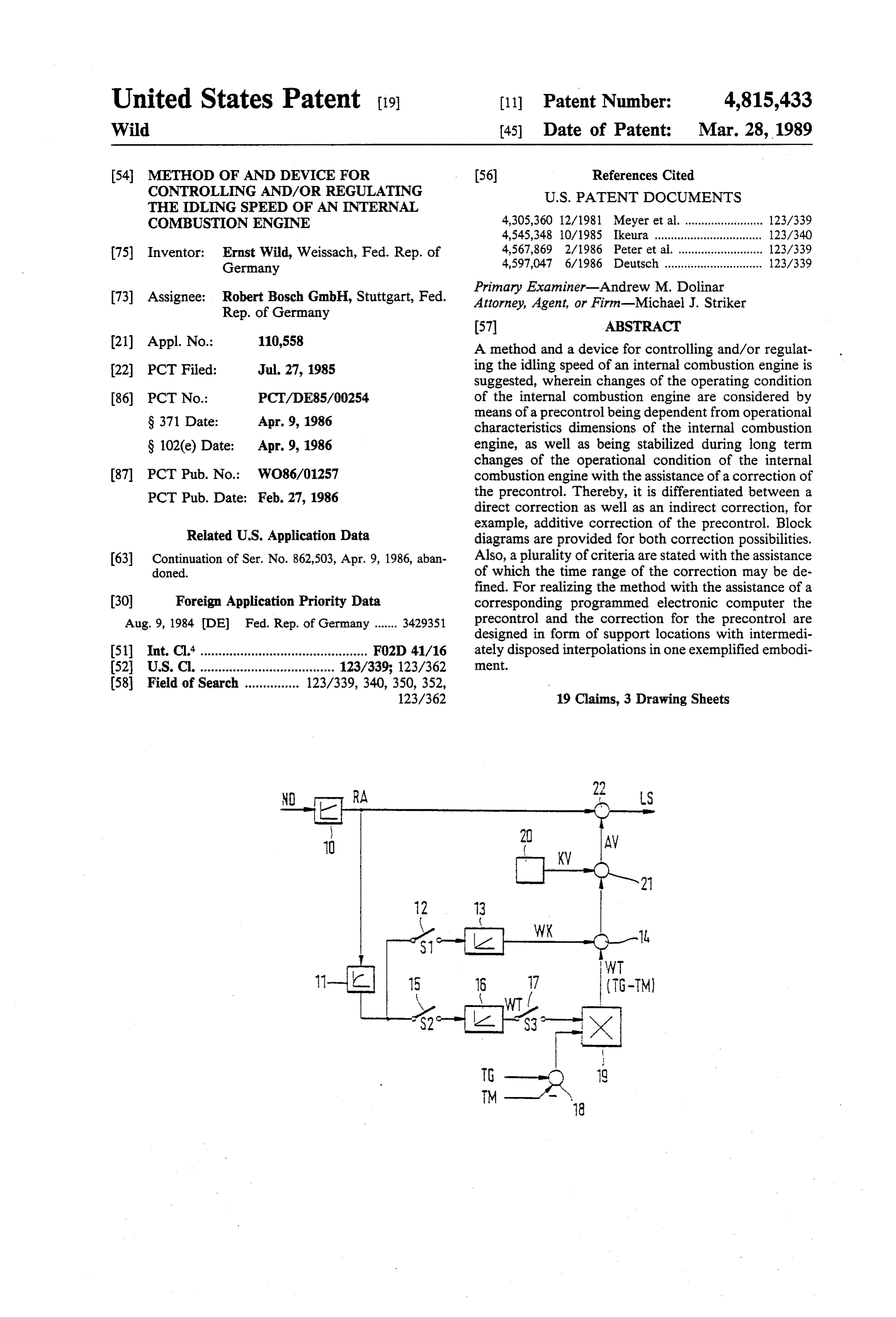
21 Appl. No.: 110,558 A method and a device for controlling and/or regulat 22, PCT Filed: Jul. 27, 1985 ing the idling speed of an internal combustion engine is suggested, wherein changes of the operating condition 86) PCT No.: PCT/DE85/00254 of the internal combustion engine are considered by means of a precontrol being dependent from operational
S371 Date: Apr. 9, 1986 characteristics dimensions of the internal combustion S 102(e) Date: Apr. 9, 1986 engine, as well as being stabilized during long term changes of the operational condition of the internal 87 PCT Pub. No.: WO86/01257 combustion engine with the assistance of a correction of PCT Pub. Date: Feb. 27, 1986 the precontrol. Thereby, it is differentiated between a direct correction as well as an indirect correction, for example, additive correction of the precontrol. Block
Related U.S. Application Data diagrams are provided for both correction possibilities. 63 Continuation of Ser. No. 862,503, Apr. 9, 1986, aban Also, a plurality of criteria are stated with the assistance doned. of which the time range of the correction may be de fined. For realizing the method with the assistance of a 30 Foreign Application Priority Data corresponding programmed electronic computer the Aug. 9, 1984 DE Fed. Rep. of Germany ....... 3429351 precontrol and the correction for the precontrol are designed in form of support locations with intermedi 51 Int. Cl." .............................................. FO2D 41/16 ately disposed interpolations in one exemplified embodi 52 U.S.C. ..................................... 123/339; 123/362 ment.
Page 2
Drawing sheet — no readable text.
Page 3
Drawing sheet — no readable text.
Page 4
Drawing sheet — no readable text.
Page 5
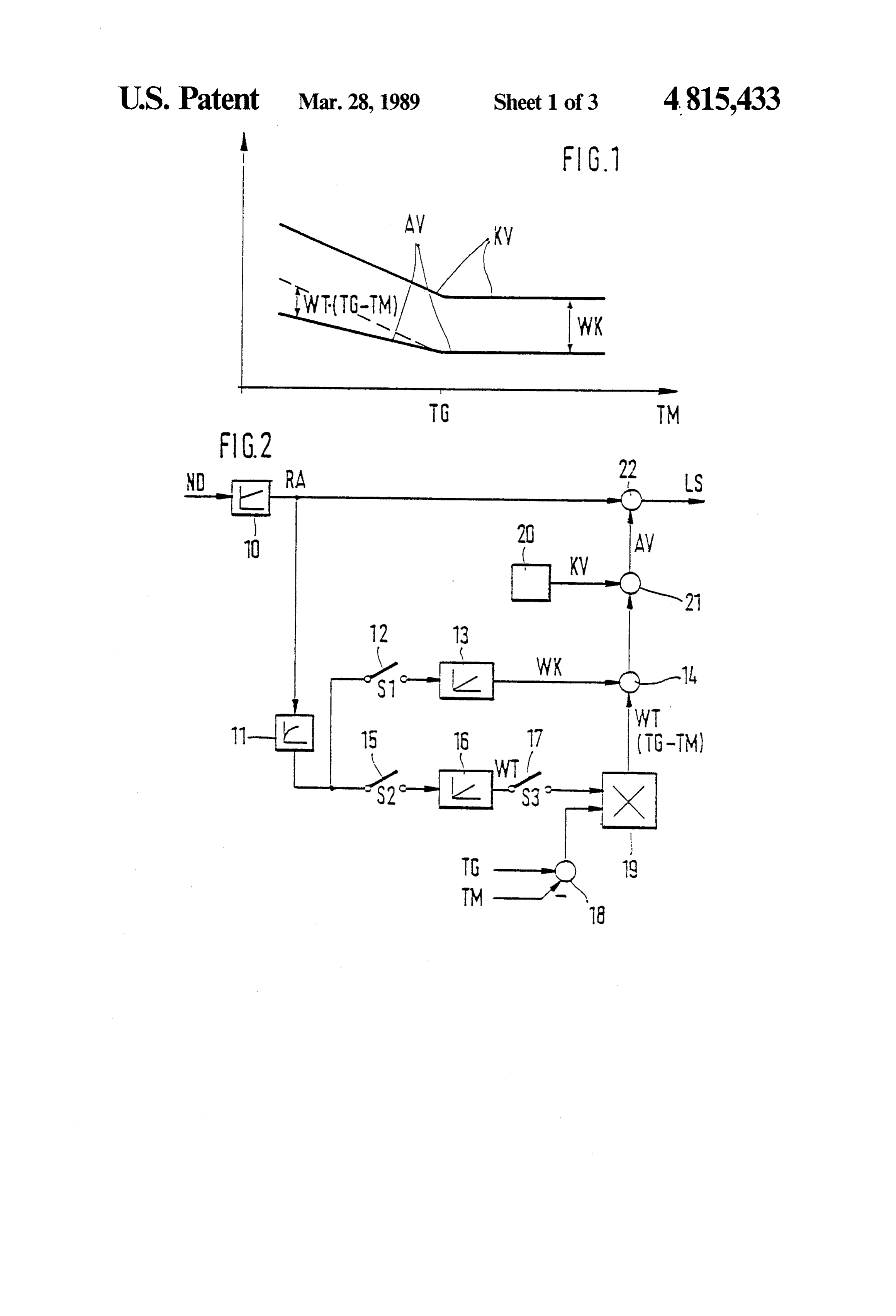
METHOD OF AND DEVICE FOR CONTROLLING BRIEF DESCRIPTION OF THE DRAWINGS AND/OR REGULATING THE IDLING SPEED OF FIG. 1 illustrates an indirect correction of the pre AN INTERNAL COMBUSTION ENGINE control of the idling speed of an internal combustion 5 engine;
This application is a continuation of application Ser. FIG. 2 is a schematic diagram of the realisation of the No. 862,503, filed Apr. 9, 1986, now abandoned. indirect correction of FIG. 1;
BACKGROUND OF THE INVENTION
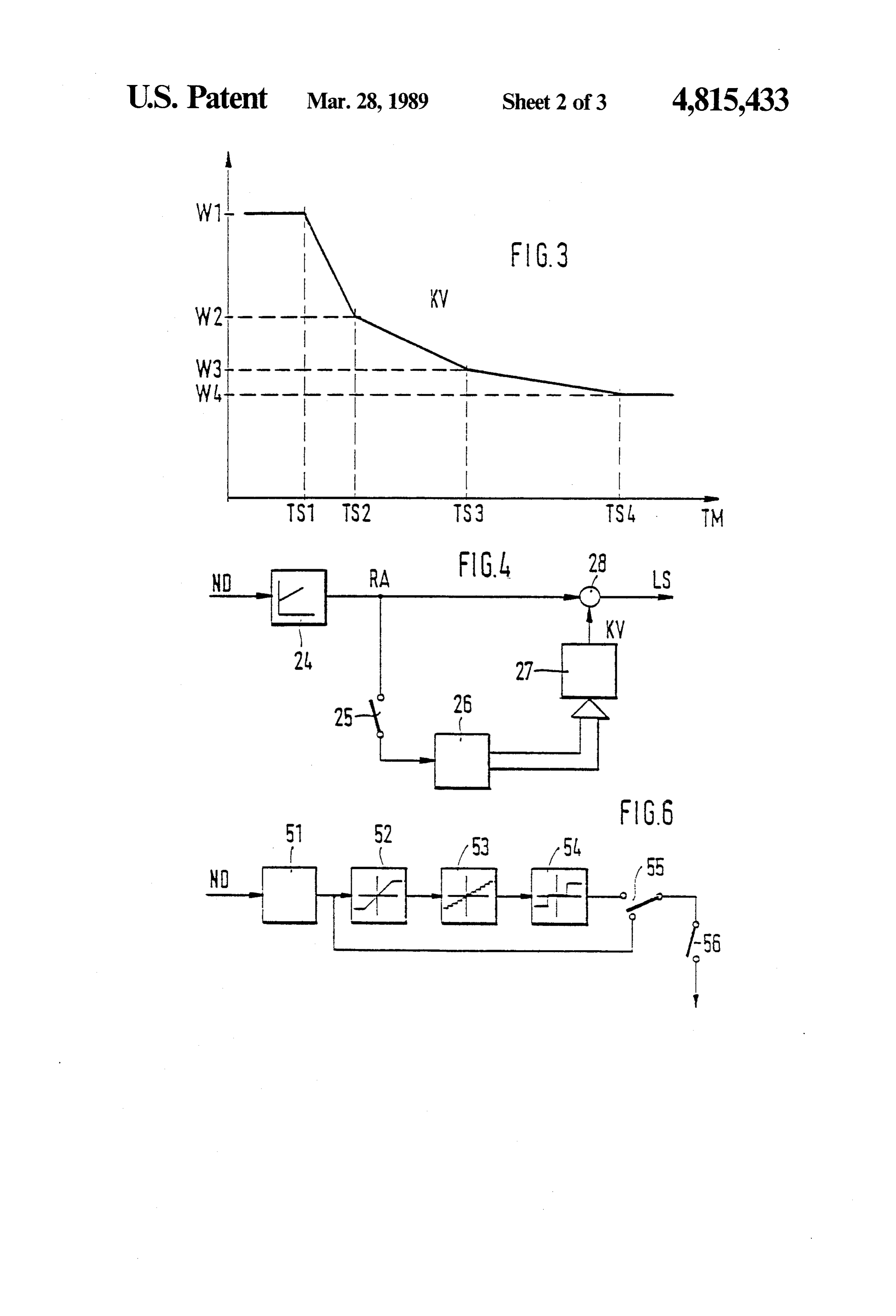
FIG. 3 is a graph showing a direct correction of the precontrol of the idling speed regulation of an internal
The invention relates to a method and a device for O combustion engine;
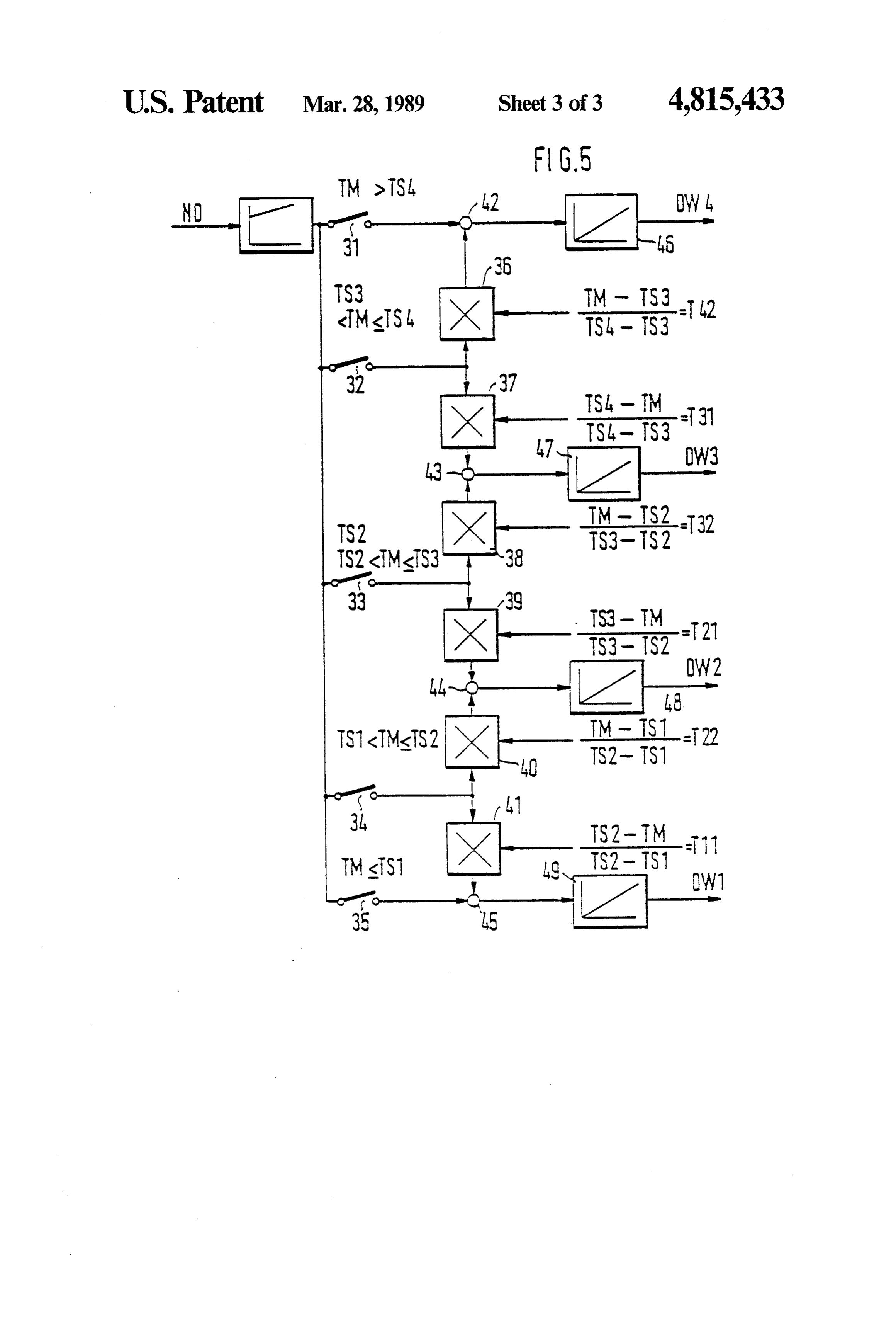
controlling and/or regulating the idling speed of an FIG. 4 is a schematic diagram of the realisation of the internal combustion engine. direct correction of FIG. 3; It has been known to take into consideration the oper FIG. 5 is a schematic diagram illustrating the correc ating state of an internal combustion engine for regulat tion device of FIG. 4 and ing the idling speed. The regulation of the idems speed 15 FIG. 6 is a schematic diagram of a further embodi has been performed, for example, by determines idling ment of the precontrol of the idling speed of an internal speed values for defined operating conditions of the combustion engine.
internal combustion engine and regulating the speed of DETAILED DESCRIPTION OF THE the internal combustion engine based on these predeter 20 PREFERRED EMBODIMENTS mined values. Generally, with the assistance of the
The described exemplified embodiments relate to the known precontrols it has been possible to quickly stabi control lize changes in the operating state of the internal com internal and/or the regulation of the idling speed of an bustion engine, for example, the load change of the can be generally usedengine.
combustion This idling speed regulation internal combustion engine during switching on an air 25 bustion engines, that is,in inconjunction with internal com conjunction with Otto-inter conditioning unit, for example, during the regulating of the idling speed of the internal combustion engine. nal combustion engines, with Diesel-internal combus With each internal combustion engine not only short tion engines, etc. Also, the exemplified embodiments term changes in the operational state occur, like, for described circuit herein below are not limited to any specific arrangements, but they can be realized in any example, the mentioned load jump during the switching 30 embodiment being obvious on of the air conditioning unit, but the operational state for example, in the analogtoora person digital skilled in the art, shifting control of the internal combustion engine also causes long term technique with the assistance of a correspondingly pro changes. Such long term changes are mostly caused by grammed microcomputer, etc.
aging effects of the total internal combustion engine. FIG. 1 illustrates an indirect correction of the pre These long term changes have not taken into consider 35 control of the idling speed regulation of an internal ation in the known idling speed regulating, conse combustion quently, the idling speed could not been regulated to trated on theengine. The motor temperature TM is illus optimal values for a long term by the known idling the limit temperature Taiaxis horizontal of the diagram, whereby is particularly shown on this speed regulator, so that the transmissions to the idling axis. This limit temperature TG is the motor operating speed were performed with higher or lower oscillations temperature of the internal combustion engine during of the speed of the internal combustion engine. normal operation. The characteristics curves illustrated SUMMARY OF THE INVENTION in the diagram are a performance graph-precontrol signal KV, on the one hand, and an adapted precontrol
In is an object of this invention to provide an im signal AV, on the other hand. The constant distance proved method and device for controlling the idling 45 between the performance graph precontrol signal KV speed of an internal combustion engine. and the adapted precontrol signal AV is illustrated in In contrast to the above described conventional the diagram of FIG. 1 by the constant value WK. The methods the method for controlling and/or regulating deviation of the adapted precontrol signal AV from the the idling speed of an internal combustion engine ac performance graph precontrol signal KV from the con cording to the invention is advantageous in that long 50 stant value WK is illustrated in the diagram of FIG. 1 term changes of the operational state of the internal by the value WT (TG-T) wherein WT designates a combustion engine can be considered during the regula temperature dependent value, while To, as already tion of the idling speed of the internal combustion en stated, the limit temperature, and TM represents the gine due to the correction of the precontrol of the idling motor temperature.
speed regulation which is dependent from the opera 55 The performance graph precontrol signal KV illus tional state of the internal combustion engine. trated in the diagram of FIG. 1 is a signal which is In accordance with the invention two possibilities of stored in any given form in a storage and whose size the correction of the precontrol of the idling speed depends from the operational state of the internal com regulation of the internal combustion engine are pro bustion engine. For example, if the operational state of vided, namely the direct correction, that is, the change the engine is changed by switching on the air condition of the precontrol values themselves or the indirect cor ing unit, the performance graph precontrol signal rection, that is, the change of the precontrol values by changes simultaneously with this change. The desired the addition of correcting values. idling speed of the internal combustion engine is more Generally, the method in accordance with the inven rapidly reached with the assistance of the performance tion provides an optimal building up of the speed of the 65 graph precontrol signal K.V. The heretofore described internal combustion engine into the idling speed, for operations are known. The long term changes of the example, from the operational conditions with the par operational state of the internal combustion engine can tial load or the switching off signal. be considered by the precontrol if the adapted precon
Page 6
trol signal AV is used according to the subject inven the precontrol performance graph 20, which is desig tion for the idling speed regulation in place of the per nated with KV, are connected to connecting location formance graph precontrol signal KV. This adapted 21. In dependency from its input signals the connecting precontrol signal AV results from the graph perfor location 21 forms an output signal AV fed to the con mance precontrol signal in accordance with the dia 5 necting location 22. This connecting location 22 finally gram of FIG. 1 due to the following two equations: forms from their input signals the output signal LS AW-e KV-- WK-- WT(TG-T) for TMsTG which is an idling speed set signal.
and With the assistance of the block diagram of FIG. 2 it is possible to realise the displacement of the perfor 10 mance graph precontrol signal KV toward the adapted
AV's KV-- WK for TTG.
Accordingly, the performance graph precontrol sig precontrol signal AV illustrated in FIG. 1. The values nal KV is displaced above the limit temperature To by WK and WT which determine this displacement are the constant value WK toward the adapted precontrol dependent from the control output signal RA, as well as signal AV, while the performance graph precontrol from the switch positions of the two switches 12 and 15. signal KV is displaced below the limit temperature To 15 The two values WK and WT are intermediately stored not only by the constant value WK, but also simulta by means of the two integrators 13 and 16. neously its gradient is changed in dependency from the The switch S1 closes when the internal combustion temperature dependent value WT. The constant value engine is in its disconnected state and when the motor WK and the temperature dependent value WK may be temperature TM is greater than the limit temperature positive or negative values. TG. The disconnected state of the internal combustion The change of the performance graph precontrol engine can be determined, for example, in that the total signal KV towards the adapted precontrol signal AV, of the speed differential signals ND is smaller than a illustrated in the diagram of FIG. 1, is only one possibil defined, predetermined speed differential threshold and ity of such a change. In accordance with the invention that also the control output signal RA is smaller than a it is also possible to change the performance graph 25 defined, predetermined control output threshold. When precontrol signal KV toward the adapted precontrol the switch S1 is closed, also when TM). TG is in the signal AV in any given manner, for example, by a paral decoupled state, it means that the performance graph lel displacement of KV toward AV over the total range precontrol signal KV of the precontrol performance of the motor temperature TM. With such an exemplified graph 20 is only corrected by signal WK acting through simplification of the diagram of FIG. 1, there are corre 30 switch S1. Generally in this state AV =KV--WK, as sponding resulting simplifications of the realisation of stated in the description with respect to FIG. 1. the diagram of FIG. 1 (FIG. 2). Switch S2 closes exactly when the internal combus FIG. 2 illustrates a realisation of the indirect correc tion of FIG. 1. An idling speed regulator is designated tion engine is in its uncoupled state and when the motor temperature TM is smaller than the limit temperature
with reference numeral 10 and has an integral compo To. This means nent. The reference numeral 11 indicates a low pass. WT changes onlythat the temperature dependent value when switch S2 is closed. The output
The switch S1 is designated with the reference numeral signal of the multiplicator 19 cannot supply an output 12 and the switch S2 with the reference numeral 15.
signal because of the closing
One integrator is designated with the reference numeral switch S3 is closed, the multiplicator of switch S2. Only when 13 and the other integrator-with the reference numeral put signal which is uneven zero. Switch generates an out 16. The reference numeral 17 denotes switch S3. Con S3 is closed necting locations are designated with the reference exactly when the motor temperature TM is smaller than numerals 14,18, 21 and 22. A multiplicator is designated the limit temperature TG independently from the other with the reference numeral 19. Finally, a precontrol condition of the internal combustion engine. Generally performance graph is designated with the numeral ref. 45 this means that a signal is available at the output of the erence 20. The idling speed regulator 10 forms a control multiplicator 19 when the switch S3 is closed, having output signal RA in dependency from its input signal the value WT (TG-TM). When switch S2 is opened, which is a speed differential signal ND. The output this value changes only in dependency from the limit signal RA is then fed to the low pass 11, on the one temperature Tog and the motor temperature T.M. If hand, and to the connecting location 22, on the other 50 switch S2 is closed, the output signal of the multiplica hand. The low pass 11 forms an output signal dependent tor 19 changes also independency from the temperature from signal RA, which is fed to the two switches 12 and dependent value WT. When switch S3 is closed the 15. Each integrator 13, 16 is switched subsequent to following equation prevails for the adapted precontrol each of the two switches, that is, the integrator 13 to signal: AV =KV-WK--WT (TG-TM), as has been switch 12 and the integrator 16 to switch 15. On the one 55 described in conjunction with the description of FIG. 1. hand, switch 17 is connected with the output of the Not only the temperatures Tc, and TM can change on integrator 16 and, on the other hand, with an input of account of the integrators 13 and 16 in this equation in the multiplicator 19. The other input of the multiplica dependency from the switch positions of switches S1 tor 19 is admitted by the output signal of the connecting and S2, but also the values WK and WT. location 18, whose input signals consist of the limit 60 If only the performance graph precontrol signal KV temperature Tc and the motor temperature TM. The had been connected with the regulation output signal multiplicator forms an output signal in dependency RA for the idling speed set signal LS in the hitherto from its two input signals which is designated in FIG.2 known state of the art, now a correction of the perfor with the formulae WT (TG-TM). This output signal of mance graph precontrol signal KV toward the adapted the multiplicator 19, as well as the output signal of the 65 precontrol signal AV is possible in accordance with integrator 13, which is designated with WK are fed to FIG. 2. As had been already illustrated in conjunction the connecting location 14. The output signal of the with the description of FIG. 1 it is possible to simplify connecting location 14, as well as the output signal of the characteristic curve of the performance graph pre
Page 7
control signal KV and accordingly the block diagram FIG. 4 illustrates a realisation of the direct correction of FIG. 2. Also, in accordance with the invention it is of FIG. 3. The reference numeral 24 designates an possible to realise the correction of the performance idling speed regulator with an I-component. A switch is graph precontrol signal KV not only indirectly with the designated with the reference numeral 25. The refer assistance of an additive connection, but also directly by ence numeral 26 designates a correcting device, while a changing the performance graph precontrol signals precontrol performance graph is designated with the directly in the precontrol performance graph 20. Such a numeral reference 27. A connecting location is desig realisation is described in the following in conjunction nated with the reference numeral 28. The speed differ with the exemplified embodiments of FIGS. 3, 4 and 5. O ential signal ND is fed as an input signal to the idling Independently from whether an indirect correction speed regulator 24. Independently from its input signal of the precontrol, as illustrated in FIGS. 1 and 2, is the idling speed regulator 24 forms the output signal performed or a direct correction of the precontrol as RA which is connected to the switch 25 and to the will be explianed in the following description, is exe connecting location 28. The correction device 26 is also cuted the total operation of the correction of the pre 15 connected with switch 25. The output signals are fed control is based on that an output signal different from from the correction device 26 to the precontrol perfor zero feeds the subsequent integrators during corre mance graph 27. Finally, the output signal of the pre spondingly closed switches, thus changing their output control performance graph 27, which is characterized values accordingly. This change of the integrator out with signal KV, is connected to the connecting location put values results in a change of the precontrol signal, 20 28 which independently from its input signals, forms the which in turn results in a change of the idling speed set output signal LS which is an idling speed set signal. signal. This total operation is performed until the regu As already stated, the correction device 26 generates lator output signal is zero. Generally, an error, which signals when switch 25 is closed and when the control had been generated on account of the fixed predeter output signal RA is different from zero, with the assist ance of which the precontrol of the idling speed regula mined values of the precontrol and which cannot be 25 tion stabilized by the idling speed regulator with a limited tion isis corrected. As had been already stated the correc performed directly in the circuit illustrated in the regulating stroke, is completely corrected by the cor block diagram of FIG.4, that is, by a direct changing of rection of the precontrol. Furthermore, the transmis sion ratio during the transmission into the idling speed is the values of the precontrol performance graph 27. Since in the described exemplified embodiment only the improved. 30 four values W1 ... W4 of the four supporting locations FIG. 3 now illustrates the direct correction of the TS1...TS4 in the precontrol performance graph 27 are precontrol of the idling speed of an internal combustion stored, engine. In the diagram of FIG. 3, the motor tempera ticularlya correction of these values is possible in a par advantageous manner. Generally, the four ture TM is illustrated on the horizontal axis, wherein values of the precontrol performance graph 27 are defined temperature threshold values TS1,TS2,TS3 and 35 changed with the assistance of the correcting device TS4 are particularly designated. Output signals are until the regulating signal RA becomes zero during the illustrated on the vertical axis of the diagram of FIG. 3, closed switch 25.
whereby the values W1, W2,W3 as well as W4 are par Since with the realisation of the correction of the ticularly designated. The diagram of FIG. 3 generally precontrol illustrates the characteristic curve of the performance FIG. 4, duewith to the assistance of the block diagram of the distribution of the operational range graph-precontrol signal KV as a function of the motor of the motor temperature temperature TM. This characteristic curve KV of FIG. supporting locations TS1 TM . . . with the assistance of the
TS4, a consideration of 3 is comparable with the characteristic curve KV of limit temperatures is no longer required, as is the case in FIG. 1 Generally, the chracteristics curve KV of FIG. the realisation of the correction of the precontrol in 3 is formed by four support locations which are con 45 accordance with FIG. 2, switch 25 is exactly closed nected with each other by straight lines. Thereby, it is when possible to substantially improve the characteristics State. the internal combustion engine is in its decoupled curve KV of FIG. 3 in comparison with the graph of It is now possible to recognize the decoupled opera FIG. 1. It is naturally also possible to introduce even tional condition with the assistance of the speed differ more support locations and thereby illustrate an almost 50 ential signal ND and the control signal RA, as had been nonlinear characteristics curve KV. already illustrated in conjunction with the description The direct correction of the precontrol of the idling of FIG. 2. However, the first recognition possibility speed regulation described in FIGS. 3,4 and 5 relates to requires a first adaptation, that is, immediately after the a device with a correspondingly programmed elec internal combustion engine had been manufactured the tronic computer. For this reason the values W1 ... W4 55 two threshold values for the speed differential and the of the support locations TS1 ... TS4 are sufficient for regulating output signal must be so set on the engine test the computer in FIG. 3. All output values which are stand that a safe recognition of the decoupled condition positioned between the aforementioned values are cal be made possible.
culated by the computer by an interpolation which is It is therefore particularly advantageous to determine adapted to the given case of application. For the correc the decoupled operational condition of the internal tion of the performance graph precontrol signal KV of combustion engine by means of the following method. FIG. 3 it is not necessary to change the total character By means of tests and experiments it had been shown istic curve, as is the case in the indirect correction in that the speed drop, for example, from the partial load accordance with FIG. 1, but it suffices in this case to range to the idling speed range engine coupled condi correct only the four support locations. Due to the 65 tion takes place substantially slower than in the decou interpolation the correction of the supporting locations pled operational condition. This means that at a corre acts on the total performance graph precontrol signal sponding determination of the theoretical value speed characteristics curve KV. drop, the actual speed drop in the decoupled opera
Page 8
tional condition of the internal combustion engine devi speed differential signal ND. The idling speed regulator ates only slightly from the stated theoretical value speed 30 generates an output signal in dependency of ND, drop. However, in the coupled operational condition namely the regulating output signal RA. This signal is this deviation is substantially larger. This difference can fed to each of the switches 31 to 35. The free connecting be used for the recognition of the decoupled operational 5 point of switch 31 or 35 is connected to the connecting condition of the internal combustion engine in such a location 42 or 45, respectively. In contrast, the free manner that after a defined, predetermined time period connecting points of the switch 32 are connected with after the entering of the actual value into the control the multiplicators 36 and 37, switch 33 with the multi range of the idling speed regulating, the difference be plicators 38 and 39, as well as the switch 34 with the tween the desired theoretical speed and the real actual 10 multiplicators 40 and 41, respectively. Each of the mul speed is tested. If this difference exceeds a defined, tiplicators 36 to 41 is additionally admitted with a tem predeterminable threshold, it means that the internal perature dependent signal. These signals which are combustion engine is in a coupled condition. However, designated with the letters T11,T22,T21,T32,T31 and if the difference is smaller than the predetermined T42 will be described in detail later. Each of the multi threshold, it means that the internal combustion engine. 15 plicators 36 to 41 generates an output signal, whereby is in its decoupled operational condition. The particular the output signal of the multiplicator 36 is connected to advantage of this realisation of the decoupled opera the connecting location 42, the output signal of the tional condition is that the difference of the speed drop multiplicator 41 to the connecting location 45, the out in the coupled and decoupled internal combustion en put signals of the multiplicators 37 and 38 to the con gine is so large in all types of the internal combustion necting location 43, as well as the output signals of the engines made that the predeterminable threshold value multiplicators 39 and 40 to the connecting location 44. must not be set for each individual internal combustion Finally, each connecting location is connected with its engine on the engine test stand, but can be determined output signal to one of the integrators, that is, the con only once. A first adaptation is not required with this necting location 42 to the integrator 46, the integration realisation with the assistance of the speed drop, as is 25 location 43 to the integrator 47, the connecting location the case with the realisation described in conjunction 44 to the integrator 48, as well as the connecting loca with the block diagram of FIG. 2. Naturally it is possi tion 45 to the integrator 49. The integrators 46 to 49 ble to use the latter described realisation also with the generate corresponding output signals in dependency realisation with the device of FIG. 2. from their given input signals being designated with the A further specific possibility of recognizing the de 30 letters DW4, DW3,DW2 as well DW1. coupled operational condition of the internal combus The correction device in accordance with FIG. 5 tion engine in conjunction with automatic drives con operates in accordance with the following operating sists in that this decoupled condition is exactly present principle. In accordance with FIG. 3 the characteristics when on the selective lever of the automatic drive the curve of the performance graph precontrol signals KV position "DRIVE" or other driving stages are not se 35 is divided into five ranges due to the four support loca lected. . tions TS1 . . . TS4. This division is performed in the Generally, with this direct correction of the precon realisation of the correcting device in accordance with trol of the idling speed of an internal combustion engine FIG. 5 by means of the five switches 31 to 35. Of the in accordance with FIG. 4, the idling speed set signal five switches 31 to 35 only one always closes exactly LS is always generated by connecting the regulator and always the one which is associated with the temper output signal RA with the performance graph precon ature range in which the motor temperature TM is pres trol signal KV, whereby in the decoupled operational ent. If the temperature of the motorTM is in a tempera condition of the internal combustion engine the values ture range which is between the two outermost support of the performance graph precontrol signal KV are ing locations, the regulator output signal RA is fed to corrected in dependency from the regulator output 45 two multiplicators through the given closed switch. signal RA. Each of these two multiplicators is additinally admitted A simplification of the mode of operation of the block by a second input signal and forms an output signal in diagram of FIG. 4 resides in that when using the device dependency from its two input signals with which it in conjunction with motor vehicles, switch 25 is not influences an integrator. The output signal of the inte closed in the decoupled condition of the internal com 50 grator is then directly connected to the precontrol per bustion engine, but when the speed of the motor vehicle formance graph, for example, in FIG. 1 to the precon is smaller than a defined, predeterminable limit speed. trol performance graph 20 or in FIG. 3 to the precon This is advantageous in that all possible problems in trol performance graph 27. The values of the perfor conjunction with first adaptations of the device do not mance graph precontrol signal are changed with the occur any longer. It is then particularly advantageous if 55 output values of the integrators. the switch 25 of the block diagram of FIG. 4 can also be By way of example, should the motor temperature closed by external manipulation, for example, for diag TM be greater than the threshold value temperature nostic purposes. Thereby it is possible to take care of TS2, however smaller than the threshold value temper errors with less expense. ature TS3. Consequently, only switch 3 would be FIG. 5 illustrates a realisation of the correction de 60 closed in the block diagram of FIG. 5. The regulator vice of FIG. 4. Reference numeral 30 designates an output signal RA is then fed over switch 33 to the two idling speed regulator with an I-component. The refer multiplicators 38 and 39. As a further input signal the ence numerals 31 to 35 designated switches. Each multi value T32 is fed to the multiplicator 38, and the multi plicator is designated with the reference numerals 36 to plicator 39 is admitted with the value T21. The two 41. The reference numerals 42 to 45 designate one each 65 multiplicators 38 or 39 generate one output signal in connecting location. Finally, one each integrator is dependency from their two input signals being con designated with the reference numerals 46 to 49. The nected with the connecting locations 43 or 44. The idling speed regulator 30 is admitted at its input with the second input signal of the two connecting points 43 and
Page 9
44 is a zero, since the two switches 32 and 34 are FIG. 5, it is possible in a particularly advantageous opened. Thereby, the two output signals of the two manner to correct these three dimensional performance multiplicators 38 or 39 are directly fed to the two inte graphs with the assistance of supporting locations and grators 47 or 48, respectively. The output signal of the corresponding interpolations in a simple manner. The two integrators 47 or 48 finally forms the correcting calculation of the correcting values for the individual value DW3 or DW2. The two correcting values DW3 support locations requires only a little more effort in and DW2 are now directly connected with the precon comparison with the two dimensional characteristics trol performance graph 27 of FIG.3 and influence addi curve. The equations for these correcting values result tively the values W3 and W2, for example. Generally, in analog form with respect to the stated general equa the characteristics curve of the performance graph pre O tions of the correcting values, as stated in conjunction control signal KV of FIG. 3 is displaced with the assist with the block diagram of FIG. 5, ance of the two correcting values. FIG. 6 illustrates a further realisation of a correction If the motor temperature is outside of a temperature of the precontrol of the idling speed regulation of an range which is limited by the two outermost tempera internal combustion engine. The reference numeral 51 ture threshold values TS1 and TS4, the regulator output 15 designates an idling speed regulator with an I-compo value is fed directly to the integrator over the given nent. Reference numeral 52 designates a limiting mem closed switch, without being multiplied with any other ber, reference numeral 53 denotes a counter and refer values. In this case the precontrol performance graph ence numeral 54 indicates a dead time member. A re 27 of FIG. 4 is directly influenced by the integrator. verse switch is denoted by reference numeral 55, while When looking at the characteristics curve of the per a switch is designated with reference numeral 56. The formance graph precontrol signals KV of FIG. 3, only idling speed regulator 51 is admitted at its input with the the two values of the output values W1 . . . W4 are speed differential signal ND and generates in depen corrected at a given motor temperature TM which limit dency therefrom the regulating output signal RA. The the range in which the motor temperature is present. If limiting member 52, the counter 53, the dead time mem the motor temperature is below the smallest tempera 25 ber 54 and one of the two connecting points of the ture threshold or above the greatest temperature thresh reverse switch 55 form a series circuit, whereby the old, only the output value of this temperature threshold regulating output signal RA is fed at the input of the is corrected. limiting member 52. The second connecting point of the If one of switches 32 to 34 is closed, the regulator reverse switch 55 is also admitted with the regulating output signal RA, as already stated, is fed to one of the 30 output signal RA. Finally, the common connecting multiplicators 36 to 41. Each of these multiplicators, as point of the reverse switch 55 is connected with the already stated before, is admitted with a further input switch 56, whose free end influences the precontrol of signal. For this input signal the generally following the idling speed regulation of the internal combustion relationships are valid. If the motor temperature TM is engine, either indirectly or directly. larger than a first general temperature threshold TSX, 35 The limiting member 52 has the task to limit the regu however smaller than a second general temperature lating output signal RA to defined, predeterminable threshold TSY, the relationship TX1=(TSY-T):(T- small values. These limited regulating output signals are SY-TSX) is valid for the second input signal of the then summed up by the counter 53. So that not a every multiplicator, whose output signal indirectly influences small change of the counting value of the counter 53 the correcting value DWX. For the second input signal causes immediately a director indirect correction of the of the second multiplicator, whose output signal influ precontrol. The dead time member 54 has the task to ences the correcting value DWY, the relationship generate an output signal only when the counting value TY2=(TM-TSX):(TSY-TSX) is valid. The block of the counter 53 exceeds a defined, predeterminable diagram of FIG. 5 illustrates the given temperature value. In the normal driving operation the reverse ranges of switches 31 to 35 in four support locations 45 switch 55 is so switched that it connects the dead time selected in accordance with FIG. 3, also the input val member 54 with switch 56. The reverse switch can only ues of the multiplicators 36 to 41 are mentioned for the be brought into a different position for diagnostic pur specific temperature range, which have the stated gen poses, for example, by means of an external manipula eral value. tion, so that the limiting member 52, the counter 53, and When the motor temperature is between two support SO the dead time member 54 are short circuited. The locations, the two output values of the supporting loca switch 56 is only closed when the internal combustion tions are measured by the supporting locations depend engine is not in its idling speed. Consequently, no cor ing on the distance of the motor temperature from the rection of the precontrol occurs during the operating supporting faces. If the motor temperature is directly on condition of the idling speed, but only outside of the one of the supporting locations, the output value on this 55 idling speed operation. Again, it should be noted that supporting location is only measured with the factor the output signal of the switch 56 can indirectly correct Ot. the precontrol of the idling speed regulation analog The described correction of the precontrol of the with respect to FIGS. 1 and 2, on the one hand, and can idling speed regulation of an internal combustion engine also perform this correction directly, on the other hand, encompasses, in accordance with FIGS. 1 and FIG. 3, as illustrated in the FIGS. 3 to 5. only the dependency of the correction from the precon I claim:
trol from one variable. However, its is also possible to 1. Method for controlling and regulating the idling make the precontrol dependent from two variables. speed of the internal combustion engine, comprising the This does not result in two dimensional characteristics steps of generating operating characteristics signals curves as illustrated in FIG. 3, for example, but three 65 which characterize an operational condition of the in dimensional characteristics curves. Above all, with the ternal combustion engine with sensors, providing an assistance of the direct correction of the precontrol, as idling speed regulator (10) having an integral compo illustrated in the two block diagrams of FIGS. 4 and nent, providing a precontrol (20) of the idling speed of
Page 10
the internal combustion engine depending from the 9. Method in accordance with claim 1, wherein the temperature as one of the operational values of the precontrol is divided into a plurality of ranges by means internal combustion engine for generating precontrol of equations.
signals (KV), providing precontrol correcting means 10. Method in accordance with claim 9, wherein the and regulating the idling speed by said regulator in total precontrol is corrected.
dependency from the precontrol of the idling speed, 11. Method in accordance with claim 1, wherein the wherein the precontrol is corrected in dependency from precontrol is stated by means of individual support locations and intermediately disposed corresponding the operational condition of the internal combustion interpolations.
engine by adding temperature-dependent correcting signals from a connecting point (14) between said pre 10 12. Method in accordance with claim 11, wherein control and said correcting means to said precontrol only the support locations are corrected. signals. 13. Method in accordance with claim 1, wherein the 2. Method in accordance with claim 1, characterized precontrol depends not only from one, but from a plu in that the precontrol is directly controlled by changing 15 rality
of variables.
Device for controlling and regulating the idling the values of the precontrol.
3. Method in accordance with claim 1, wherein the sensorsofforangenerating speed internal combustion engine, comprising precontrol is only corrected in the decoupled opera which characterize an operating characteristics signals operational condition of the in tional condition of the internal combustion engine. ternal combustion engine, computer means providing 4. Method in accordance with claim 3, wherein the 20 idling speed control and a precontrol of the idling speed internal combustion engine is exactly in its decoupled control of the internal combustion engine depending operational condition when the amount of the speed difference between a desired regulation speed and the from the the temperature as one of the operational values of internal combustion engine, means for regulating actual speed is below a defined, predeterminable speed the idling speed in dependency from the precontrol of differential threshold and when the output signal of the 25 the idling speed, and means for correcting the precon idling speed regulator is also below a defined, predeter trol independence from the operational condition of the minable threshold. internal combustion engine by adding temperature 5. Method in accordance with claim 3, wherein the dependent correcting signals to precontrol signals. internal combustion engine is exactly in its decoupled 15. Device in accordance with claim 14, wherein the operational stage when a drive speed drop of the inter 30 precontrol correcting means include at least one inter nal combustion engine falls below a defined, predeter grator.
minable value. 16. Device in accordance with claim 14, wherein at 6. Method in accordance with claim 5, wherein in an least one multiplicator is used in said means for correct internal combustion engine with an automatic-drive ing precontrol.
switch the precontrol is corrected only when the auto 35 17. Device in accordance with claim 14, wherein the matic-drive-switch is not in a drive position. total precontrol is influenced with the assistance of the 7. Method in accordance with claim 1, wherein the means for correcting the precontrol.
precontrol is corrected only when the drive speed of a 18. Device in accordance with claim 14, wherein the motor vehicle being driven by the internal combustion means for correcting the precontrol influence only sup engine falls below a defined, predetermined drive speed. 40 port values of the precontrol. 8. Method in accordance with claim 1, wherein the 19. Device in accordance with claim 18, wherein only precontrol is only corrected when the internal combus neighboring support values are influenced. tion engine is in maintenance. :
Provenance
- Collection
- Cited prior art
- Original PDF
- patentimages.storage.googleapis.com →
- Filed
- 1985-07-27
- Pages
- 10
- Method
- pdftotext (the PDF's own text layer) + pdftoppm 300dpi page scans
- Source
- Google Patents bibliographic record
- Granted
- 1989-03-28
- Inventors
- Ernst Wild; Robert Bosch GmbH
- Transcribed from
- patentimages.storage.googleapis.com →