patent · US4683872
Receiver for solar energy
4 August 1987
Page 1 — bibliographic record
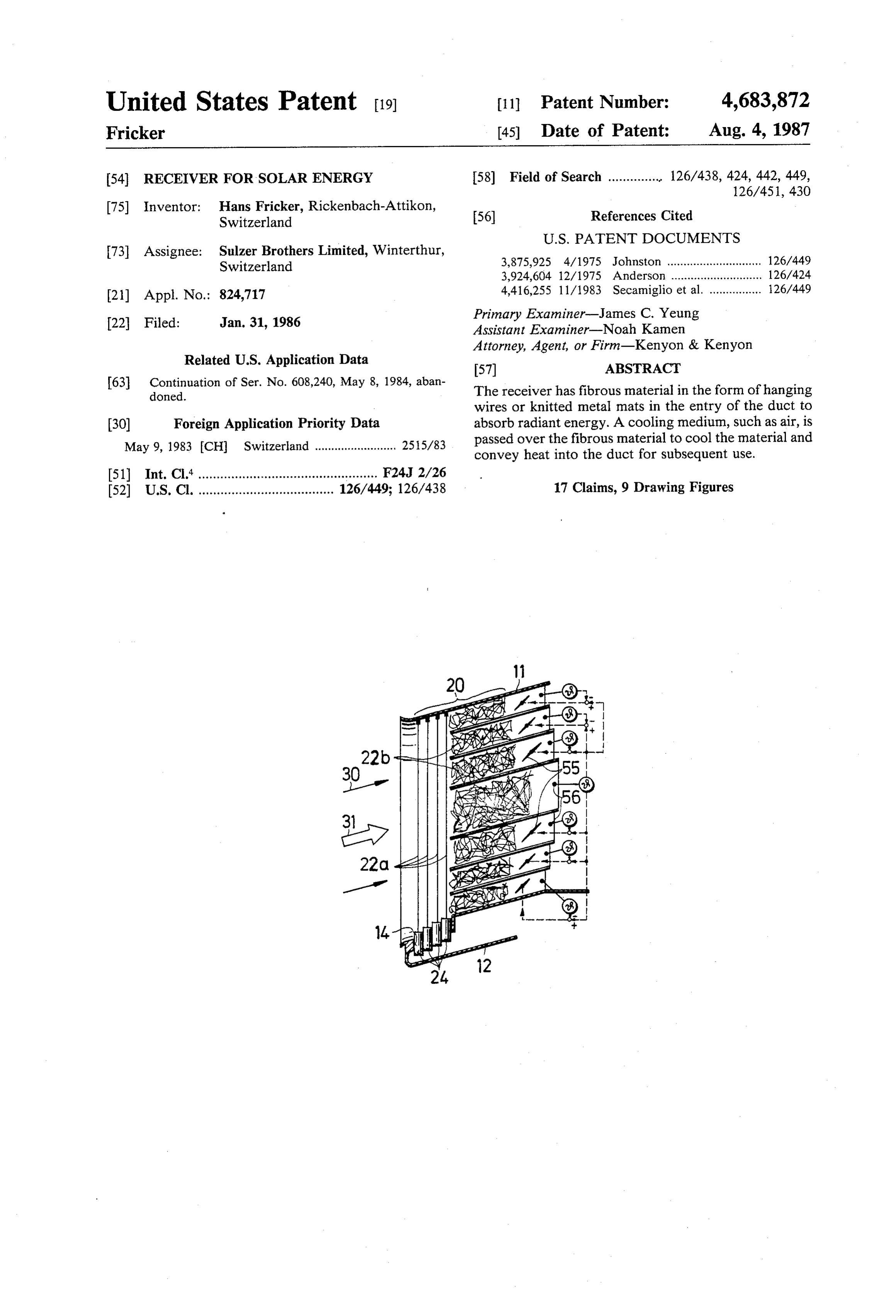
United States Patent (19) 11 Patent Number: 4,683,872 Fricker (45) Date of Patent: Aug. 4, 1987 (54) RECEIVER FOR SOLAR ENERGY 58) Field of Search .............. 126/438, 424, 442, 449,
75) Inventor: Hans Fricker, Rickenbach-Attikon, 56) References Cited Switzerland
73) Assignee: Sulzer Brothers Limited, Winterthur, 3,875,925 4/1975 Johnston ................ ... 126/449 Switzerland
(21) Appl. No.: 824,717 4,416,255 1 1/1983 Secamiglio et al. ................ 26/449 22 Filed: Jan. 31, 1986 Primary Examiner-James C. Yeung Assistant Examiner-Noah Kamen
Attorney, Agent, or Firm-Kenyon & Kenyon
Related U.S. Application Data 57) ABSTRACT 63 Continuation of Ser. No. 608,240, May 8, 1984, aban The receiver has fibrous material in the form of hanging doned.
wires or knitted metal mats in the entry of the duct to (30) Foreign Application Priority Data absorb radiant energy. A cooling medium, such as air, is May 9, 1983 CH Switzerland ......................... 2515/83 passed over the fibrous material to cool the material and convey heat into the duct for subsequent use.
51) Int. Cl." ................................................. F24J 2/26 52 U.S. Cl. ................. ... 126/449; 267438 17 Claims, 9 Drawing Figures
Page 2
Drawing sheet — no readable text.
Page 3
Drawing sheet — no readable text.
Page 4
restricting means within the duct entry for channeling
RECEIVER FOR SOLAR ENERGY the flow of cooling medium therethrough. This permits greater mass flows of the cooling medium in zones of
This is a continuation of application Ser. No. 608,240, relatively high radiation density than in zones of rela filed May 8, 1984, now abandoned. tively low radiation density. Further, the fibrous mate This invention relates to a receiver for solar energy. rial may have a variable density across the duct entry to As is known, various types of receivers have been effect greater mass flows in the zones of relatively high known for receiving and converting the energy of con radiation density than in the zones of relatively low centrated solar radiation. One known construction, for radiation density. Still further, the fibrous material may example, has been disposed on a tower which receives 10 have a finer cross-section in the zones of relatively high solar radiation by way of an array of adjustable mirrors. radiation density than in the zones of relatively low In this case, the receiver has been provided with a heat radiation density. These various features ensure that the exchange surface in the form of a plurality of tubes final temperature at the exit from the duct is very uni through which a heat-receiving medium is conveyed. form over the cross-section of the duct.
Such a receiver provides for a high rate of heat transfer 15 In order to further even out the final temperature of and, thus, the walls of the tubes experience a high tem the air flowing from the duct, a plurality of walls may perature difference. However, considerations of extend within the duct entry in order to subdivide the strength and of heat stressing of the tube walls make it entry into a plurality of parallel flow paths for the cool impossible to heat the tube material to very high tem ing medium. In addition, adjustable flow restricting peratures. As a result, the heat-receiving medium which 20 means may be disposed in these flow paths about the also acts as a coolant for the tube walls cannot be heated periphery of the duct. Still further, temperature detec to very high temperatures either. Accordingly, receiv tors may be disposed downstream of the fibrous mate ers of this type of construction have been relatively rial in the flow paths for sensing the temperature of the low-efficiency converters of solar energy.
Accordingly, it is an object of the invention to pro 25 acooling medium with each detector being connected to vide a receiver for converting the energy of concen ing means inrestricting respective dependence means for adjusting the restrict upon a deviation of a sensed trated solar radiation which can operate at relatively temperature from a set value.
high temperatures.
It is another object of the invention to provide a solar oneWhere of the use is made of the restricting means, at least restricting means is disposed and maintained radiation receiver of relatively high efficiency. 30
It is another object of the invention to transfer a pressure drop toposition.
in a fully open
This permits a very reduced obtained through the fibrous struc relatively large amount of heat to a cooling medium ture.
passing through a solar radiation receiver. In another embodiment, the duct may be shaped to Briefly, the invention provides a receiver for solar direct cooling medium flows from a peripheral Zone energy which is comprised of a duct having an entry for 35 inwardly towards a central zone of the duct to even out receiving radiant solar energy, fibrous absorber material temperature variations in the cooling medium flowing which defines a loose structure within the duct entry in out of the duct.
order to absorb radiant energy and means connected to The various structures for evening out temperature the duct for conveying a cooling medium, such as air, through the loose structure to absorb heat therefrom. 40 have ature the purpose of ensuring that the maximum temper in the fibrous structure is, at most, only slightly in
During operation, solar radiation is absorbed through a considerable depth of the fibrous material used for the excess
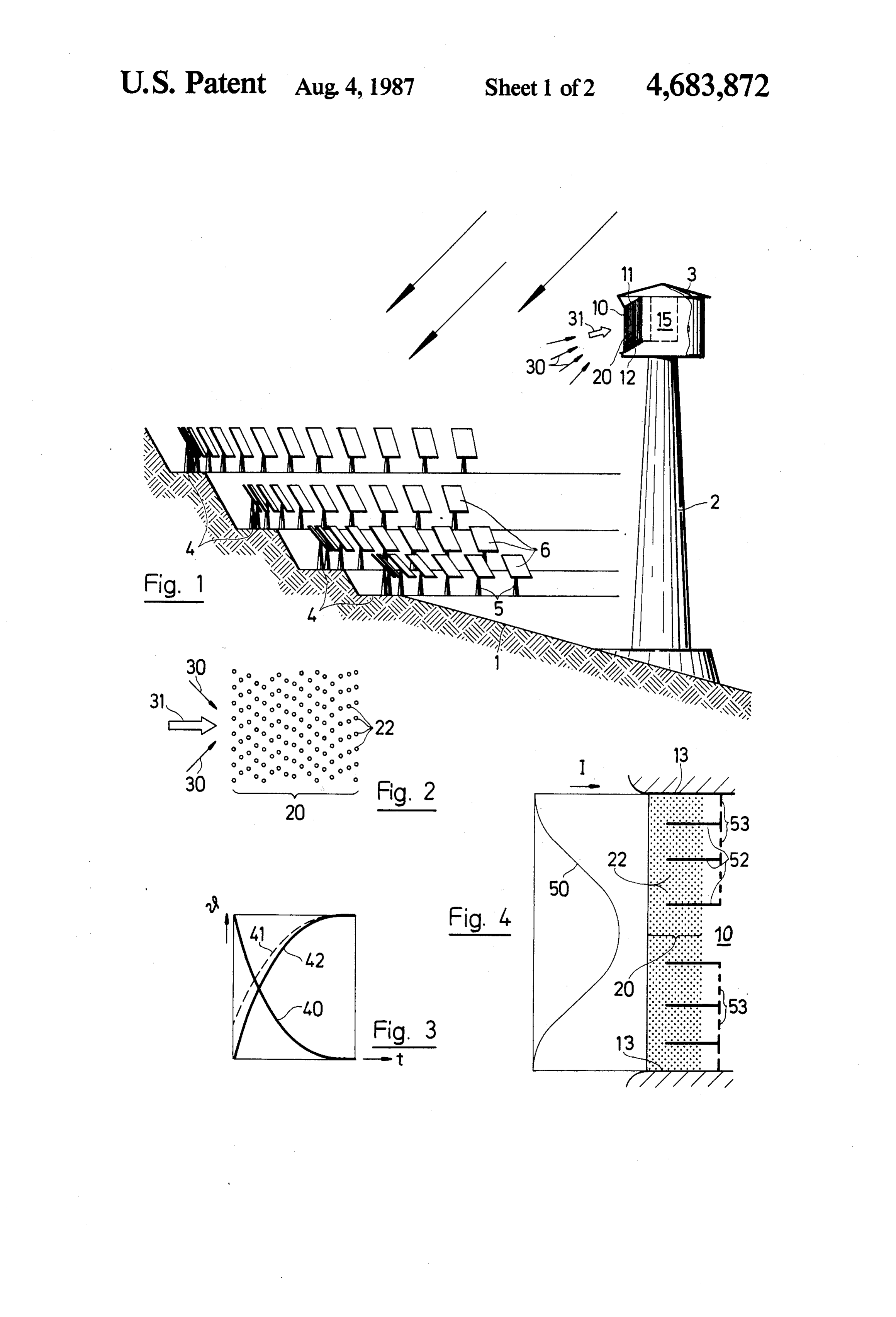
of the average final temperature of the cooling loose structure. Given appropriate air speeds, a consid These and other objects and advantages of the inven erable heat transfer takes place by way of the relatively thin fibers of the loose structure. As a result, the fibers 45 tion will become more apparent from the following can be heated to a temperature relative to the cooling detailed description taken in conjunction with the ac air which is of the order of magnitude of 400K at the companying drawings wherein; FIG. 1 illustrates a perspective view of a solar energy duct entry where the full radiation is incident and which decreases towards zero with increasing structure receiving system employing a receiver in accordance depth, i.e., with increasing air temperature. Conse 50 with the invention;
quently, the maximum temperature of the material of a fibrous FIG. 2 illustrates a horizontal sectional view through the loose structure never rises greatly above the maxi absorber material constructed in accordance mum temperature of the air. with the invention;
One particular advantage of the receiver is that there FIG. 3 graphically illustrates the radiation intensity, is a very reduced mechanical stressing of the material of 55 air temperature and structure temperature plotted the loose structure. Thus, the receiver can readily pro against structure depth;
vide air temperatures of 1,000 degrees C., and more, FIG. 4 illustrates a part cross sectional view of a duct without any great materials problems. entry constructed in accordance with the invention; The fibrous material may be made up of a plurality of FIG. 5 illustrates a modified duct entry in accordance heat resistant wires with the wires vertically disposed so 60 with the invention;
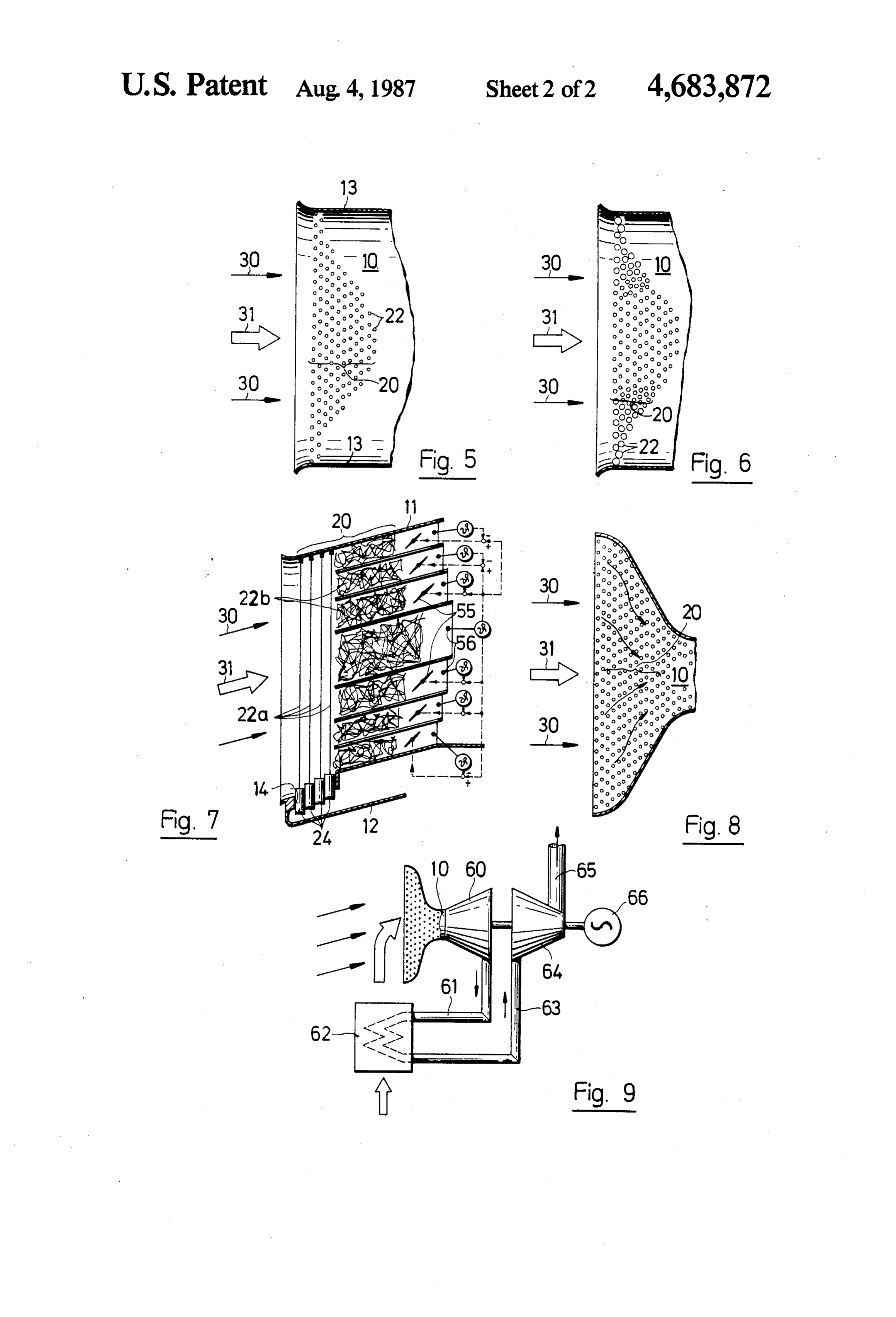
that the cooling medium passes horizontally around the FIG. 6 illustrates a further modified duct entry em wires. This insures that there is very little mechanical ploying different sized wires in accordance with the stressing of the wires. Alternatively, the fibrous mate invention;
rial may be comprised of knitted metal mats. This has FIG. 7 illustrates a vertical sectional view through a the advantage of greatly reducing vibrations and oscil 65 modified duct entry in accordance with the invention; lations of the structure. FIG. 8 illustrates a horizontal sectional view through If the solar radiation inpinges at different intensities a further modified duct entry in accordance with the across the cross-section of the duct, use may be made of invention; and
Page 5
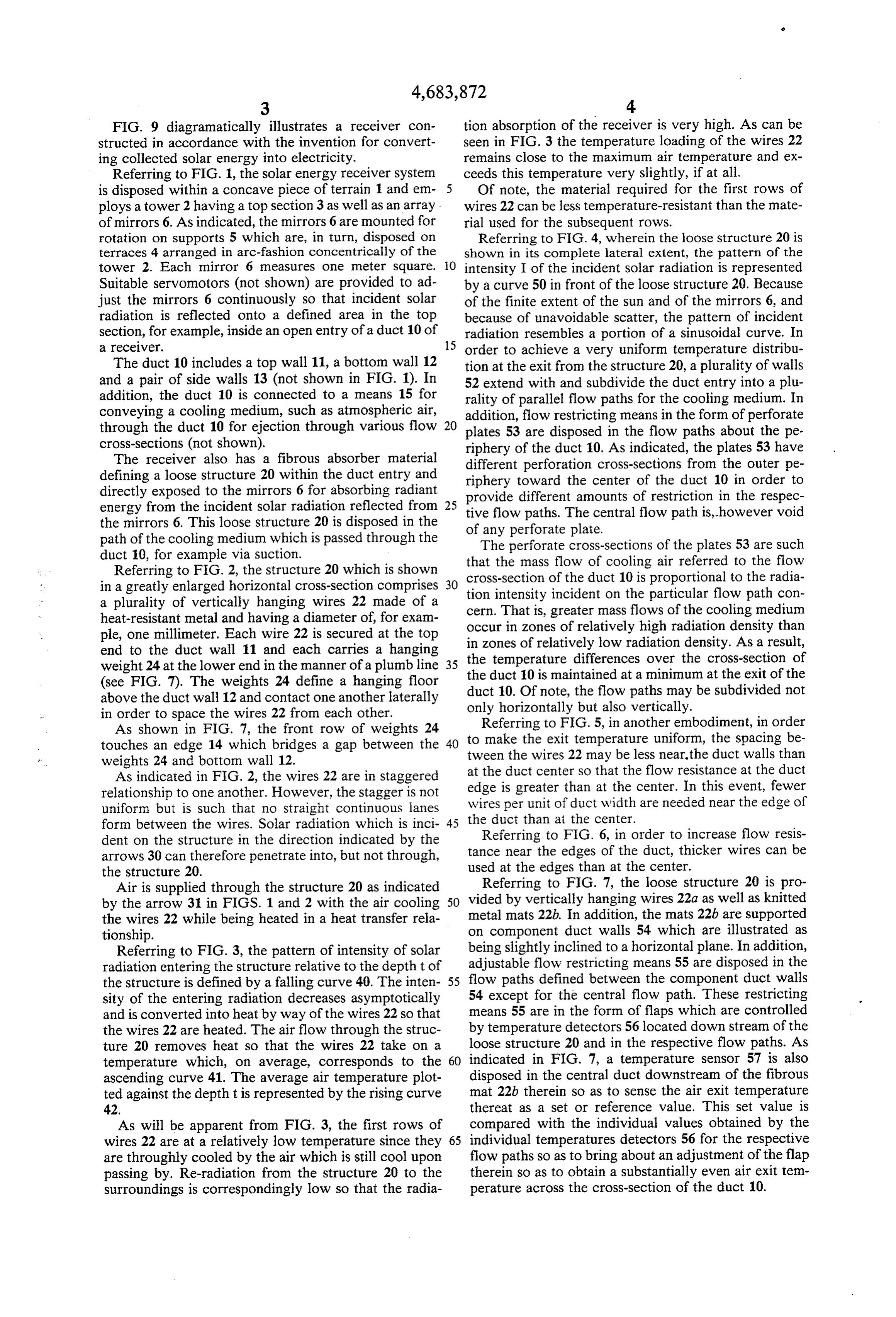
FIG. 9 diagramatically illustrates a receiver con tion absorption of the receiver is very high. As can be structed in accordance with the invention for convert seen in FIG. 3 the temperature loading of the wires 22 ing collected solar energy into electricity. remains close to the maximum air temperature and ex Referring to FIG. 1, the solar energy receiver system ceeds this temperature very slightly, if at all. is disposed within a concave piece of terrain 1 and em Of note, the material required for the first rows of ploys a tower 2 having a top section 3 as well as an array wires 22 can be less temperature-resistant than the mate of mirrors 6. As indicated, the mirrors 6 are mounted for rial used for the subsequent rows. rotation on supports 5 which are, in turn, disposed on Referring to FIG. 4, wherein the loose structure 20 is terraces 4 arranged in arc-fashion concentrically of the shown in its complete lateral extent, the pattern of the tower 2. Each mirror 6 measures one meter square. intensity I of the incident solar radiation is represented
Suitable servomotors (not shown) are provided to ad by a curve 50 in front of the loose structure 20. Because just the mirrors 6 continuously so that incident solar of the finite extent of the sun and of the mirrors 6, and radiation is reflected onto a defined area in the top because of unavoidable scatter, the pattern of incident section, for example, inside an open entry of a duct 10 of radiation resembles a portion of a sinusoidal curve. In a receiver. 15 order to achieve a very uniform temperature distribu The duct 10 includes a top wall 11, a bottom wall 12 tion at the exit from the structure 20, a plurality of walls and a pair of side walls 13 (not shown in FIG. 1). In 52 extend with and subdivide the duct entry into a plu addition, the duct 10 is connected to a means 15 for rality of parallel flow paths for the cooling medium. In conveying a cooling medium, such as atmospheric air, addition, flow restricting means in the form of perforate through the duct 10 for ejection through various flow 20 plates 53 are disposed in the flow paths about the pe cross-sections (not shown). riphery of the duct 10. As indicated, the plates 53 have The receiver also has a fibrous absorber material different perforation cross-sections from the outer pe defining a loose structure 20 within the duct entry and riphery toward the center of the duct 10 in order to directly exposed to the mirrors 6 for absorbing radiant provide different amounts of restriction in the respec energy from the incident solar radiation reflected from 25 the mirrors 6. This loose structure 20 is disposed in the tive of flow paths. The central flow path is, however void any perforate plate.
path of the cooling medium which is passed through the The perforate cross-sections of the plates 53 are such duct 10, for example via suction. that the mass flow of cooling air referred to the flow Referring to FIG. 2, the structure 20 which is shown in a greatly enlarged horizontal cross-section comprises 30 cross-section of the duct 10 is proportional to the radia tion intensity incident on the particular flow path con a plurality of vertically hanging wires 22 made of a cern.
heat-resistant metal and having a diameter of, for exam occurThat in is, greater mass flows of the cooling medium zones of relatively high radiation density than ple, one millimeter. Each wire 22 is secured at the top in zones of relatively low radiation density. As a result, end to the duct wall 11 and each carries a hanging the temperature differences over the cross-section of weight 24 at the lower end in the manner of a plumb line the duct 10 is maintained at a minimum
(see FIG. 7). The weights 24 define a hanging floor duct 10. Of note, the flow paths may beatsubdivided the exit of the not above the duct wall 12 and contact one another laterally only horizontally but also vertically. in order to space the wires 22 from each other. Referring to FIG. 5, in another embodiment, in order As shown in FIG. 7, the front row of weights 24 touches an edge 14 which bridges a gap between the 40 to make the exit temperature uniform, the spacing be tween the wires 22 may be less near.the duct walls than weights 24 and bottom wall 12.
As indicated in FIG. 2, the wires 22 are in staggered at the duct center so that the flow resistance at the duct relationship to one another. However, the stagger is not edge is greater than at the center. In this event, fewer uniform but is such that no straight continuous lanes the wires per unit of duct width are needed near the edge of form between the wires. Solar radiation which is inci duct than at the center.
dent on the structure in the direction indicated by the Referring to FIG. 6, in order to increase flow resis arrows 30 can therefore penetrate into, but not through, tance near the edges of the duct, thicker wires can be the structure 20. used at the edges than at the center. Air is supplied through the structure 20 as indicated Referring to FIG. 7, the loose structure 20 is pro by the arrow 31 in FIGS. 1 and 2 with the air cooling 50 vided by vertically hanging wires 22a as well as knitted the wires 22 while being heated in a heat transfer rela metal mats 22b. In addition, the mats 22b are supported tionship. on component duct walls 54 which are illustrated as Referring to FIG. 3, the pattern of intensity of solar being slightly inclined to a horizontal plane. In addition, radiation entering the structure relative to the depth t of adjustable flow restricting means 55 are disposed in the the structure is defined by a falling curve 40. The inten 55 flow paths defined between the component duct walls sity of the entering radiation decreases asymptotically 54 except for the central flow path. These restricting and is converted into heat by way of the wires 22 so that means 55 are in the form of flaps which are controlled the wires 22 are heated. The air flow through the struc by temperature detectors 56 located down stream of the ture 20 removes heat so that the wires 22 take on a loose structure 20 and in the respective flow paths. As temperature which, on average, corresponds to the 60 indicated in FIG. 7, a temperature sensor 57 is also ascending curve 41. The average air temperature plot disposed in the central duct downstream of the fibrous ted against the depth t is represented by the rising curve mat 22b therein so as to sense the air exit temperature 42. thereat as a set or reference value. This set value is As will be apparent from FIG. 3, the first rows of compared with the individual values obtained by the wires 22 are at a relatively low temperature since they 65 individual temperatures detectors 56 for the respective are throughly cooled by the air which is still cool upon flow paths so as to bring about an adjustment of the flap passing by. Re-radiation from the structure 20 to the therein so as to obtain a substantially even air exit tem surroundings is correspondingly low so that the radia perature across the cross-section of the duct 10.
Page 6
Of note, if a restricting means is provided in the cen 4. A receiver as set forth in claim 1 wherein said rows tral duct, such may be disposed and maintained in a of wires are staggered in non-uniform manner to elimi fully open position. nate straight continuous lanes between said wires for Referring to FIG. 8, the duct 10 may be shaped to passage of solar radiation through said loose structure. direct cooling medium flows from a peripheral zone 5 5. A receiver as set forth in claim 1 wherein said duct inwardly towards a central zone in order to even out includes a pair of vertical side walls and said wires are temperature variations in the cooling medium flowing spaced apart from each other a less amount at said walls through the duct 10. For example, the duct 10 can be than at the center of said duct.
drawn-in in trumpet-fashion near the loose structure 20 6. A receiver as set forth in claim 1 wherein said duct so as to even out temperature variations in the cooling 10 includes a pair of vertical side walls and said wires are medium, conveniently, the lateral and/or depth distri thicker at said side walls than at the center of said duct. bution of the wires or fibers increases in the air flow 7. A receiver as set forth in claim 1 wherein said wires direction. are disposed to form a loose structure of variable den The flow of hot air which is produced in the receiver sity across the width of said duct.
can be used for various process purposes. For example, 15 8. A receiver for solar energy comprising a material in powder form which is to be altered chemi a duct having an open entry for receiving radiant cally by heating can be placed in the air stream and solar energy and a flow of atmospheric air; thereafter separated after heating. In this case, the a plurality of heat resistant metal wires defining a means for conveying the air through the structure 20 loose structure within said duct entry to absorb can take the form of a connecting chimney in which the 20 radiant energy;
hot air is able to rise. The process can then be carried a hanging weight at a lower end of each wire, each out in the chimney or at an upper end of the chimney. said weight being in lateral contact with an adja Advantageously, particles of the substance to be treated cent weight to space said wires to define a hanging can be dropped through the chimney or a fluidized bed floor; and can be formed in the chimney of the particles. 25 means connected to said duct for conveying the flow The energy obtained from the receiver may also be of air as a cooling medium through said loose struc converted into mechanical or electrical energy, for ture to absorb heat therefrom. example as indicated in FIG. 9. To this end, the duct 10 9. A receiver as set forth in claim 8 wherein said wires is connected to a gas turbine 60 which extends into a are vertically disposed with said means passing the vacuum. An outlet of the turbine is, in turn, connected 30 cooling medium horizontally around said wires. via a line 61 to an air cooler 62. The air which is cooled 10. A receiver as set forth in claim 8 wherein said in the cooler 62 and which may be at sub-atmospheric duct entry receives solar radiation in a pattern to form pressure then passes through a line 63 to a compressor zones of relatively high radiation density and zones of 64 which has an outlet connected to a chimney 65. The relatively low radiation density therein and which fur turbine 60 and compressor 64 are disposed on a com 35 ther comprises restriction means within said duct entry mon shaft on which a generator 66 is disposed. The air for channeling the flow of cooling medium there cooler 62 is so placed that at least some of the cooling through whereby greater mass flows of the cooling air (arrow 31) which is heated therein flows to the entry medium occur in said zones of relatively high radiation of the duct 10 as indicated. Further, compressed air can density than in said zones of relatively low radiation be supplied to the entry of the duct 10 rather than to the 40 density.
chimney 65. Further, the waste heat of the compressed 11. A receiver as set forth in claim 8 wherein said air can, if required, be used as process heat. duct entry receives solar radiation in a pattern to form The invention thus provides a receiver for solar en zones of relatively high radiation density and zones of ergy which is able to absorb a relatively large amount of relatively low radiation density therein and wherein radiant energy while at the same time being effectively 45 said wires have a variable density across said duct entry cooled in an efficient manner. The invention further to effect greater mass flows of the cooling medium in provides a receiver which is able to efficiently convert zones of relatively high radiation density than in Zones solar radiation into useful energy in a relatively efficient of relatively low radiation density. ale. 12. A receiver as set forth in claim 8 wherein said What is claimed is: 50 duct entry receives solar radiation in a pattern to form 1. A receiver for solar energy comprising zones or relatively high radiation density and zones of a duct having an entry for receiving radiant solar relatively low radiation density therein and wherein energy; said wires have a finer cross-section in said zones of a plurality of rows of freely suspended vertical hang relatively high radiation density than in said Zones of ing wires disposed in staggered relationship to 55 relatively low radiation density.
define a loose structure within and substantially 13. A receiver as set forth in claim 8 wherein said covering said duct entry to absorb radiant energy, duct is shaped to direct cooling medium flows from a each said row having said wires disposed in spaced peripheral zone inwardly towards a central zone of said apart and structurally non-connected relation; and duct to even out temperature variations in the cooling means connected to said duct for conveying a cooling 60 medium flowing out of said duct.
medium through said loose structure to absorb heat 14. A receiver as set forth in claim 8 which further therefrom. comprises a plurality of walls extending within and 2. A receiver as set forth in claim 1 wherein each wire subdividing said duct entry into a plurality of parallel has a diameter of one millimeter. flow paths for the cooling medium; adjustable flow 3. A receiver as set forth in claim 1 wherein said duct 65 restricting means disposed in said paths about the pe includes a top wall and a bottom wall and each said wire riphery of said duct; and temperature detectors down is secured at a top end to said top wall and is spaced at stream of said wires and in said flow paths for sensing a lower end from said bottom wall. the temperature of the cooling medium respective
Page 7
therein, each detector being connected to a restricting an array of mirrors for reflecting incident solar radia means for adjusting said restricting means in depen tion into said duct;
dence upon a deviation of a sensed temperature from a a plurality of heat resistant metal wires defining a set value. loose structure within said duct entry and directly 15. A receiver as set forth in claim 14 wherein at least exposed to said mirrors to absorb radiant energy; one of said restricting means is disposed and maintained a hanging weight at a lower end of each wire, each in a fully open position. said weight being in lateral contact with an adja 16. A receiver as set forth in claim 8 wherein said cent weight to space said wires to define a hanging wires have a fine cross-section in a central zone of said floor; and duct than in peripheral zones of said duct. 10 means connected to said duct for conveying a cooling 17. A receiver system for solar energy comprising medium through said loose structure to absorb heat a duct having an open entry for receiving radiant therefrom.
solar energy;
Page 8
UNITED STATES PATENT AND TRADEMARK OFFICE
CERTIFICATE OF CORRECTION
PATENT NO.
DATED
INVENTO R(S) :
HANS FRICKER
It is certified that error appears in the above-identified patent and that said Letters Patent is hereby Corrected as shown below:
Column 6 line 51 Or should be -of Column 7, line 9 'fine" should be -finer
Signed and Sealed this
Eighth Day of March, 1988
Attest:
DONALD J. QUIGG
Attesting Officer Commissioner of Patents and Trademarks
Provenance
- Collection
- Cited prior art
- Original PDF
- patentimages.storage.googleapis.com →
- Filed
- 1986-01-31
- Pages
- 8
- Method
- pdftotext (the PDF's own text layer) + pdftoppm 300dpi page scans
- Source
- Google Patents bibliographic record
- Granted
- 1987-08-04
- Inventors
- Hans Fricker; Gebrueder Sulzer AG
- Transcribed from
- patentimages.storage.googleapis.com →