patent · US4793146
Cold storage structure
27 December 1988
Page 1 — bibliographic record
United States Patent (19) 11 Patent Number: 4,793,146 Ryokai (45) Date of Patent: Dec. 27, 1988 (54) COLD STORAGE STRUCTURE 4,466,256 8/1984 MacCracken ......................... 62/260 (75 Inventor: Kimitoshi Ryokai, Tokyo, Japan Primary Examiner-Henry A. Bennet (73) Assignees: Shimizu Construction Co., Ltd.; Attorney, Agent, or Firm-Scully, Soctt, Murphy & Fujikura Ltd., both of Tokyo, Japan Presser (21) Appl. No.: 70,371 57 ABSTRACT (22 Filed: Jul. 7, 1987 A cold storage structure including: a storage chamber for storing articles, the storage chamber including a (30) Foreign Application Priority Data ceiling, a pair of side walls and a bottom wall, at least Jul. 8, 1986 JP Japan ................................ 61-160164 both the side walls and the bottom wall being formed in Jul. 8, 1986 JP Japan ... ... 6-104517 the ground; a heat accumulating layer arranged in the Dec. 17, 1986 JP Japan ................................ 61-194238 ground to surround at least both the side walls and the (51 Int. Cl.".............................................. F25D 23/12 bottom wall, the accumulating layer being adapted for (52) U.S.C. ......................................... 62/260; 165/45 cooling the storage chamber; and a plurality of heat (58) Field of Search ............................ 62/260; 165/45; pipes mounted on the ground to extend in the heat 126/400 accumulating layer to a position below the bottom wall for heat exchanging with the heat accumulating layer to (56) References Cited cool the storage chamber.
4,346,569 8/1982 Yuan ..................................... 62/260 11 Claims, 7 Drawing Sheets
22A7 VVNZS:
Page 2
Drawing sheet — no readable text.
Page 3
Drawing sheet — no readable text.
Page 4
Drawing sheet — no readable text.
Page 5
Drawing sheet — no readable text.
Page 6
Drawing sheet — no readable text.
Page 7
Drawing sheet — no readable text.
Page 8
Drawing sheet — no readable text.
Page 9
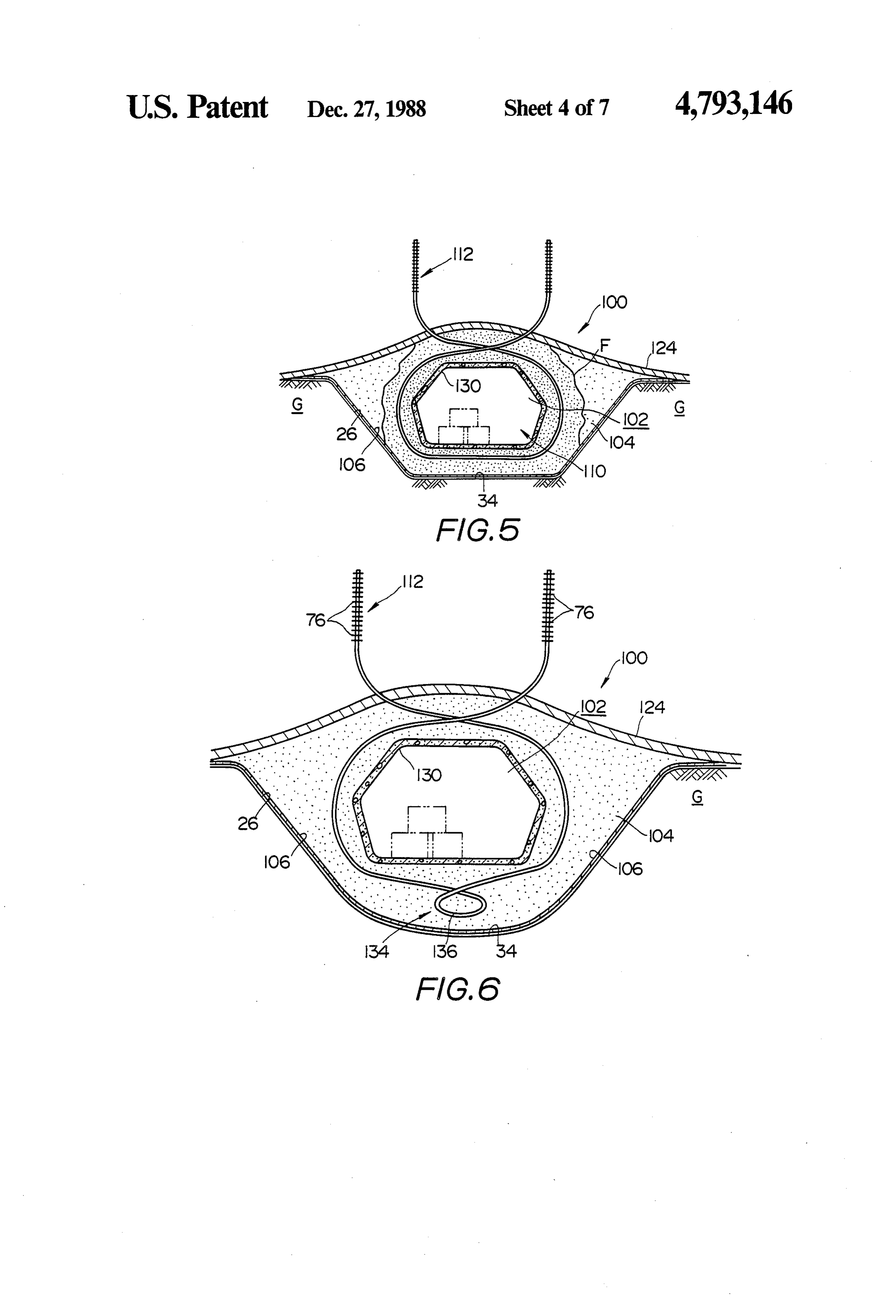
FIG. 6 is a cross-section of a modified form of the
COLD STORAGE STRUCTURE cold storage structure in FIG. 3;
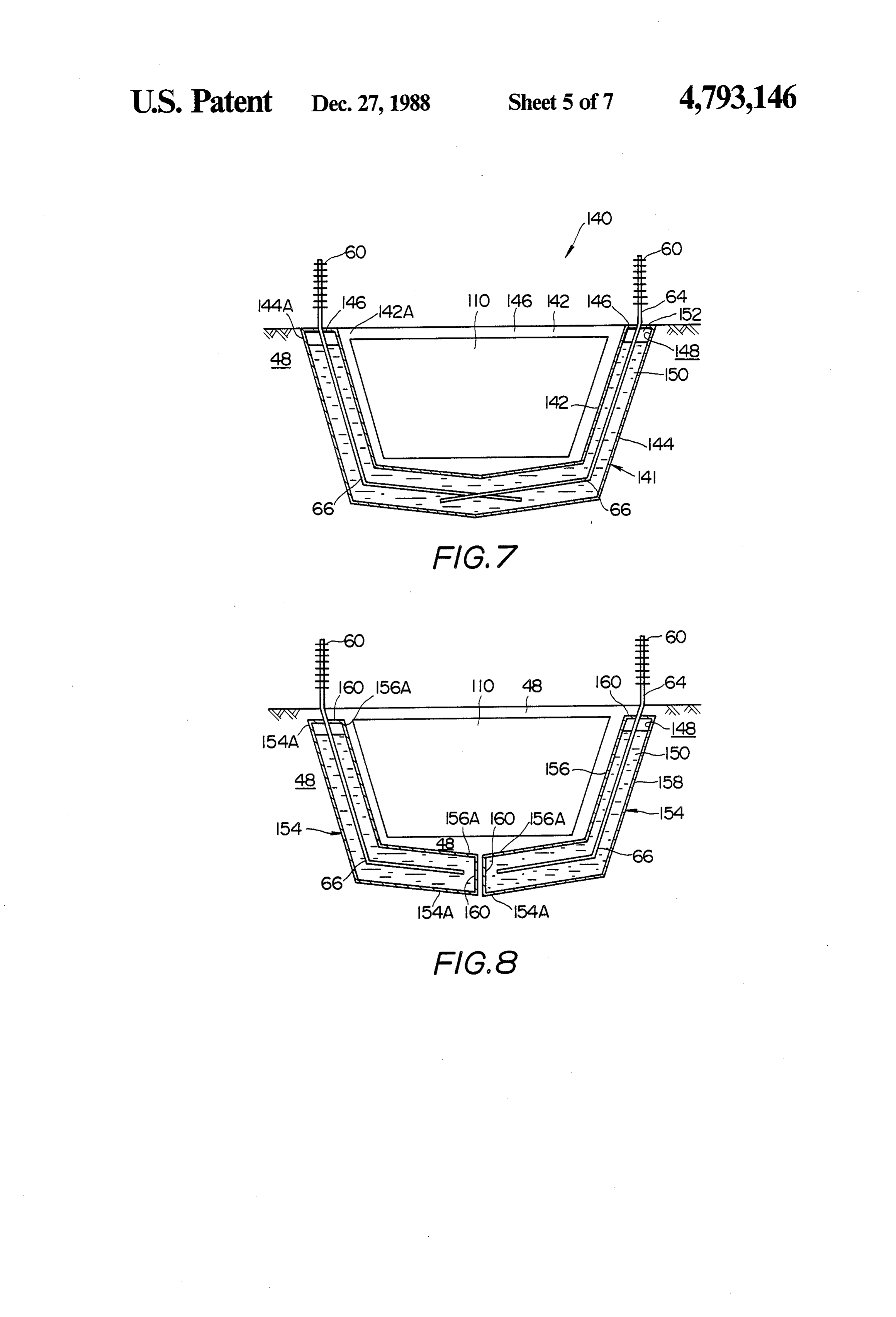
FIG. 7 is a cross-section of another embodiment of
BACKGROUND OF THE INVENTION the present invention;
5 FIG. 8 is a cross-section of a modified form of the
The present invention relates to a cold storage struc cold storage structure in FIG. 7;
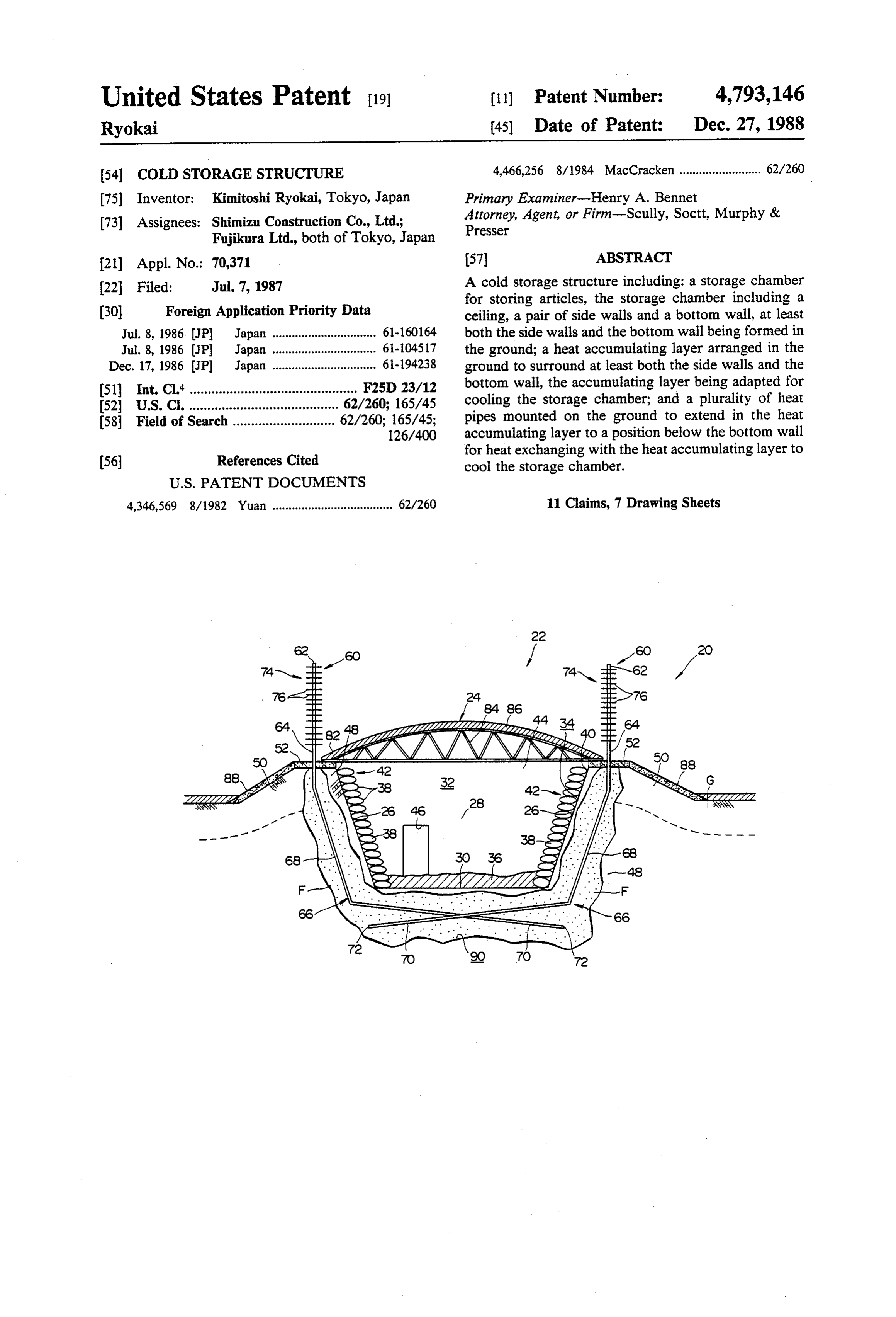
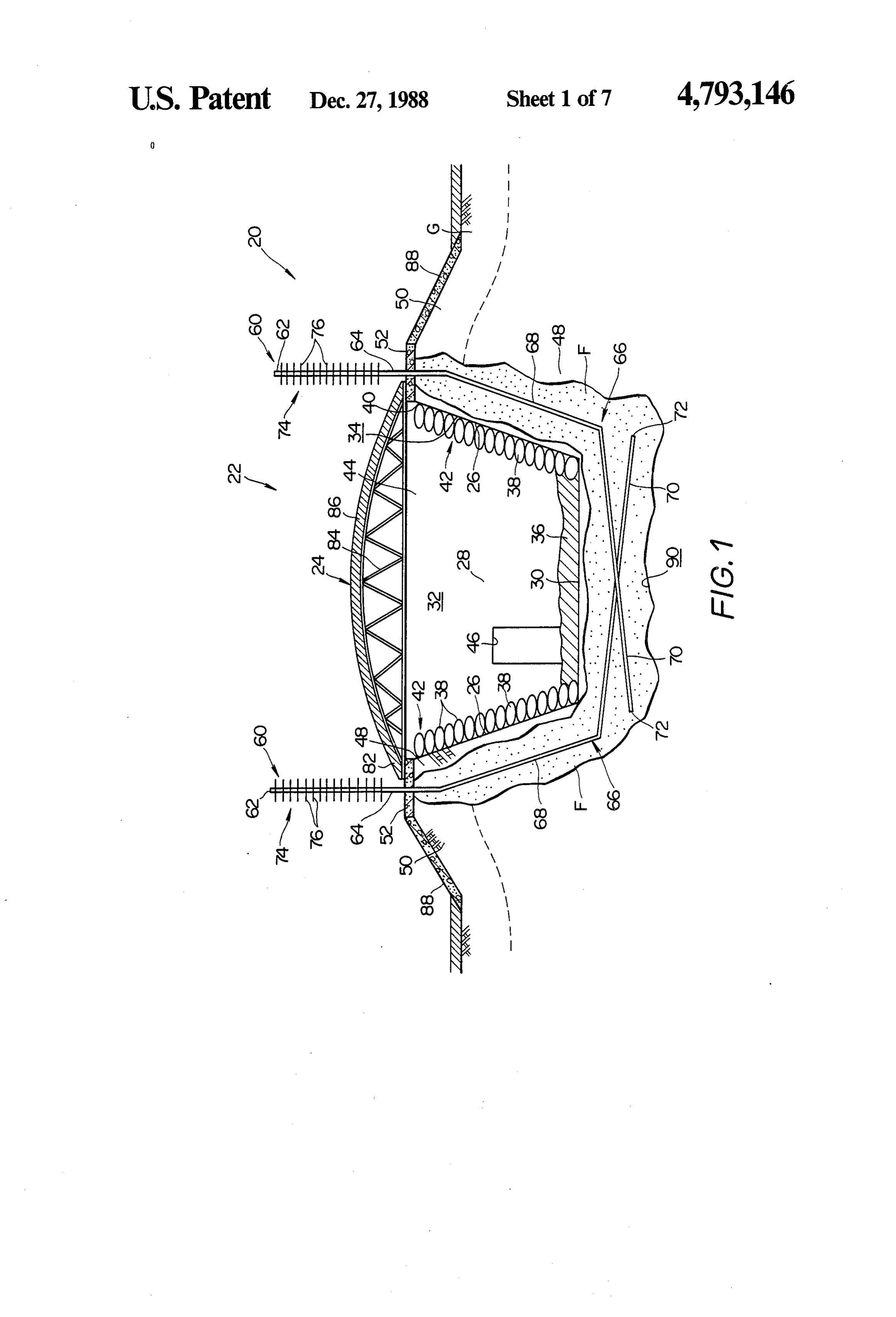
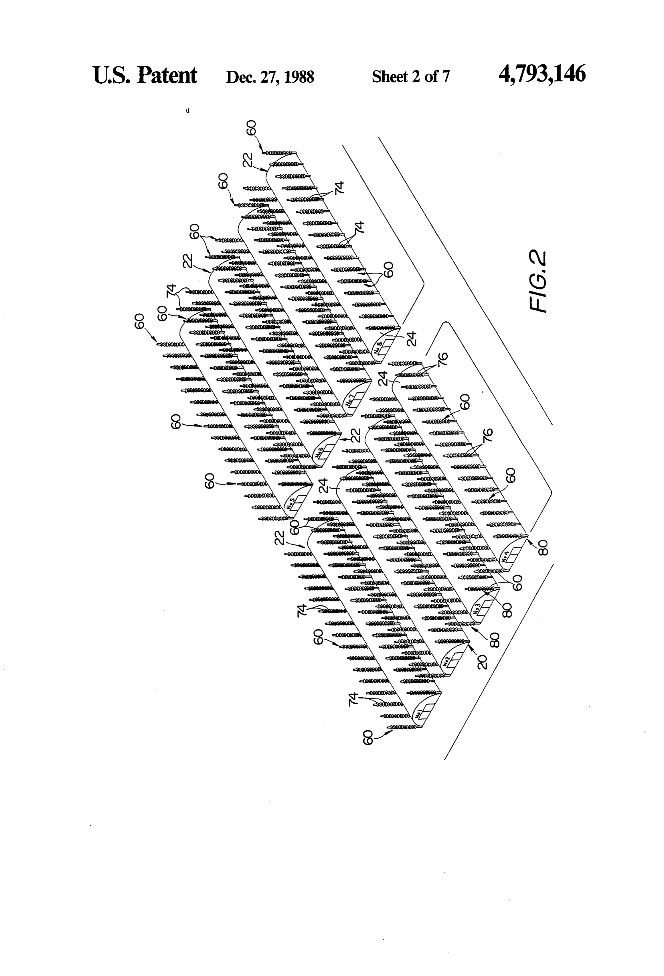
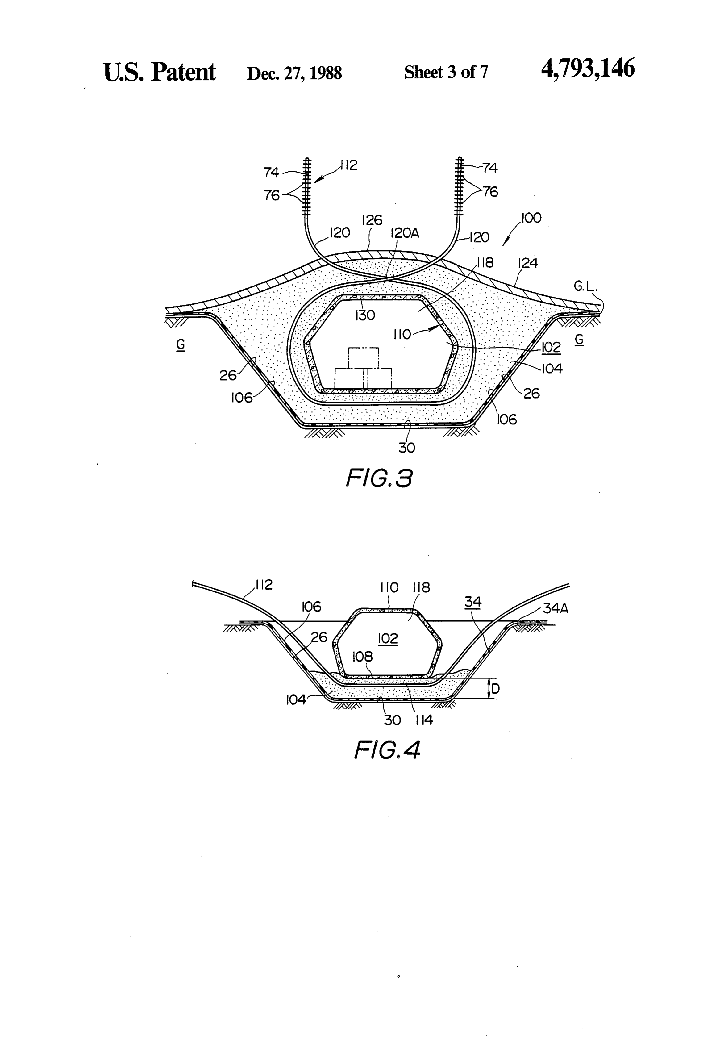
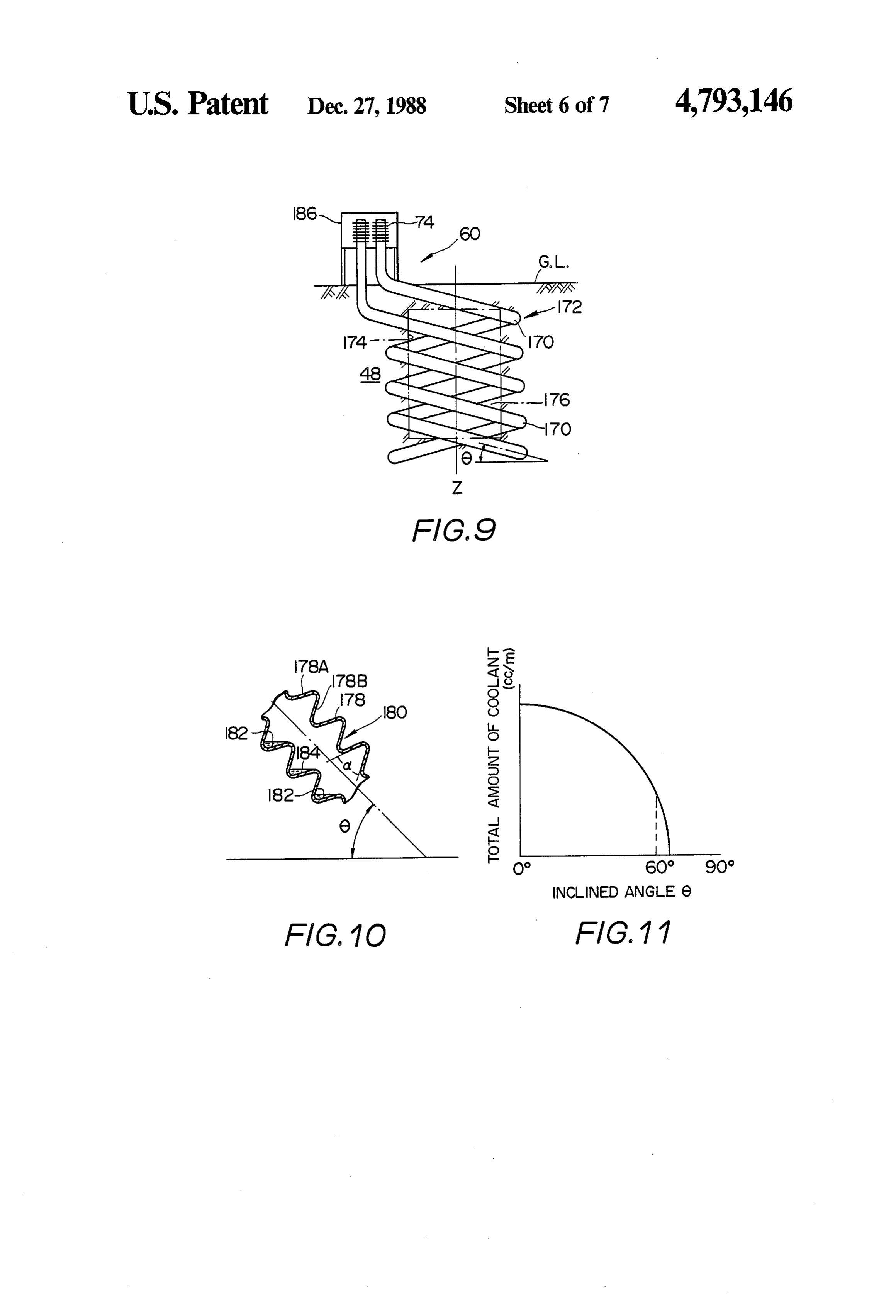
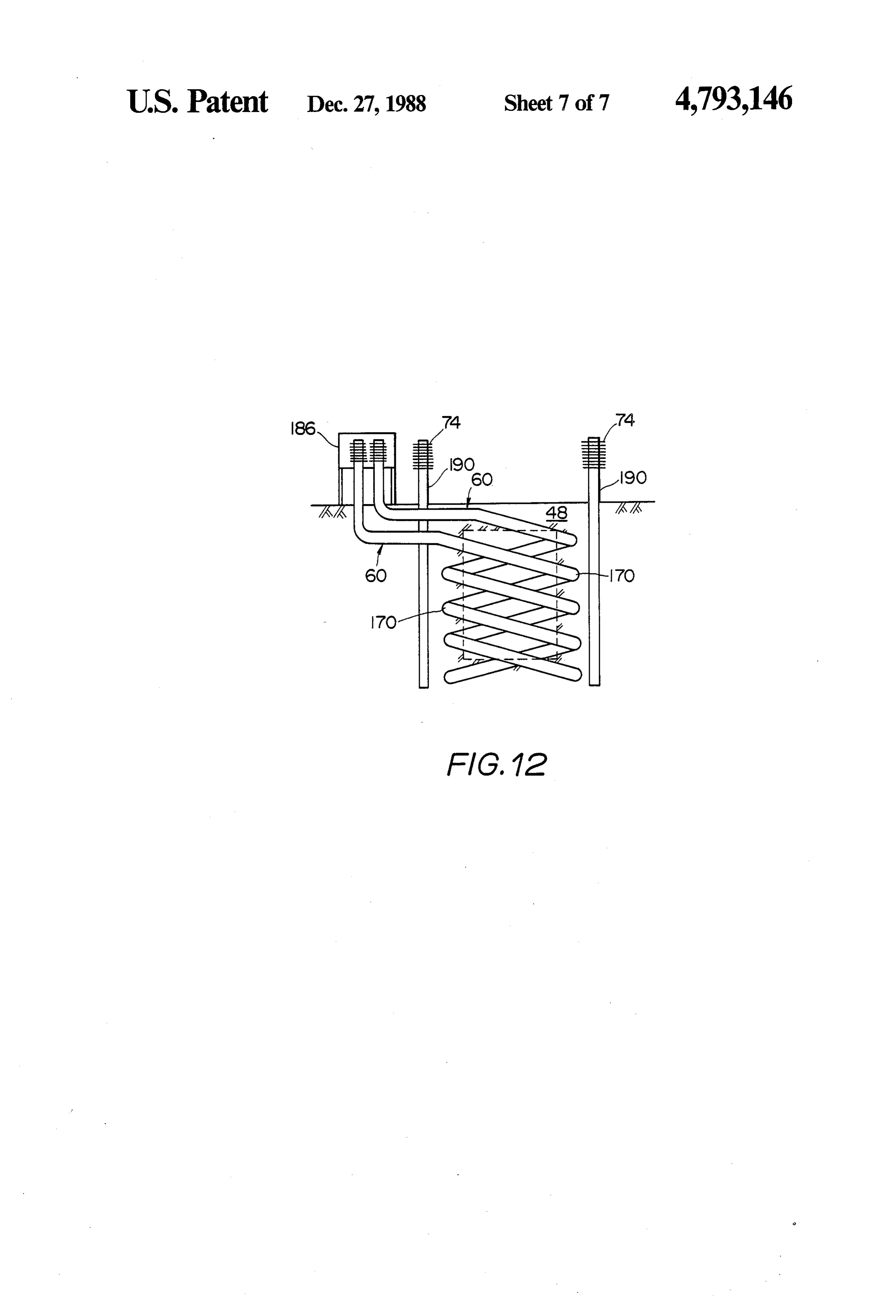
ture including a storage space for storing articles, the FIG. 9 is a vertical section of a modified cold storage storage space being adapted to be cooled with a frozen structure in which the storage chamber is illustrated by material surrounding it. a dot-and-dash line for illustration purpose; It is known that cylindrical heat pipes are vertically O FIG. 10 is an enlarged vertical, axial section of the erected on the ground to surround a cold storage cham corrugated portion of one heat pipe in FIG. 9; ber, formed in the ground, with underground portions FIG. 11 is a graph showing the relationship between thereof for producing frozen soil portions in the ground the total amount of the coolant in the corrugated por around the storage chamber to cool the latter. The heat tion of one heat pipe per unit length and the inclined pipe is a device in which heat is transferred according to 15 angle 0 to the horizontal plane; and phase change of an operating medium, contained in it, FIG. 12 is a vertical section of a modified form of the between the gaseous phase and the liquid phase. The cold storage structure in FIG. 9.
frozen soil is produced with the cold atmosphere in the DETAILED DESCRIPTION OF THE winter. PREFERRED EMBODIMENTS This cold storage structure is disadvantageous in that 20 a condensed working medium which is condensed at Referring now to the drawings wherein like refer the upper portion of the sealed cylindrical casing of ence characters designate corresponding parts through each heat pipe rapidly drops to the bottom of the casing, out views. In FIGS. 1 and 2, each cold storage structure so that evaporation of the condensed medium occurs 20 according to the present invention includes a storage mainly at the bottom portion thereof. Thus, endother 25 chamber 22 having a roof 24, a pair of inclined side mic action of heat pipes is limited to their bottom por walls 26 converging downwards, opposite end walls 28, tions, and hence it is hard to produce a frozen soil layer only one of which is illustrated in FIG.1, and a horizon having a large vertical thickness, which is capable of tal bottom wall 30. These members define a storing uniformly cooling a cold storage chamber having a 30 space 32 for storing articles such as food. relatively large height. For constructing each storage chamber 22, a trench Accordingly, it is an object of the present invention the 34 is excavated in the ground G having a freezable soil, to provide a cold storage structure which is capable of tiontrench 34 having a generally trapezoidal cross-sec with its longer side up. The storage chamber 22 has producing a frozen material having a relatively large a floor 36 formed over the bottom wall 30, the floor 36 thickness around the storage space for uniformly cool 35 being made of a revelling concrete but may be made of ing the latter. crushed stones or like materials. A large number of SUMMARY OF THE INVENTION gabions 38 are stacked from the bottom wall 30 to the opening 40 of the trench 34 to form a gabion layer 42 for
With this and other object in view, the present inven covering tion provides a cold storage structure comprising: stor 40 shown, theeach inclined side wall 26. Although not other end wall is also covered with a similar age means for storing articles, the storage means includ gabion layer. The one end wall is covered with a con ing a ceiling, a pair of side walls and a bottom wall, at crete layer 44 and is provided with a door opening 46 least both the side walls and the bottom wall being which communicates to the outside for transporting formed in the ground; heat accumulating means ar articles, such as food, to and from the outside. The ranged in the ground to surround at least both the side 45 trench 34 is surrounded at its opposite side walls 26 and walls and the bottom wall, the accumulating means 26, the other end wall and the bottom wall 30 with a being adapted for cooling the storage means; and a freezable soil layer 48. The freezable soil layer is prefer plurality of heat pipes mounted on the ground to extend ably a cohesive soil, such as clay, which is higher in in the heat accumulating means to a position below the moisture content than sandy soils. The trench 34 is botton wall for heat exchanging with the heat accumu 50 provided at its opening periphery with a bank 50 in the lating means to cool the storage means. shape of a rectangular loop. The bank 50 is covered at BRIEF DESCRIPTION OF THE DRAWINGS its top with a concrete foundation 52 for supporting a roof 24.
The invention will now be described by way of exam A row of heat pipes 60 are mounted at equal intervals ple with reference to the accompanying drawings in 55 on the ground G along each of the side walls 26 for which: freezing the freezable soil layer 48. Each heat pipe 60 FIG. 1 is an enlarged cross-sectional view of one of has a sealed cylindrical pipe 62 made of copper, stainless cold storage structures, shown in FIG. 2, according to steel, aluminium, etc. Each sealed cylindrical pipe 62 the present invention; contains an operating liquid, such as freon and ammo FIG. 2 is a perspective view of a group of the cold 60 nia, in it. Each of the heat pipes 60 in this embodiment storage structures in columns and rows; is distinct from the conventional heat pipe in that the FIG. 3 is a cross-sectional view of another embodi stem portion 64 thereof is continuous to an underground ment of the present invention; portion 66thereof which includes a downward extend FIG. 4 is a cross-sectional view, in a reduced scale, of ing portion 68 which extends downwards in the freez the cold storage structure, in FIG. 3, under construc 65 able soil layer 48 in parallel with the corresponding tion; inclined side wall 26 to a level below but near the bot FIG. 5 is a cross-sectional view of the completed cold tom wall 30. At this level, the downward extending storage structure in FIG. 4; portion 68 laterally bends to form a laterally extending
Page 10
portion 70 which extends below the bottom wall 30 to a 106 is refilled with water containing soil 104 substan position just below the opposite inclined side wall 26. tially to a half of the distance D between the bottom Each laterally extending portion 70 is inclined down wall 30 thereof and the level at which the bottom 108 of wards to its lower end 72. Opposite heat pipes 60 and 60 a prefabricated water-barrier storage chamber 110 is to in adjacent rows 80 and 80 are spaced at their laterally be placed. Then, each of heat pipes 112 is placed at extending portions 70 and 70 for preventing interfer position with its center portion 114 positioned on the ence but the laterally extending portions 70 and 70 may refilled water containing soil 104, after which the be overlapped to some lateral length. The stem portion trench 34 is further refilled with water containing soil 64 of each heat pipe 60 passes through the concrete 104 to about a third of its depth (FIG. 4). Thereafter, a foundation 52 and its head portion 74 has a plurality of 10 prefabricated storage chamber 110 is placed on the heat receiving and radiating fins 76 for enhancing effi water containing soil 104 as illustrated in FIG. 4. The ciency in heat transportation. water containing soil 104 below the storage chamber The roof 24 of each storage chamber 22 is supported 110 preferably be a soil which exhibits a small frost at its peripheral portion 82 on the concrete foundation heave action when it is frozen. With such a soil, adverse 52 and has a roof structure including a plurality of truss 15 effect to the storage chamber 110 is reduced as small as girders 84 and a heat insulating roof plate 86 covering possible when it is frozen. The storage chamber 110 is the truss girders 84. The roof 24 is not limited to this constructed with a concrete pipe, liner plates or like structure but may have other conventional structures. members for forming the storage space 102 having a The reference numeral 88 designates a heat insulating substantially hexagonal cross-section as shown in FIG. layer covering the bank 50. This heat insulating layer 88 20 3 and prevents water from entering the storage space is provided when temperature in the atmosphere is 102. The rear end 118 of the storage chamber is closed relatively high in summer or other seasons. and the front end (not shown) thereof is communicated For constructing the cold storage chamber 34, a to an opening not shown to the outside. Each of the heat trench 34 is excavated in the ground G. Grooves 90 are pipes 112 is bent around the storage chamber 110 thus formed in the trench traversing the trench 34 for receiv 25 placed in position with its opposite free end portions 120 ing underground portions 66 of heat pipes 60 and after and 120 crossed each other, thus forming overlapped placing each heat pipe 60 in position, it is buried as portions 120A. The trench 34 is further refilled with the illustrated in FIG. 1. Then, gabions 38 are stacked to water containing soil 104 for completely covering both form gabion layers 42 for covering opposite side walls the storage chamber 110 and the overlapped portions 26 and 26 and the other end of the trench 34, after 30 120A of the heat pipes 112. The heat pipes 112 are ar which levelling concrete 36 is placed over the bottom ranged at equal intervals in a row as in FIG. 2 longitudi wall 30 of the trench 34 to form a concrete floor 36. nally of each storage chamber 110 with their opposite After forming a concrete foundation 52, a roof 24 is heads 74 in two rows. A heat insulation layer 124 may constructed on it. be formed to cover the water containing soil 104, thus For using the storage chamber 22 as a cold storage 35 refilled, in a hot season. The top 126 of the cold storage chamber, a frozen soil layer F, covering the opposite structure 100 is somewhat higher than the ground level side walls 26 and 26 and the bottom wall 30, is formed G.L. in view of the cost of forming the trench 34. When in the freezable soil layer 48 in winter; the heads 74 of the trench 34 is formed to a relatively large depth, the the heat pipes 60 are cooled with the cold atmosphere, top of the cold storage structure 100 may be flush with so that the working medium is condensed into liquid, 40 the ground surface G.L.
which is evaporated as it descends along the inner walls In the second embodiment, the roof portion 130 of of the underground portions 66 of the heat pipes 60 by the storage chamber 110 may be surrounded with a gravity. Thus, the ground G near the underground frozen soil F, as illustrated in FIG. 5, which may keep portions 66 of the heat pipes 60 is frozen to form a the storage space 102 at 0° C. or lower with a uniform frozen soil layer F which contains a low amount of heat 45 temperature distribution. This facilitates temperature energy. In hot or warm seasons, the storage space 32 is control of the storage chamber 110. A row of heat pipes kept at a low temperature suitable for storing articles by 112 produce the frozen soil F surrounding the storage heat exchanging with the frozen soil layer F. chamber 110 and hence reduce equipment cost. In place of the storage chamber 22, a corrugated pipe, A modified form of the cold storage structure 110 in box culvert or a similar member having such a large SO FIG. 3 is illustrated in FIG. 6 in which the lowermost diameter to provide a sufficient storage space, may be portion 134 of each heat pipe 112 is looped to form a used, in which case such members are embedded or sump 136 of the condensed working liquid. These buried in the ground G. sumps 136 fairly prevent deterioration in cooling capac FIGS. 3 to 5 illustrate another embodiment of the ity of the heat pipes 112 due to the condensed working present invention, which cold storage structure 100 is 55 medium.
generally distinct from the cold storage structure 20 in Still another embodiment is illustrated in FIG. 7 in FIG. 1 in that the storage space 102 is surrounded with which the storage chamber 110 is received in a bowl a water containing soil 104 with a high water retentiv shaped coolant reservoir 141 which is buried in the ity. The water containing soil 104 may contain a water ground G. The coolant reservoir 141 has a double wall into which is dissolved a substance, which provides a structure including an inner bowl-shaped wall 142, an high freezing-point depression, such as sodium chloride. outer bowl-shaped wall 144 receiving the inner wall For constructing the cold storage structure 100, a wa 142, and an annular edge portion 146 connecting the ter-barrier sheet 106, such as made of a conventional upper peripheral edges 142A and 144A of the inner and synthetic resin, is placed over the front and rear end outer walls 142 and 144 together to form a coolant walls (not shown), opposite side walls 26 and 26 and a 65 receiving space 148. For reinforcing the coolant reser bottom wall 30 for covering the whole faces thereof. voir 141, conventional reinforcing members such as The water-barrier sheet 106 further covers the periph stiffeners are used although not shown. The coolant ery 34A of the trench 34. The trench 34 with the sheet reservoir 141 contains a coolant 150 such as water. The
Page 11
coolant may include an additive, such as NaCl, CaCl, 60 provide fairly larger endothermic area than the heat polyethylene glycol, Na2SO4, etc, for lowering the pipes in preceding embodiments, so that they provide freezing point. Steel-wool, steel-fiber, steel meshes, steel more uniform cooling to the storage chamber 176. Fur reinforcements may be added in the coolant 150 as nu ther, the limitation that the height of the storage cham cleus materials for freezing it. The heat pipes 60 pass at 5 ber depends on the performance of heat pipes 60 is equal intervals through the annular edge portion 146 of improved. In the modified heat pipes 60, it is not neces the coolant reservoir 141 and the underground portions sary to provide any wick since the projected portions 66 extend in it. 178 which serve assumps keep coolant 184 at a substan With such a construction, the cold storage structure tially even amount over their overall length, thus reduc 140 of the third embodiment enhances performance in 10 ing cost.
cooling capacity since heat conductive resistance of the A further modification form of the heat pipes 60 in coolant 150 is relatively small and heat reserving capac FIG. 9 is illustrated in FIG. 12, in which additional ity is enhanced. vertical heat pipes 190 are mounted adjacent to the As an air layer 152 is formed at the upper portion of spiral portion 170 of the heat pipes 60 to form a network the coolant space 148 for preventing damages due to 15 of the heat pipes which freeze the soil 48 more uni expansion of the volume of the coolant 150 when the formly than the heat pipes 60 in FIG. 9. Preferably, the latter is frozen, the inner and outer walls 142 and 144 of heat pipes 190 have the same corrugated structure as the the reservoir 141 may be corrugated plates for this heat pipes 60 in FIG. 10.
purpose. Although it is preferable that accumulated cold tem A conventional heat insulating layer is preferably 20 perature is about 400 C. day or more, used in combina provided between the outer faces of the outer wall 144 tion with the conventional refrigerating machine, the of the coolant reservoir 141 and the soil 48 surrounding cold storage structure according to the present inven the coolant reservoir 141 for enhancing cooling capac tion may be placed into practice in areas where it is ity of the cold storage structure 140. relatively warm in winter.
The coolant reservoir 141 may be in the shape of a 25 What is claimed is:
tube, curved as shown in FIG. 7, of which opposite 1. A cold storage structure comprising: ends are closed. In this case, a large number of such storage means for storing articles, the storage means curved tubes are arranged in a row longitudinally of the including a ceiling, a pair of side walls and a bottom storage chamber 110. wall, at least both the side walls and the bottom The coolant reservoir 141 may be vertically divided 30 wall being formed in the ground; in two halves 154 and 154 as shown in FIG.8. Each of heat accumulating means arranged in the ground to the halves 154 and 154 also has a double wall structure, surround at least both the side walls and the bottom that is, an inner wall 156, an outer wall 158 covering the wall, the accumulating means being adapted for outer face of the inner wall 156, and connecting edge cooling the storage means; and portions 160 for closing the open edges 156A and 158A 35 a plurality of heat pipes mounted on the ground to of the inner and outer walls 156 and 158 to form an extend in the heat accumulating means to a position coolant receiving space 148. Heat pipes 60 extend in below the bottom wall and shaped to surround at corresponding coolant reservoir halves 154. The reser least both side walls and the bottom wall for heat voir halves 154 facilitate fabrication. exchanging with the heat accumulating means to FIG. 9 illustrates a modified form of the heat pipes 60 cool the storage means.
in FIGS. 1 and 7, which modification uses a corrugated 2. A cold storage structure as recited in claim 1, pipe 170 for the underground portion 172 of each heat wherein the storage means comprises recessed walls, pipe 60. A pair of heat pipes 60 surround the circumfer formed in the ground, having an opening above said ential walls 174 of a hollow cylindrical storage chamber walls and a roof supported on the recessed walls for 176 at their underground portions 172 in double helix covering said opening, the recessed walls including the about a vertical center axis Z of the storage chamber side walls and the botton wall; the heat accumulating 176. The inclined angle 0 to the horizontal plane is means includes a freezable soil layer surrounding the preferably limited within a range in which each pro recessed walls and the bottom wall; and each of said jected portion 178 of the corrugated portion 180 of each heat pipes having a bottom portion extending substan of heat pipes 60 serves as a sump 182 as illustrated in 50 tially laterally in the freezable soil layer below the bot FIG. 10. The inclined angle 0 is preferably 5 to 60 tom wall for freezing the soil layer to a position below although it also depends upon angle a which is formed the bottom wall.
by upper and lower walls 178A and 178B of each pro 3. A cold storage structure as recited in claim 2, jected portion 178. This angular range is based on the wherein the cold storage structure is provided in a plu graph, in FIG. 11, illustrating the relationship between 55 rality, and wherein the cold storage structures are ar the total amount of the coolant 184, retained in the ranged in the ground in columns and rows in close projected portions 178 of a unit length of one corru proximity to each other.
gated portion 180, and the inclined angle 6. In this mod 4. A cold storage structure as recited in claim 1, ification, the head portions 74 of the heat pipes 60 are wherein the heat accumulating means is a freezable soil; placed in a shed 186, having good ventilation, for shell 60 the storage means is a storage chamber buried in the tering from rain and snow and for facilitating mainte freezable soil; and the freezable soil is isolated from the nance. The heat pipes 60 are fairly large in strength and ground by a water barrier layer for keeping moisture flexibility at their corrugated portions 180 and are less from escaping said freezable soil. liable to damages due to ground subsidence than the 5. A cold storage structure as recited in claim 4, heat pipes of the preceding embodiments. These modi 65 wherein each of the heat pipes includes opposite end fied heat pipes 60 perform endothermic functions over portions and comprises a pair of head portions formed their whole corrugated portions 180 since the projected at each of said opposite end portions, said heat pipes portions 180 serve as a sump 182. Thus, the heat pipes perimetrically surrounding the side walls and bottom
Page 12
wall of the storage chamber with said head portions angle to the horizontal to allow said operating medium exposed to the atmosphere. to accumulate and be retained in said sumps. 6. A cold storage structure as recited in claim 1, 9. A cold storage structure as recited in claim 8, wherein the heat accumulating means is a reservoir wherein the corrugated portion is constructed to have having a double wall structure for containing a coolant 5 axial flexibility to prevent damage due to ground subsi therein, the reservoir receiving the storage means dence.
therein; and the heat pipes are arranged to extend in the 10. A cold storage structure as recited in claim 5, coolant.
7. A cold storage structure as recited in claim 1, each wherein the storage chamber includes a roof portion; wherein each of the heat pipes includes a spiral portion 10 heat pipe further surrounds the roof portion and laterally surrounding the perimeter of the side walls of has crossed portions crossing each other above the roof said storage means. portion and in the freezable soil. 8. A cold storage structure as recited in claim 7, 11. A cold storage structure as recited in claim 10, wherein each spiral portion includes a corrugated por wherein each heat pipe includes a looped portion lo tion for defining sumps to accumulate an operating 15 cated below the bottom wall.
medium, whereby each spiral portion is inclined at an : :
Provenance
- Collection
- Cited prior art
- Original PDF
- patentimages.storage.googleapis.com →
- Filed
- 1987-07-07
- Pages
- 12
- Method
- pdftotext (the PDF's own text layer) + pdftoppm 300dpi page scans
- Source
- Google Patents bibliographic record
- Granted
- 1988-12-27
- Inventors
- Kimitoshi Ryokai; Fujikura Ltd; Shimizu Construction Co Ltd
- Transcribed from
- patentimages.storage.googleapis.com →