patent · US4346569
Natural ice for cooling energy
31 August 1982
Page 1 — bibliographic record
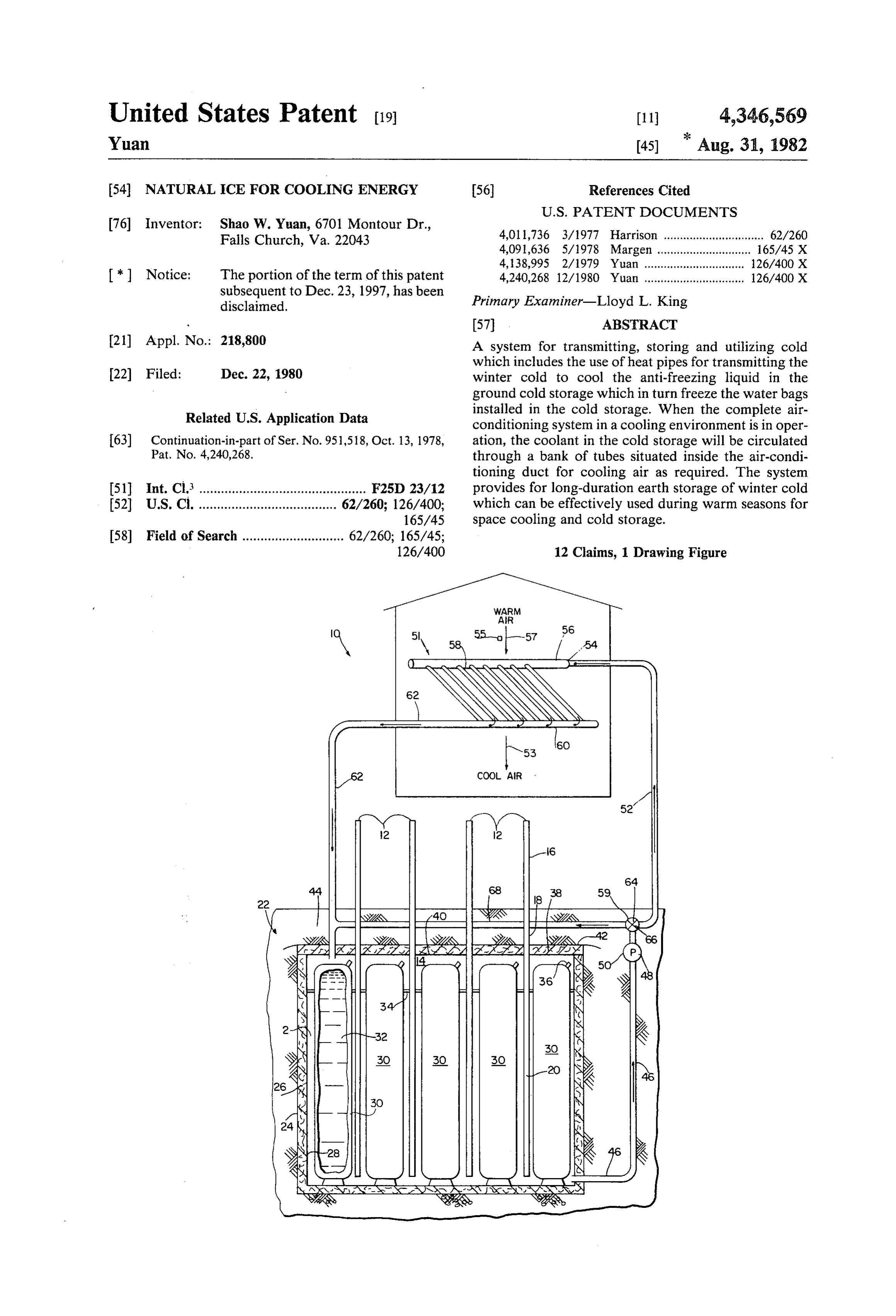
United States Patent (19) 11 4,346,569 Yuan (45) Aug. 31, 1982 54 NATURAL ICE FOR COOLING ENERGY 56) References Cited
76 Inventor: Shao W. Yuan, 6701 Montour Dr., 4,011,736 3/1977 Harrison ............................... 62/260 Falls Church, Va. 22043 4,091,636 5/1978 Margen ....... ... 165/45 X 4,138,995 2/1979 Yuan ............................... 26/400X * Notice: The portion of the term of this patent 4,240,268 12/1980 Yuan ............................... 126/400X subsequent to Dec. 23, 1997, has been Primary Examiner-Lloyd L. King disclaimed.
21 Appl. No.: 218,800 A System for transmitting, storing and utilizing cold which includes the use of heat pipes for transmitting the 22 Filed: Dec. 22, 1980 winter cold to cool the anti-freezing liquid in the ground cold storage which in turn freeze the water bags
Related U.S. Application Data installed in the cold storage. When the complete air conditioning system in a cooling environment is in oper 63) Continuation-in-part of Ser. No. 951,518, Oct. 13, 1978, ation, the coolant in the cold storage will be circulated Pat. No. 4,240,268. through a bank of tubes situated inside the air-condi tioning duct for cooling air as required. The system (51 int. Cl. .............................................. F25D 23/12 provides for long-duration earth storage of winter cold 52 U.S. Cl. ...................................... 62/260; 126/400; which can be effectively used during warm seasons for 165/45 space cooling and cold storage.
58) Field of Search ............................ 62/260; 165/45;
Page 2
Drawing sheet — no readable text.
Page 3
tank below, neither pump nor thermostat control is
NATURAL ICE FOR COOLING ENERGY required for this system. The mechanical simplicity and the effortless maintenance of this system are evident.
This is a continuation-in-part of my pending applica The extraction of cold from the cold reservoir for tion Ser. No. 951,518, filed Oct. 13, 1978 to be issued as space cooling and cold storage is accomplished by U.S. Pat. No. 4,240,268. I hereby incorporate this patent pumping the coolant from the reservoir through a by reference. closed piping loop. When air conditioning is in opera BACKGROUND OF THE INVENTION tion the coolant is pumped from the reservoir through the piping loop to a bank of tubes situated in the ventila 1. Field of the Invention 10 tion air duct system. As the returning warm air from The present invention relates to utilizing winter cold rooms or other environment passes the bank of coolant more particularly to transmitting and storing winter tubes in the ventilation air duct, it loses heat to coolant cold underground for effective uses during summer in the tubes. The coolant then flows back through the SeaSOS. piping loop to the cold reservoir. In the process of 2. Description of the Prior Art 15 coolant recirculation in the cold reservoir, it is cooled Prior art ground cold storage systems are generally by the ice bags and the coolant circulation cycle re accomplished by blowing winter cold ambient air to peats.
pass through the cold reservoir formed by crushed Accordingly, an important object of the invention is stones and rock beds. In other cases, cold liquid medium to provide for long-duration underground storage of is pumped through pipes embedded in stone and rock 20 winter cold which can be used for space cooling and medium in the form of which constitutes a closed heat cold storage when air-conditioning is required, without exchange system. relying on energy from fossil fuel such as conventional The stones and rocks, as a cold storage reservoir, air-conditioning units.
have several shortcomings. First, cold storage capaci Another important object of the invention is to pro ties are limited because of the narrow temperature 25 vide a highly effecient means for transmitting cold from range for cooling. In other words, the difference of the subfreezing atmosphere or environment into the storage temperature in winter and upper-limit useful ground for cold reservoir through the use of heat pipes temperatures in summer is less than thirty degrees Fahr without the aid of energy consumption pumps and ther enheit (30 F. to 60 F). For example, in a volume of mostatic control.
one cubic foot of stone at a temperature difference of 30 A further and important object of the invention is to 30 F., the energy flux is about 1.3X 10³ BTU. Assuming a summer requirement of 25X106 BTU for an average provide storage a plurality of plastic water bags inside the cold reservoir filled with antifreeze liquid; thereby a size home, a volume of cold storage required for cool considerable increase in heat transfer rate between the ing is estimated at 20x10 cubic feet. In contrast to this heat pipe and the antifreeze liquid can be achieved. large volume, if ice is used for cold storage instead of This, in turn, increases the rate of ice forming.
rock, the required storage volume is about 2.5x10³ A still further and important object of the invention is cubic feet.
Another shortcoming of the stone and rocks as cold to provide means to make and store ice in an under storage is the low thermal conductivity. It would re ground ume can reservoir, thereby a considerable reservoir vol be reduced for the same cold storage capacity quire a long length of liquid pipes and considerable pumping power in order to meet the maximum cooling ofAconventional still further stones and rocks type.
object of the invention is to provide a rate required during hot summer days. very quiet air-conditioning system which is free from SUMMARY OF INVENTION compressor noise.
A still further object of the invention is to provide an
This invention relates to a system for transmitting, 45 economical air-conditioning system which is almost storing and utilizing winter cold, and more particularly, free from maintenance to a system in which winter cold can be stored under and utility costs. ground for subsequent cooling utilization during sum become Further objects and advantages of my invention will mers without relying on conventional air-conditioning ing detailed apparent from an understanding of the follow systems. 50 description of preferred embodiment of my invention.
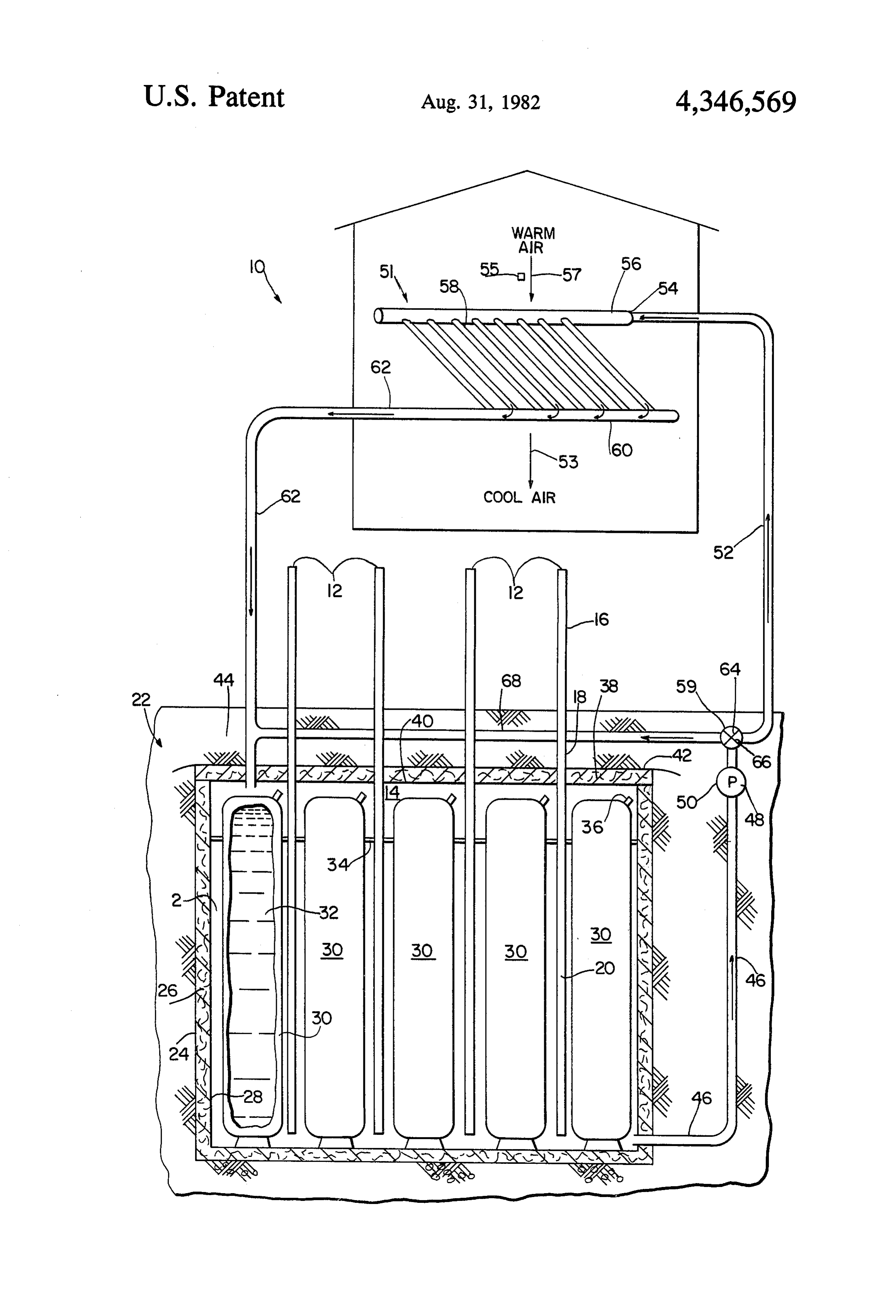
The invention contemplates a novel system for trans mitting, storing and utilizing cold wherein the system DESCRIPTION OF THE FOLLOWING comprises means for transmitting the winter cold above The FIGURE is a diagrammatic sectional view of a ground to freeze bags of water in a reservoir below the system for transmitting, storing and utilizing cold in surface of the ground, and circulation means to circu 55 accordance with the present invention. late the stored cold to the ventilation air duct which cools and dehumidifies the returning warm air flow DESCRIPTION OF THE PREFERRED from the space cooling in an air-conditioning system. EMBODIMENT For accomplishing the foregoing objective, the in Referring to the drawing, the novel transmitting, vention contemplates the use of heat pipes for transmis 60 storing and utilizing system of atmospheric cold, gener sion of the winter cold to an underground coolant (anti ally indicated by number 10, includes a series of heat freezing liquid) tank. The coolant in the tank is cooled pipes 12 for collecting and transmitting cold above the and finally reaches temperatures below 32 F. during ground into an underground liquid coolant tank 14. I the winter season. In turn, the coolant freezes the water define the liquid coolant which remains in liquid state inside the plastic bags which are installed in the coolant 65 under all cold atmospheric conditions that may be trans tank. Since the condenser sections of the heat pipes are mitted by the heat pipe to the said liquid coolant. The above the surface of the ground and the evaporation heat pipe includes a condenser section 16, an adiabatic sections of the heat pipes are situated inside the coolant section 18, and an evaporator section 20 as well as con
Page 4
taining a working fluid (not illustrated). Briefly, cold is picks up the heat from the passing warm air as it flows absorbed by the condenser section 16 which causes the through the manifold 60 and insulated pipe 62 to the vapor therein to condense, and the condensed liquid cold storage tank 14. Then, the cooling process cycle then flows downward through the adiabatic section 18 repeats, to the evaporator section 20 which is located inside the When the air-conditioned environment reaches a liquid coolant tank 14. While the condensed working desired temperature by the cooling system, the pump 50 fluid in the evaporator section 20 of the heat pipe ex will be shut off automatically by an electronic or elec tracts heat from the surrounding liquid coolant 2, it tromechanical thermostatic control 48 which is con changes its phase to vapor which flows upward to the nected to and actuated by a temperature sensor 55 that condenser section 16, and the cold absorption and heat O monitors the temperature of the warm air. As men extraction cycle repeats. tioned previously, the same thermostat control will start At location 22, represented by a pit or excavated the pump 50 when the preset temperature of the air volume of earth where the cold storage tank 14 is em conditioned environment is reached.
bedded. The pit 22 is coated with a layer of foam syn In order to increase the heat transfer rate between the thetic plastics 24 and lined with rigid insulation material 15 liquid coolant 2 in the tank 14 and water 32 in the bags 26 which would hold its shape under hydrostatic pres 30, the liquid coolant is preferably in circulation. This sure. The interior surface 26 of the insulation 28 is lined with a plastic sheet barrier. The shape of the tank 14 can arrangement 59 to the can be accomplished by turning the valve position 66. In this case the liquid coolant 2 is be cylindrical, cubic or any other suitable form which circulated under the encloses plastic bags 30 containing water 32 and is filled lated pipes 46 and 68pressure and back of pump 50 through insu to the cold storage tank with liquid coolant 2. On the other hand, the tank 14 can 14. Since this operation is required only during cold be prefabricated like concentric rigid shells with insulat seasons, the valve setting at position either 66 or 64 can ing material in between. The size and the skin thickness be manually adjusted.
of the water bags 30 are determined by the heat transfer When the temperature above the ground is higher rate between the liquid coolant 2 and water 32. Further 25 than the temperature inside the cold storage tank 14, the more, the plastic material of the water bags 30 must operation of the heat pipes 12 would seem to be re have sufficient strength to withstand the hydrostatic pressure of water 32 and sufficient elasticity to expand versed from that operation as described previously. when water 32 freezes. The bags 30 are held in place by tion However, in this case, the condensed liquid in the sec elastic supporters 34 and have filling tubes 36 in order rise up 30 20 (now functioning as condenser sections) cannot that water can be filled after the installation of the bags. to against gravity, and the heat pipes would cease During the freezing weather, cold is absorbed by the function. There will be no danger on warm days of condenser section 16 of the heat pipe 12 which causes losing the cold from the storage tank 14 to the warmer the vapor therein to condense, and the condensed liquid environment around the sections 16 of the heat pipes. at the sub-freezing temperature then flows downward 35 While a preferred system and a preferred combina to the evaporator section 20. In this continuously auto tion of heat pipes and water bags for use in such a sys matic process of cold absorption and heat extraction, tem have been illustrated and described, it is to be un the liquid coolant 2 in the tank 14 will eventually reach derstood that various changes and arrangement of parts temperatures below 32 F. which, in turn, freezes the may be made without departing from the spirit and water within the bags 30. This constitutes the cooling 40 scope of the invention as defined in the appended and freezing process of the cold storage reservoir with claims.
out any aid of energy operated pump and controls. I claim:
In order to prevent the penetration of summer heat to 1. A system for extracting, transmitting, storing, re the cold storage tank 14, a layer of insulating material 38 covering and utilizing cold, said system comprising: is placed above the cover 40 of the tank 14. It is prefera 45 a. apparatus for extracting cold from the environment; ble that the insulating material 38 is covered by a sheet b. transmitting means comprising a heat pipe for trans of plastic 42 which, in turn, is covered by a thick layer mitting said cold from environment above the ground of soil 44. At the bottom of the tank 14 it is preferable to to a location below the surface of the ground; lay a few layers of gravel or rocks so that water from c. storage means for storing cold including containers of surrounding wet soil, if any, adjacent to the tank 14 can 50 freezable liquid submerged in liquid coolant, said be drained. containers and liquid coolant being located at said When it is desired to use the cold that has been stored location below the surface of the ground for receiv in the tank 14, the thermostatically controled pump 50 ing and storing cold transmitted thereto by said trans will be set in operation. The function of pump 50 is to mitting means;
deliver the liquid coolant in the tank 14 through pipes 55 d. recovery means for recovering cold from said stor 46 and 52 and entrance pipe 54 to the manifold 56 lo age means and delivering it to a second environment; cated inside the ventilation air duct 51. The delivery and pipes 46 and 52 are well insulated by, e.g., conventional e. utilizing means connected to said recovery means for fiberglass pipe insulation tube. The manifold 56 is con receiving cold therefrom and dispersing said cold nected to a bank of tubes 58. 60 throughout said second environment. As the complete air-conditioning system in a cooling 2. A system as defined in claim 1 wherein said storage environment is in operation, the warm air (indicated by means includes a plastic liner for containing said liquid arrow 57) from the returning duct passes through the coolant at said location below the surface of the ground. bank of tubes 58 and gives up the heat to the liquid 3. A system as defined in claim 1 wherein said freez coolant. Hence, the warm air 57 becomes cooler (indi 65 able liquid is water which changes phase to ice upon cated by arrow 53) and will be recirculated throughout being cooled by said liquid coolant.
the house or other environment which is to be cooled. 4. A system as defined in claim 2 wherein said liquid In the meantime, the coolant in the bank of tubes 58 coolant is a substance which is capable of maintaining
Page 5
liquid state upon being cooled by said transmitting cuit pipe means for pumping said liquid coolant through eaS. said second portion to said bank of flow tubes means. 5. A system as defined in claim 2 including insulation 9. A system as defined in claim 6 wherein said bank of means located about said plastic liner for minimizing flow tube means includes a manifold and a plurality of loss of cold to the surrounding earth. flow tubes connected to said manifold; and said recov 6. A system as defined in claim 1 wherein said utiliz ery means including pump means for pumping said ing means includes a bank of flow tube means and means liquid coolant from said location below the ground to for passing relatively warm air across said flow tube for said manifold.
cooling said air. e 10. A system as defined in claim 7 including valve 7. A system as defined in claim 6 wherein said recov 10 means located in said second portion of said closed-cir ery means includes a closed-circuit pipe means having a cuit pipe means for controlling said liquid coolant flow first portion thereof connected to said storage means at through said second portion to said first portion without said location below the ground, a second portion passing through said bank of flow tube means. thereof extending from said location to said bank of 11. A system as defined in claim 1 wherein said con flow tube means for delivering liquid coolant thereto, 15 and a third portion extending from said flow tube back tainer resembles an inflated plastic bag. to said first portion for delivering said liquid coolant 12. A system as defined in claim 1 wherein said con from said flow tube to said first portion. tainer includes at least one filling tube for exchanging of 8. A system as defined in claim 7 including pump substance in said container. sk k sk sk sk means located in said second portion of said closed-cir 20
Provenance
- Collection
- Cited prior art
- Original PDF
- patentimages.storage.googleapis.com →
- Filed
- 1980-12-22
- Pages
- 5
- Method
- pdftotext (the PDF's own text layer) + pdftoppm 300dpi page scans
- Source
- Google Patents bibliographic record
- Granted
- 1982-08-31
- Inventors
- Shao W. Yuan
- Transcribed from
- patentimages.storage.googleapis.com →