patent · US1961358
Electric light and wave apparatus and method for treatment of hydrocarbons
5 June 1934
Page 1
Drawing sheet — no readable text.
Page 2
Drawing sheet — no readable text.
Page 3
Drawing sheet — no readable text.
Page 4
Patented June 5, 1934 1961,358
UNITED STATES PATENT of FICE
ELECTRIC LIGHT AND WAVE APPARATUS
AND METHOD. FOR TREATMENT OF HY
DROCARBONS
Ira Walton Henry, Greenwich, Conn., assignor to Ionizing Corporation of America, New York,
N. Y., a corporation of New York
Application July 30, 1931, Serial No. 554,120
Renewed August 19, 1933
This invention relates to an electric light and of coiled form-in which the field generating cur Wave apparatus and method for treatment of rent passes wholly within the outer skin or sur hydrocarbons, and for other uses. An important face of the tubes or coils which may be called object of this invention is simultaneous dissocia Self-insulating. By so doing, the following im 5 tion and bleaching of the hydrocarbon treated. portant objects and advantages are obtained. 55 By its use even difficultly crackable Pennsyl My new field generating tubes--preferably Vania Crude petroleum oil may be converted read coiled, -although conducting a non-rectified ily into antiknock gasoline, for example. Accord electric current, such as an alternating or pul ing to the American Petroleum Institute data, as Sating current, may be touched by the hands or () is well-known, Pennsylvania crude petroleum tools of Workmen without injury. Copper or 60 while largely used for production of lubricating catalytic metal tubes or coils, on the other hand, oils, is so resistant to efficient cracking, by meth offer electric resistance and have to be carefully ods and apparatus used prior to my ionization insulated, and also constantly cooled to keep the processes of my United States patents and corre electrical resistance and loss of power and also Sponding patents in foreign countries, that to prevent their softening or melting; and any (55 Pennsylvania crude oil has not been used for one gasoline production.
directly or indirectly contacting with them may be shocked, burned, or otherwise injured.
This present invention is, however, an im The hydrocarbon treated, whatever it may be, is provement on that set forth in my pending ap Simultaneously disintegrated or ionized and 20 plication Serial No. 386,182, filed August, 1929, bleached by the electric waves and by the light O for Method and apparatus for treatment of hy rays which effectively dispel impurities and effect drocarbons, and which is efficient for conversion a lighter colored product that is more pure by rea of Pennsylvania crude, and crude petroleum oil son of the bleaching.
from many other fields, into gasoline, as well as My new tubes or coils are transparent. They other petroleum and hydrocarbon oils. are made of . Ordinary lead glass, pyrex glass, This invention is also an improvement on the quartz or the like. When the current is on, they invention set forth in my United States Patent are electric light-ray and electric wave emitting No. 1,709,815, of April 16, 1929, in Fig. 5 of which tubes or coils. They are preferably partially and the description relating to that figure, I vacuumized and in any event have their respec 30 pointed out that a radio audion or vacuum radio tive ends hermetically sealed on end portions of tube might be substituted for the current produc conductors or electrodes with which they form ing and cooling medium conducting coil described the current conveying circuit. The electric oscil in that patent. lations or pulsations within the coils are visible to It is to be noted, however, that such radio vacu the naked eye where the coils are observable, as um tubes or audions are energized by rectified for example at the projecting ends of the coils, as shown in the accompanying drawings. Thus an that is direct cul rents. I have found that such so attendant energized radio receiving tubes are not efficient may visually observe the condition of for conversion of some grades of crude or heavy the oscillations or pulsations in the tubes, the fire molecular Weight petroleum oils into lighter mo quencies of which are regulable by regulation of lecular weight products, such as gasoline and an oscillating or pulsating current with which 90 lubricating oils; and by the present invention, as the circuit is connected.
well as by that of my said pending application, I The current flows or travels along the inner an able efficiently to convert all grades of heavy Surface of the glass in these partially vacuumized petroleum oil known to me into desired lighter tubes probably as a high tension current travels 5 molecular weight oils. on the skin of an ordinary porcelain petticoat The objects of the present invention are in insulator, or, if the tubes are filled with a gas, creased safety in use of my ionization apparatus, through the gas as a conductor. over use of copper on catalytic metal electromag When a high voltage current of from one netice field generating coils, by use of electromag thousand to ten thousand volts is applied to the netic field generating tubes-preferably and best circuit, depending on the length of the coil turns 00
Page 5
from sealed end to sealed end, the OScillating or of condensed gasoline, and which heretofore have pulsating current passes through the Self-insul gone directly into the condensate, seems to ionize ated coil. If the tubes or coils are charged with the mysterious waxy constituent, and also carbon a gas, Such as hydrogen or neon or mercury Vapor in the vapor, and otherwise to convert the con a colored light will be emitted with a character stituents in part and in whole into a non-knock 80 istic electric wave length; in such case the cur ing gasoline even at less than at atmospheric. rent will pass through the gas as a conductor, but pressure and at negligible field temperatures it will still be wholly within the outer surface of temperatures less than that required to Soften the tube or coil. I have found in practice that ordinary lead glass, for example. lo different frequencies in the electromagnetic fields To avoid vapor lockin high-speed internal com 85 are required for the best results, depending On oustion engines the development of which is chair the grades and qualities of the hydrocarbons acterized by increasingly higher Speeds, it has treated; and, for the petroleum crude oils I have been ascertained by scientific tests that gasoline treated, I have varied the Oscillations from about having a gravity of about Baumé 60% is better sixty to about ten thousand or more per second. than gasoline having a gravity of Baumé 70% The electric waves from the osciliations or or higher; and that 72% and higher octane gaso pulsations within the outer surface of the tubes line is slower burning and does not vaporize SO or coills generate a non-Sparking, electromagnetic rapidly as the higher A. P. I. gasoline, in the wave field transversely of the axis of the coil, overheated manifolds of an engine. All really 2 cross-axially in all directions and throughout the anti-knock-knock eliminating,-gasoline has a 95 - length of the coil. gravity of from sixty to fifty per cent Baumé, It is in Such a field that the hydrocarbon start according to the American Petroleum Institute ing material is initially vaporized, being ionized tests and data; by this invention, I obtain gaSO as it appears to me. The vapor is then passed line of the requisite gravity for anti-knock effects, ?25 to a condenser from which a stream of hydro my gasoline product testing also at octane 74%; its carbon liquid flows. Light weight vapors escap and being produced at temperature varying from ing from this liquid and main stream of liquid about 75° to about 400 Fahrenheit, according to is then re-cycled through a Second, similarly gen the character of the oil treated; and the tem erated electromagnetic field and therein and perature being adjusted by regulation of the field 3. thereby liquefied. This two step treatment of generating, non-rectified current used. 5 heavy, petroleum oil, also set forth in my said I have not found it necessary to remove the pending application, results in a Superior quality catalysts from the apparatus now shown, but use of anti-knock gasoline; or of lubricating oil, de of a catalyst is not essential so far as my exper pending on the frequencies established in the ience goes in the use of my new electric light and 35 electromagnetic fields and power applied. wave tubes.
According to the data. Of the American Petro It is to be said that in my use of the glass coils leum institute, average anti-knock gasoline has set forth I have invariably used the high fre an octane test of about seventy-two per cent, but quency alternating électric current circuit Set the best anti-knock gasoline heretofore made forth and claimed in my said pending application, by apparatus other than those embodying ny except that the glass coils have been substituted ills Said invention tested about octane Seventy-four for the catalytic Imetail coills theirein Showin. per cent. These tests are of gasoline made by In the present. application, I show the low ordinary cracking processes treated with chemi pressure apparatus of said application with my cal compounds. Gasoline produced by the pres new glass coils substituted for the metallic Coils, 45 ent invention may be made to respond to these the glass coils being electric wave and light emit- 20 Octane tests by regulation of field oscillations or ting portions of the circuit, and forming a new pulsations; and this invention has for One of its kind of circuit, whether the coils are merely objects and advantages the production of an vacuunized or are charged with a gas effective anti-knock gasoline responding to the octane 5 Seventy-four per cent test and higher; and also of My a colored light and corresponding wave length.
invention may be used with high pressure responding to a Baumé sixty to fifty degree grav apparatus if desired.
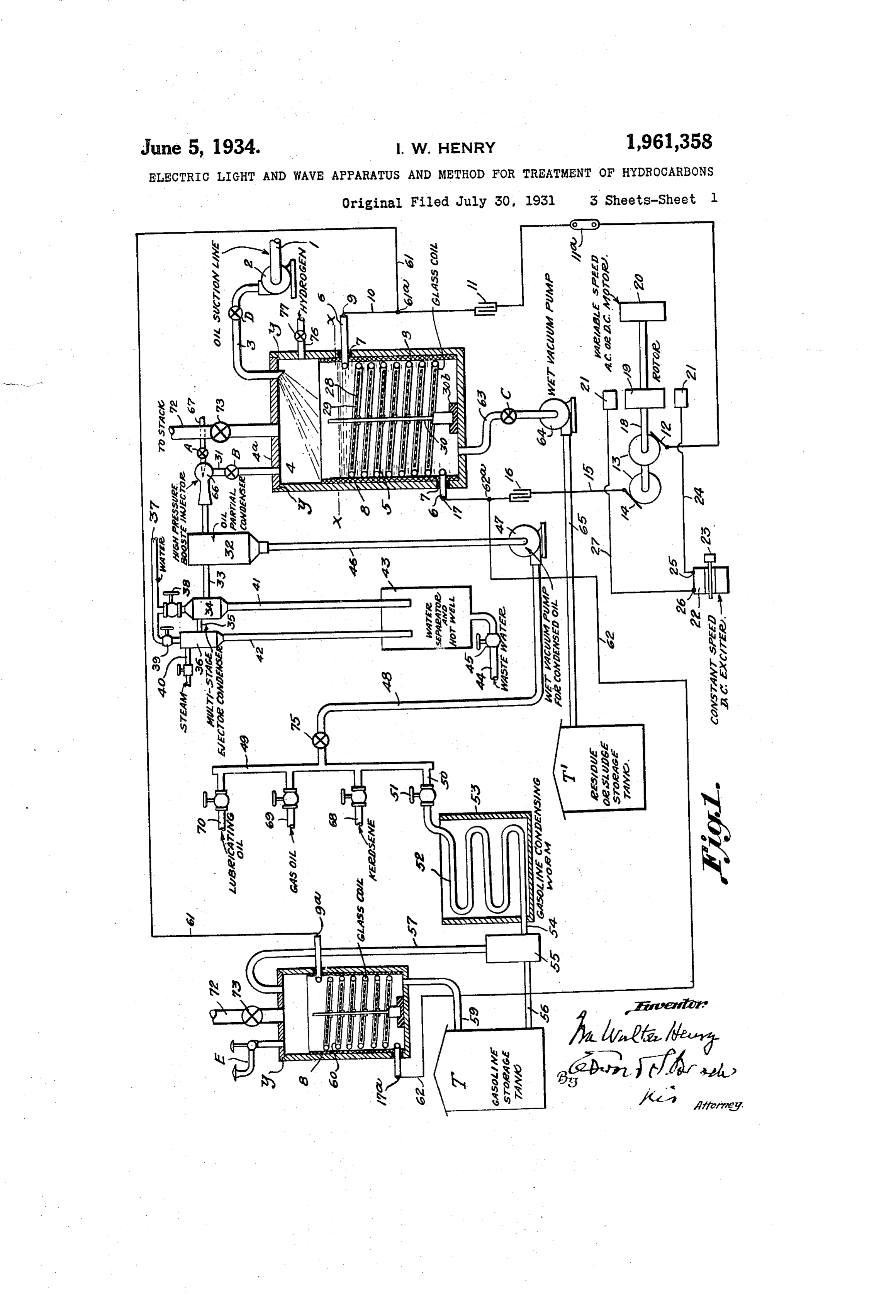
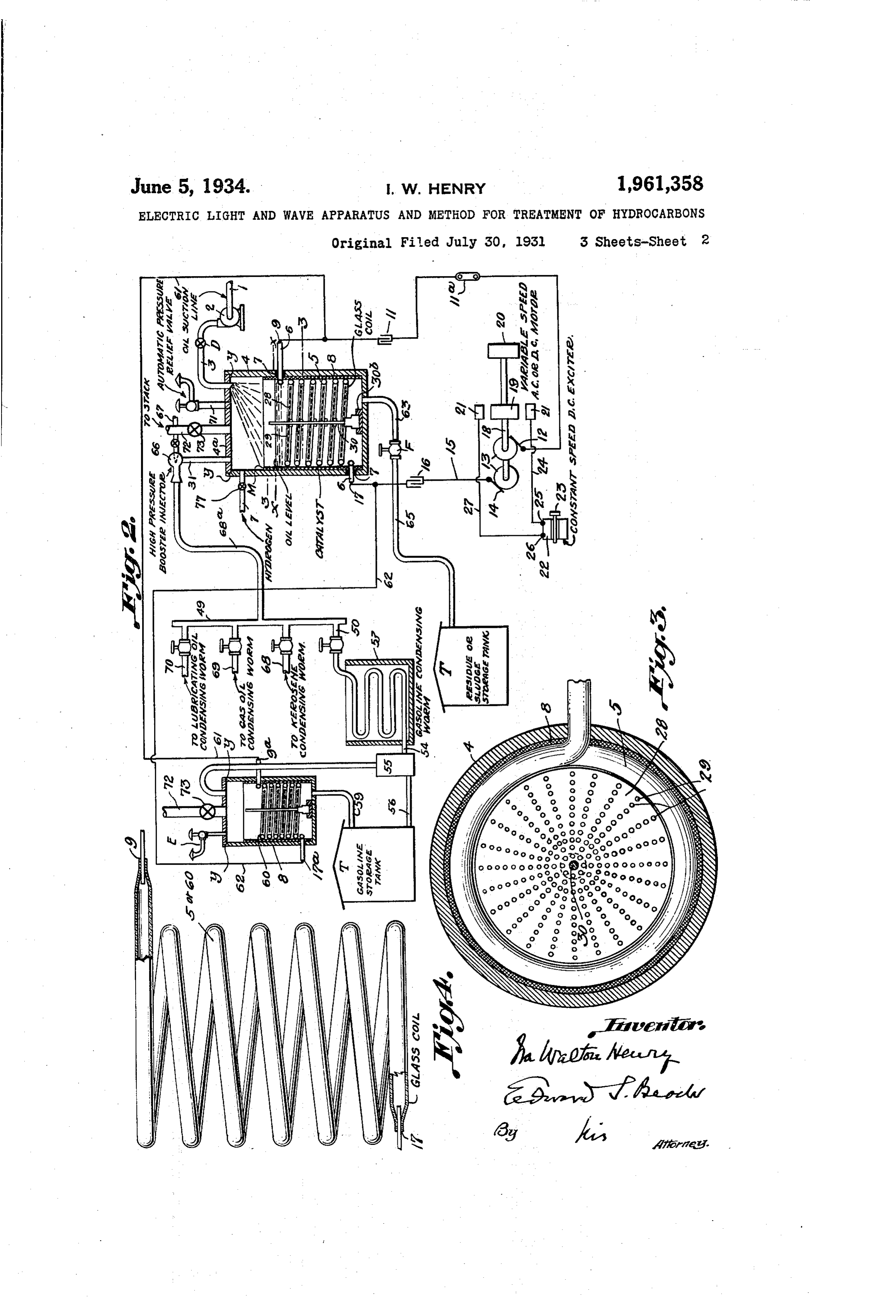
ity test, or better. In the accompanying drawings forming a part According to the American Petroleum Instir thereof and illustrating apparatus embodying the tute data the ideal anti-knock gasoline is charac present invention, r 55 terized by octane.74%; gravity Baumé 60 to 50 degrees. Figure 1 is a view partly in vertical sectional 3. By the present invention obtain Such a elevation and partly in diagram of my new elec product even from Pennsylvania, practically , tric light and electric wave emitting coil appa ratus embodying this invention in a highly vacu semi-crackable, crude oil. The reason for this umized or practically non-pressure apparatus; 35 60 result seems to be that whereas the other crack ing process employs a temperature of about 800 butFig. 2 is a view similar to that shown in Fig. 1, embodying the in Vention in a preSSure ap
Fahrenheit and a high pressure-and such great paratus;
heat and the pressure drive of essential con 'Fig. 3 is a cross-sectional view at line 3-3 of stituents of the crude oil which should be re 65 tained in order to produce an anti-knock gaso- > Fig. 1 and shows removable catalytic members 140 line-I, by my invention, use only low tempera comprising a plurality of transverse catalytic ture and no pressure, and by so doing retain and baffle plates in the electromagnetic field; finally liquefy the constituents that are otherwise Fig. 4 is a view of one of my new electric light... driven Off. . and electric wave emitting coils removed, and 70 For these reasons and others, I prefer the prac showing a conductor end or electrode hermeti tically non-pressure apparatus herein described; cally sealed in each end of the oil, which is of glass but whether the partially vacuumized apparatus or the like.
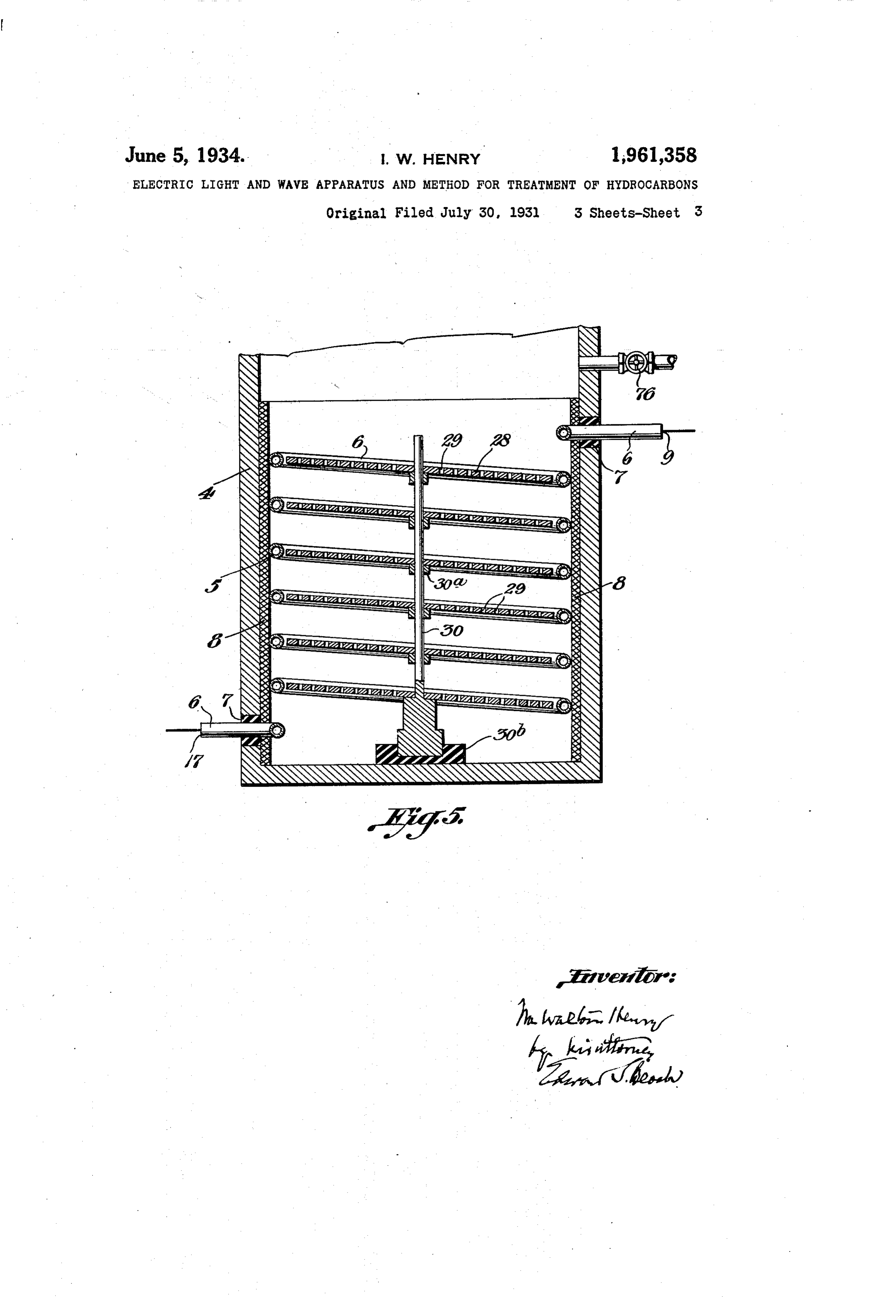
or the pressure apparatus set forth is used, my Fig. 5 is a vertical central section of a vaporizer new step of recovering andliquefying the fugitive, or still showing baffle plates of catalytic metal 5 light weight vapors arising from the main stream inclined in planes of coil turns with dotted lines 50
Page 6
indicating induced dissociating, electric coupling high frequency, oscillating, non-discharging and non-Sparking electro-magnetic field through coil currents through coil turns and baffle plates. 5, and Consequently for treatment of the starting It is noted that the partial vacuum apparatus material in the vaporizing chamber in such a field 80 shown in the drawings is of the barometric type pOSSessing constant frequency of Oscillations ad and capable of producing a partial vacuum of justed to the natural period of the starting mate from about twenty-seven inches to twenty-eight rial under conversion, Inow provide for the alter inches of mercury. nating current circuit, as also set forth in my ap In drawings (Fig. 1), an oil or pre-cracked oil plication Serial No. 386,182, a constant speed, di vapor Supply pipe 1 leads to the intake side of a rect current exciter 22 driven through a power ap 85 0 charging pump 2 which discharges through a pipe plication member 23 with which the exciter is 3 into the upper part of the chamber of a vapor provided. Prior to my invention such an exciter izer 4. If preferred, the starting material of has been mounted on the shaft 18, but I remove it crude oil, raw or pre-cracked gasoline, for ex from the shaft and drive it independently of the ample, may be fed into the vaporizer 4 by gravity, shaft end of the adjustable speed motor 20. This 5 in Some cases, but the use of a feed pump, the permits the exciter 22 to be driven at constant speed of which may be varied from negligible Speed, while the adjustable speed motor 20 may head to high pressure of the starting material fed, have its speed adjusted for varying the frequency is desirable as explained below. of the cycles and of Oscillations in the electromag The lower portion of the chamber of the vapor netic field; this is, adjusted at the will of the op 95 20 izer, 4, which may be called a receiver, or a con eratorto Vary the frequency according to the par tainer, or a still, is provided with an interior, ticular quality or character of the material under tubular, elongated field generating coil 5, of elec treatment. One of the field piece structures 21 for tric light ray and wave emitting material, which extends upwardly from near the vaporizer bottom rotor 19 is in connection through a conductor 24 with the direct current exciter, at 25; and, at 26, O 25 to the line ac-ac which in some cases may be conthe exciter is in electric connection with a con sidered as an oil level; for example, in batch ductor 27 which is in connection with the other treatment of oil. The coil ends 6 extend out field piece structure 21. This special circuit appa wardly through the side wall of the vaporizer. ratus is of substantial economic importance re The end portions of the glass or like coil 5 pass ducing the cost of the electricity otherwise ob 105 30 back through a collar 7 in the vaporizer wall.
The coil is preferably spaced from the vaporizer tained. The practical effect and advantage of the air wall by an asbestos or other suitable cushioning rangement just described, due to the separately packing 8 between the coil and the side wall of and Constantly maintained Speed of the exciter, is 110 theAnconverter. also to maintain electric current strength in all alternating high or low frequency electric the Oscillations of the adjusted electromagnetic
current, depending on the character of the mate field, and consequently to maintain constant fre rial treated, is used to energize the coil for the pro quency of oscillations and constant uniformity of duction, within and transversely of the coil, and treatment of the starting material and of its throughout the length of the coil, of a high or evolved vapor, in saidfield, and constant uniform 15 40 low frequency, oscillating, non-discharging and ity of quality of the vapor of dissociation and re consequently non-sparking electromagnetic field combination, for each particular grade of mate of electric light rays and waves. The energy of rial treated. Uniformity of the vapor results in this field is also exterior to the coil and through unifornity of the quality of the hydrocarbon liq 120 the converter wall as it is also through the mate uid into which the vapor is condensed. 45 rial of the coil, the Supplementary catalytic mem The starting material forms a working load in bers mentioned below, the starting material and the electromagnetic field, and the constant oscil the vapors thereof. The oscillations in this field lations in the field selected for each different kind are of enormous velocity whether they are of a or grade of material are advantageous in treating 25 high, a low or any intermediate frequency. different grades of crude petrofeum and other hy 50 Said field is effective to dissociate hydrocarbo drocarbonaceous starting material, depending naceous starting material into hydrogen and elec upon their carbon content. . . .
trified carbon particles, these products of disso In dissociating different grades or types of ciation having a movement corresponding to that crude petroleum or gas oil or pre-cracked gaso 130 of the field in which they are generated. line, I change the frequency of the oscillations to 55 One end of coil 5 is hermetically sealed at 9, on suit the so-called natural period of the oil or the end of a conductor or electrode 10 provided other starting material. The change in the fre with a condenser 11 and a switch 11. Conductor quency of the oscillations may be. One involving a 10 is in electric connection with the brush 12 of greater or less frequency than that assumed to be 135 one of the two alternating electric current gen a normal frequency.
80 erating rings 13, the other ring 13 being provided In all cases, according to one feature of this in with a brush 14 from which a conductor 15, pro vention based on my discovery of its practical effi vided with a condenser 16, leads into sealed con ciency, the crude petroleum of other hydrocarbo nection at 17 with the other end portion of the coil naceous starting material treated for production 14) 5. This end portioh of conductor 15 forms an of hydrocarbon fluid is first dissociated into a va 65. electrode. The hermetically sealed connections of . por by the action of the electromagnetic field in the coil ends, at 9 and 17, with the conductor ends the vaporizer chamber; the hydrogen and electri are exterior of the condenser. Fig. 5 shows the fied carbon particles of the vapor then recombin sealed coil and conductor ends or electrodes. ing into a purified vapor. Both dissociation and The generator rings 13 are on a shaft 18 carry recombination occur in the electromagnetic field 145 70 ing a rotor 19 and driven by an adjustable speed, and without addition of Oxygen or of hydrogen electric motor 20; the rotor revolving between from any source extraneous to the hydrocarbona field pieces. 21, provided each with a coil not shown, all as usual; but, in accordance with a fea ceous starting material itself. This object, feature and economic advantage tures of this invention, and for effecting a COn of the invention constitute an extremely impor 50 75. stant frequency of adjusted oscillations in the
Page 7
Drawing sheet — no readable text.
Page 8
Condenser and for incorporation thereof as a tion of the catalytic material is a highly impor fluid forming part of the general gasoline Sup tant feature of my invention, as set forth in said ply in the gasoline storage tank T, the discharge application Serial No. 386,182. It is herein shown end portion 54 of the worm 52 leads into the ex the because the effects obtainable are useful with 80 electric light and wave emitting coils when pansion chamber of a gasoline receiver 55 above the material its bottom; the main portion of the gasoline to be treated is of a kind difficult to flowing out of the receiver chamber through an vaporize or liquefy in the said fields. eduction pipe 56 that discharges the main stream The vaporizer 4 has a bottom discharge pipe 63 of gasoline into the gasoline storage tank T. But for carrying off impurities or sludge. It leads 85 to the intake side of a vacuum pump 64 which 10 the exceedingly light, and economically impor discharges through its eduction pipe 65 into a tant fugitive or exceedingly light weight gas, expandingly and continuously rising from the sludge residue tank T.
main stream of the gasoline, flows upwardly forWhen and if the apparatus is to be operated through the receiver 55 and out of it through a put production of lubricating oil, it is desirable to pipe 57 into the chamber of a converter 58 in tion aahead high pressure booster ejector into opera- 90. of the vacuumizing apparatus de which the light weight fugitive fixed gas is con Scribed, if that is used; or ahead of the frac verted into fluid gasoline which flows out through tionating manifold, as the case may be. Such a pipe 59 into a place of reception which is pref a booster ejector is shown and includes a cham erably the gasoline storage tank T. bered member 66 provided at one end with a high 95 20 The converter 58, wherein the vapor escaping pressure steam Supply pipe 67 which delivers from the main gasoline stream is liquefied, is Steam into the chamber of member 66 crosswise provided with a glass or like electric light and wave emitting coil 60, the same as coil 5 in va of the upflow of vapor of recombination from porizer 4; the coil ends projecting through the vaporizer ber 66 is 4 through pipe 31. This ejector mem interposed, conduitWise, in the pipe 31, 00 25 converter walls and being each hermetically the discharge from member 66 being through a sealed on a conductor end, as shown at 9 and 17. portion of the pipe 31. . If the ejector booster This coil 60 is in circuit through leads 61 and member is used, the hydrocarbonaceous vapor as 62 With the conductors 10 and 15. The con cending into the booster member is entrained by 105 verter 58.is shown provided with the removable the high pressure steam.
30 catalytic plates 28, as in the case of the va When and if pressure is desired, the vacuumiz porizer 4.
Apparatus for the purposes described may be ing apparatus and its members may be omitted, made largely of ceramic material when economy and the apparatus constructed as shown in Fig. of plant construction is desired, the coils being 2, in which a conduit 683 connects the booster
35 of glass or the like as above stated. To shut off the booster ejector, a valve A with Substantially better results are obtained for liquefaction of the fixed gas introduced into con which the high pressure steam supply pipe is provided, is closed. The booster ejector structure verter 58, and subjection therein to the action of the oscillating, non-discharging and non-Sparking then becomes merely a portion of the conduit 5 electromagnetic field, by winding the coil 5 clock connection of vaporizer 4 with the partial vacu wise and the coil 60 anti-clockwise as shown, as um apparatus designated by the reference nu described and claimed in my said application, nerals 32 to 48, inclusive. The sludge discharge pipe 63 is provided with
Serial No. 386,182 and as herein also shown.
The alternating current generator driven at aF shut-off valve C in Fig. 1 and a shut-off valve in Fig. 2; and feed pump eduction pipe 3 is 120 45 at a variable speed and in circuit, as described, provided with a shut-off valve D in each figure. with the constant speed direction current exciter When the valve C is closed, the feed pump may produces a constant magnetic field in the gen be operated slowly to Supply vaporizer 4 with a erator when the generator speed is varied. The batch of starting variations in the speed of the generator Create valve D being thenmaterial up to the level ac-ac, closed. Various other valves 125 50 variations in the frequencies without changing either the strength of the alternating field or the may be supplied for convenience in adapting the voltage of the exciter; and the catalytic metal apparatus to various Working conditions. The fractionating manifold 49 is provided as pole-forming portions, if they are used, are al usual with valve take-off pipes such as 68 for ternately polarized, thus alternately subjecting kerosene; 69 for gas oil and 70 for lubricating 130 55 the starting material to polarizing effects. The oil. In the pressure apparatus of Fig. 2 vaporizer , opposite side of each plate serves as a pole.
I have found in practice that the winding of Vaporizer 4 valve
is provided With a fue 72 pro the coils in reverse directions has a new effect vided with a shut-off valve 73. The flue is used on the catalytic electrically energized members only when the converter is to be cleaned out by 135 60 that is quite different from the effect obtained when the coils are both wound in the same di raising the temperature of said field and burn ing sludge and other impurities off interior Sur rection. The coils wound in reverse directions as faces of and within the converter chamber. shown are connected in series and are wound Reduction clockwise and anti-clockwise in order to vary reduction of ofthecurrent strength in the coils by speed of the alternating cur- 40 the magnetic fields produced in the catalytic
metal members, severally, and analogously to the rent generator constitutes the practical Way of field variations obtained by winding electromag obtaining a low temperature of the converter nets in direct current work for production of structure in whole and in part. I have found it north and south poles; the so oppositely wound ience but also fornot very desirable only for safety and conven increased quantitative and qual- 145 70 coils effecting the opposite polarities, act and re act on the catalysts and on the carbon con itative results in the distillation of Some grades tent of the starting material under treatment, I of crude petroleum, to operate at Substantially find that this action and reaction positively in low temperatures; for example, at from about 75 à tensifies the conjoint action of the catalysts and degrees Fahrenheit up to about 250 degrees Fah renheit. Production of motor fuels and the like 50 75 energized carbon particles and that the polariza
Page 9
Drawing sheet — no readable text.
Page 10
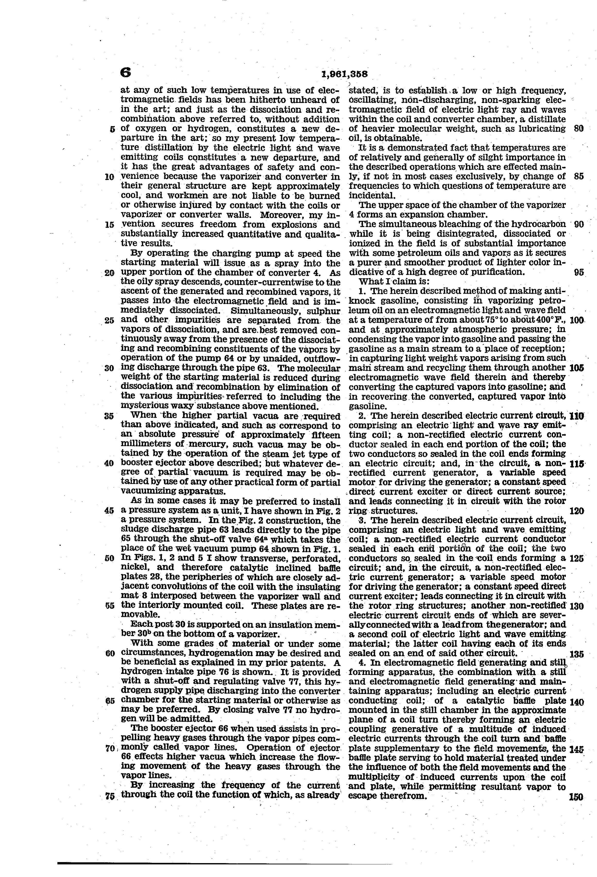
spaced apart, catalytic baffle plates each in the 5. In the apparatus set forth in claim 4, the approximate plane of a coil turn; whereby the coil being made of translucent material emitting electromagnetic field energy is augmented by a electric light bleaching and ionizing rays. multiplicity of induced, dissociating currents 6. In electromagnetic field generating and still through the coil turns and baffle plates, and 80 forming apparatus, the combination with a whereby the material ionized or dissociated in chambered vaporizer; a translucent electric light the augmented field is retarded in its outflow and wave emitting coil in said chamber; insulat ing material between the chamber Wall and the therefrom. IRA. WALTON HENRY. coil; and, within said chamber, a plurality of
5 f
Provenance
- Collection
- Cited prior art
- Original PDF
- patentimages.storage.googleapis.com →
- Filed
- 1931-07-30
- Pages
- 10
- Method
- pdftotext (the PDF's own text layer) + pdftoppm 300dpi page scans
- Source
- Google Patents bibliographic record
- Granted
- 1934-06-05
- Inventors
- Henry Ira Walton; IONIZING CORP OF AMERICA
- Transcribed from
- patentimages.storage.googleapis.com →