patent · US4774810
Method of and apparatus for improving the efficiency of internal combustion engines
4 October 1988
Page 1 — bibliographic record
United States Patent (19) (11 Patent Number: 4,774,810 Bidwell (45) Date of Patent: Oct. 4, 1988 54 METHOD OF AND APPARATUS FOR 56) References Cited IMPROVING THE EFFICIENCY OF U.S. PATENT DOCUMENTS
INTERNAL COMBUSTION ENGINES
l,583,621 5/1926 Steinberg .............................. 60/28O 3,059,415 10/1962 Birmann ..... ... 417/406 75 Inventor: Howard Bidwell, Granby, Mass. 3,311,097 .3/1967 Mittelstaedt ... ... 60/275 3,798,906 3/1974 Woollenweber . ... 60/280 73 Assignee: Stephen Masiuk, Granby, Mass. 4,227,372 10/1980 Kakimoto ............................. 60/611 4,512,153 4/1985 Kawabata ............................. 60/611 (21) Appl. No.: 121,055 FOREIGN PATENT DOCUMENTS
22 Filed: Nov. 16, 1987 Primary Examiner-Douglas Hart Attorney, Agent, or Firm-Ross, Ross & Flavin
Related U.S. Application Data 57 ABSTRACT 60 Division of Ser. No. 5,023, Jan. 20, 1987, which is a An arrangement of interrelated automatically respon continuation-in-part of Ser. No. 874,491, Jun. 16, 1986, sive accesories for an Otto type internal combustion which is a continuation-in-part of Ser. No. 821,342,
Jan. 22, 1986, which is a continuation-in-part of Ser. engine wherein an exhaust driven turbine rotor housing No. 623,499, Jun. 22, 1984, abandoned, which is a is directly connected to the engine exhaust manifold continuation-in-part of Ser. No. 402,970, Jul. 29, 1982, outlet, with the full exhaust flame kinetic energies im Pat. No. 4,484,444. pinging with full maximum velocity-thrust force against the turbine rotor vaning, at a flow rate variously intensi 51 Int. Cl." .............................................. F02B 37/00 fied by the volumes of oxygen and hydrogen gases 52 U.S. C. ..................................... 60/605.1; 60/274; being fed to the engine intake in accordance to engine 60/280; 60/606; 60/611 speed and load conditions may determine.
60/605, 606, 611 4 Claims, 3 Drawing Sheets
Page 2
Drawing sheet — no readable text.
Page 3
Drawing sheet — no readable text.
Page 4
Drawing sheet — no readable text.
Page 5
gen-oxygen gases with which to improve the intake
METHOD OF AND APPARATUS FOR and/or exhaust mixtures.
IMPROVING THE EFFICIENCY OF INTERNAL SUMMARY OF THE INVENTION
COMBUSTON ENGINES
5 The invention increases the overall efficiency of an
CROSS REFERENCES TO RELATED internal combustion engine by reducing the polluting APPLICATIONS effects of the engine exhaust through burning its non This invention is a division of application Ser. No. consumed hydrocarbon content as augmented by the 07/005,023, filed Jan. 20, 1987, pending, which is a 10 introduction of auxiliary fresh air into the exhaust continuation-in-part of application, Ser. No. flame, while simultaneously propelling the electric gen 06/874,491, filed June 16, 1986 pending, which is a erator for energizing the gas generator with which to continuation-in-part of application, Ser. No. 06/821,342 enrich the engine air-fuel intake mixture as well as the pending, filed Jan. 22, 1986, which is a continuation-in engine exhaust gas content.
part of application, Ser. No. 623,499, now abandoned 15 Stated in another way, my invention provides for filed June 22, 1984, which was a continuation-in-part of variously regulating, automatically, the opening of a application, Ser. No. 402,970 filed July 29, 1982, now bypass valve in a bypass duct between a supercharger U.S. Pat. No. 4,484,444, of Nov. 27, 1984. inlet and outlet, in accordance with the volume of gas BACKGROUND OF THE INVENTION generated in the gas generator, as directed and con 20 sumed by the engine intake, same in turn being in accor 1. Field of the Invention dance with the flow rate of the electric current amper The invention teaches a method and apparatus for age to the gas generator as indicated by an ampere automatically controlling a properly-sequenced series detecting device and also by a solenoid responsive to a of chain-action events within a single system involving cooperant mechanical linkage with the bypass valve so a multiplicity of interrelated and interconnected com 25 that, as the exhaust turbine rotor speed varies, the speed ponents.
By such system, the pressure and volume of flow of a of the exhaust turbine rotor driven electric generator supercharged carbureted air/fuel mixture to the intake speed.varies, all responsive to the engine's throttled also manifold of an Otto type internal combustion engine is Included is a means for heating and regulating the selectively varied in accordance with the amounts of 30 temperature hydrogen and oxygen gases generated within a hydro trolyte fluid,oftoa ahydrogen-oxygen selected gas generator elec temperature, through heat gen-oxygen gas generator and selectively and sepa rately fed to the engine intake and/or to the engine extracted from the engine exhaust via an exhaust type heat exchanger, including a separate electrolyte conduit exhaust manifold.
An electric D.C. current generator is mounted on and 35 circulating circuit, fitted with a circulating pump, and driven by a hollow, air cooled drive shaft to which an an adjustable temperature control, so as to increase the engine exhaust flame driven turbine rotor is secured. By gas generating capacity of the hydrogen-oxygen gas such means, the electric generator automatically feeds generator by what would otherwise be wasted exhaust electric current directly to a gas generator, without the heat.
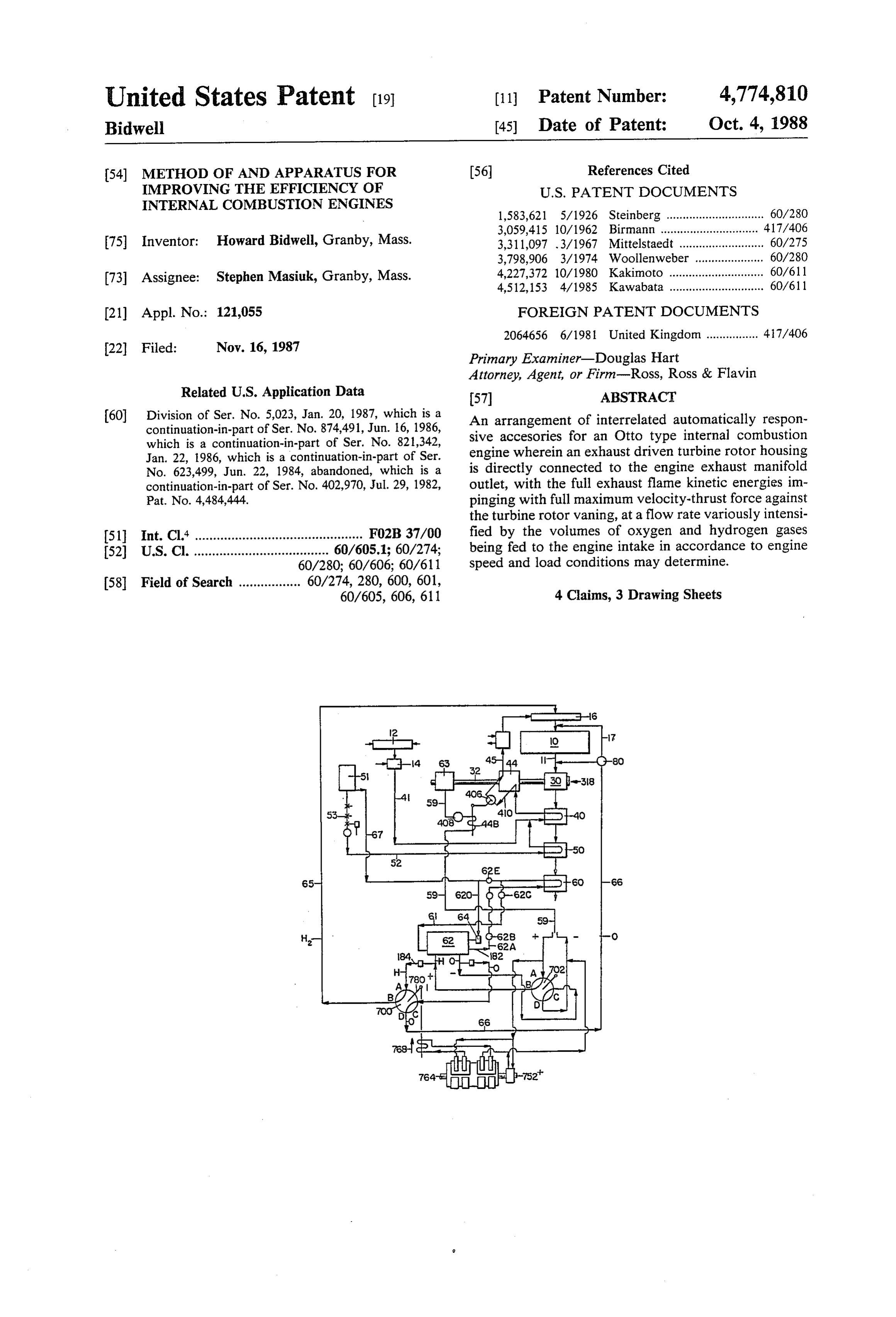
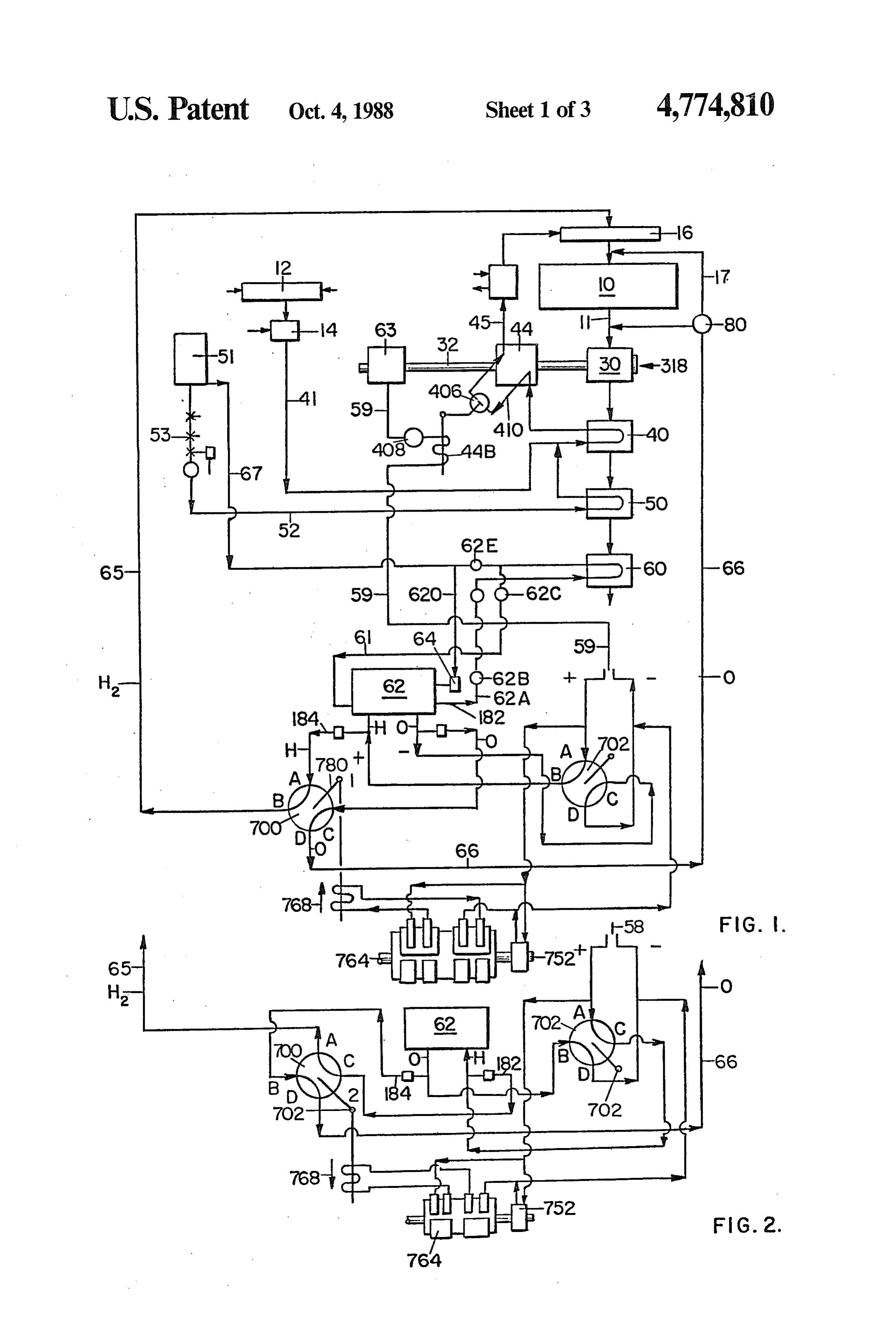
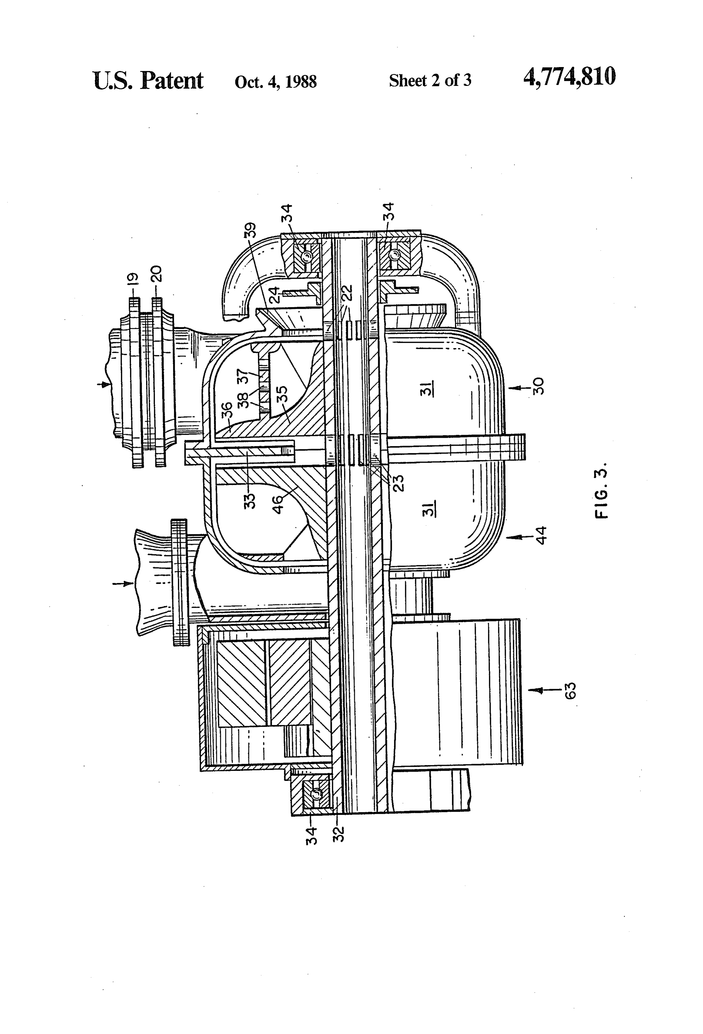
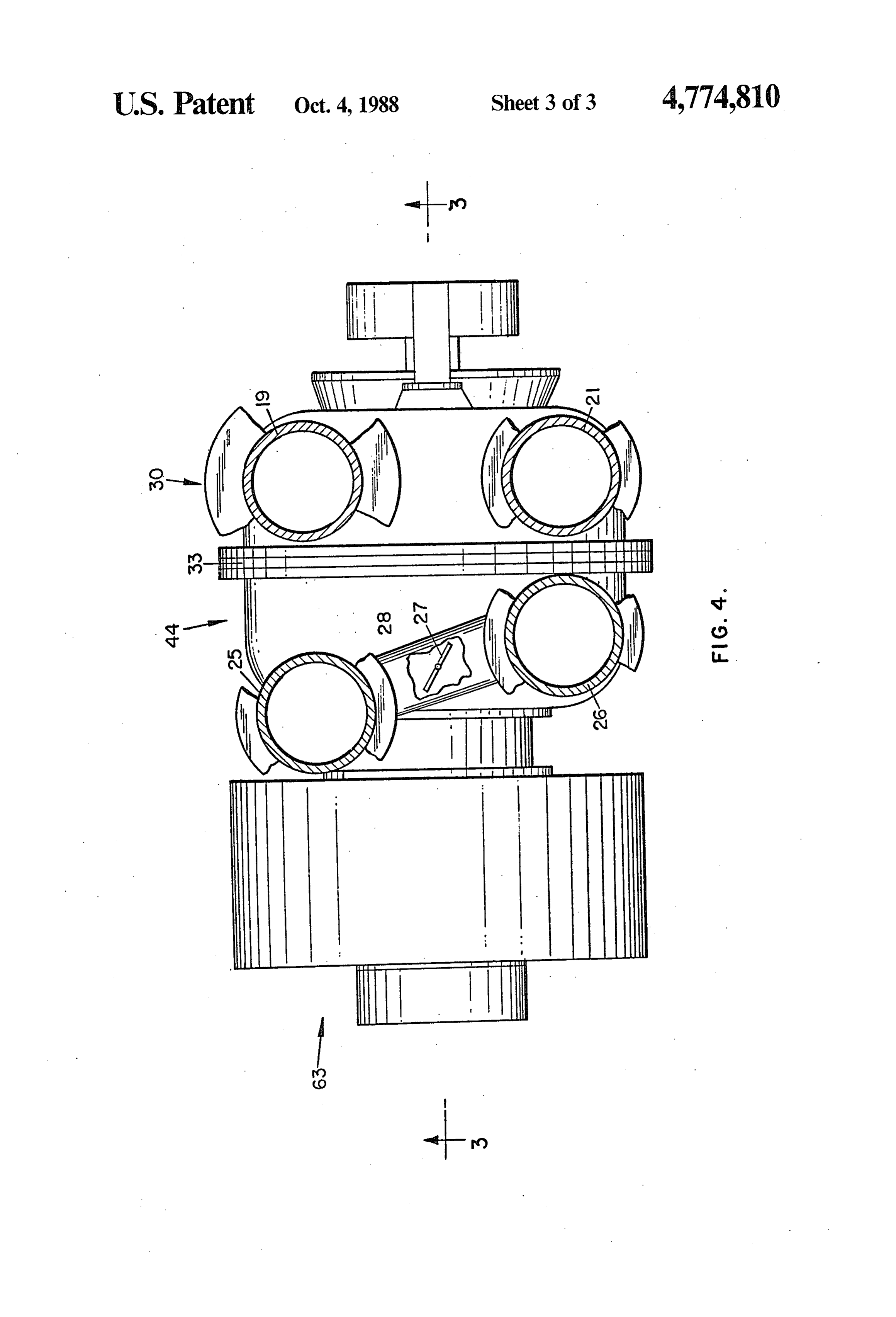
need for any switching or other controlling devices. The construction further utilizes the effective reac The gas generator is automatically responsive to en tionary vaning of the rotor and stator, not shown, of any ergization received from the electric generator which is type during the expanding gases of an induced second a special type of low voltage, high amperage generator, ary combustion activity resulting from a continuous designed for this particular service exclusively. flow of the super-heated auxiliary fresh air being con The electric current is directed through a suitable 45 stantly directed into the exhaust flame which is maxi electrical induction solenoid coil before reaching the mized throughout most of the rotor travel between the gas generator. Its intensity or amperage may be such as exhaust flame inlet to the outlet. to cause the armature within the solenoid coil to vary its BRIEF DESCRIPTION OF THE DRAWINGS position in response to that strength or amperage. The altering of the position of the armature is exploited via FIG. 1 is a schematic flow line diagram showing the a mechanical linkage to actuate the shutter position of a 50 various operatively interconnected components illus butterfly type bypass valve located between the inlet trating the basic principles of the invention; and outlet of a supercharger. FIG. 2 is a schematic flow line diagram showing the This arrangement allows the automatic control of the reversed positions of polarity of the electrodes; amount of carbureted air/fuel/mixture fed to the intake FIG. 3 is a part-sectional view online 3-3 of FIG. 4; manifold in consonance with the amount of hydrogen and 55 automatically fed alone, or the amounts of hydrogen FIG. 4 is a view in top plan of the FIG. 3 showing and oxygen automatically fed unisonly, to the intake, illustrating free of any regulating devices save for the usual throttle valve in partthewithrelative other arrangement of the by-pass components.
means for accommodating to the various engine speed and load conditions. 60 DESCRIPTION OF THE PREFERRED Advantageously, this arrangement is achievable EMBODIMENT without any dictate for change in the conventional In the schematic flow line diagram of FIG. 1, the carburetor and liquid type fuel supply systems or engine exhaust from the exhaust manifold outlet of an internal speed governing means.
2. Description of the Prior Art 65 combustion engine 10 is directed on to an air-cooled, No method or apparatus is known to exist for intensi exhaust exhaust-driven, turbine rotor within component 30, the fying what I identify as the secondary combustion of an flame impinging directly against the vaning of engine exhaust in combination with generating hydro the rotor and imparting a rotative motion thereto.
Page 6
The air-fuel mixture to the intake of engine 10 is This arrangement allows the automatic control of the drawn from an air filter 12 and cooperant carburetor i4, amount of carbureted air/fuel/mixture fed to the intake via a line 41, through a heat exchanger 40 to a super manifold in consonance with the amount of hydrogen automatically fed alone, or the amounts of hydrogen charger 44, passing therefrom, via a line 45, to an intake manifold 16 of engine 10. and oxygen automatically fed unisonly, to the intake, The carbureted air-fuel mixture delivered to the in free of any regulating devices save for the usual throttle take is thus heat conditioned by means of heat ex means for accommodating to the various engine speed changer 40 from which it is drawn through the inlet of and load conditions.
supercharger 44 by virtue of the drive shaft rotation, O Advantageously, this arrangement is achievable being then forced outwardly of the supercharger outlet, without any dictate for change in the conventional through a cooler, if one is provided, and thence to the carburetor and liquid type fuel supply systems or engine intake manifold. speed governing means
A water-alcohol solution is trickled from a reservoir Secondary combustion activity is created within tur 51, via a conduit 52, along which controls 53 are dis 15 bine 30 under the high operating temperature as auxil iary air is continuously fed directly into the engine posed, for regulating the flow in seriatim through a heat exhaust flame.
exchanger 50, heat exchanger 40, and supercharger 44 where the solution is converted to superheated steam. I also provide a means for directing a flow of water Controls 53 will be automatically activated to open in from reservoir 51, or water and alcohol in combination case of a freezing temperature, via conduit 52 to heat position, upon switching the vehicle ignition to on posi exchangers tion, automatically returning to off position when the 20 supercharger 50 and 40, in series therewith, and thence to ignition is turned off. 44 for changing the fluid from a vapor Supercharger 44, and an electric generator 63 coaxial the carbureted steam state to a true state for aiding the converting of air-fuel mixture from a vapor to a gase therewith, are driven jointly by an air-cooled drive ous state prior to entering the engine intake. This is to shaft 32 of rotor 30. 25 allow a more complete in-cylinder flamability. Current from electric generator 63 is supplied, via a Further with reference to FIG. 1, I show one of the line 59, to an hydrogen-oxygen gas generator 62 for the positions of polarity of the electrodes feeding current to generation of hydrogen and oxygen gases, the hydrogen the gas generator.
gas being delivered to the intake manifold through a A reversal of this polarity to a second position is conduit 65 and the oxygen gas being delivered selec 30 desired tively through a conduit 66 directly into the exhaust from theingasorder to intermittently free the electrodes bubbles collecting thereon and is accom flame and/or through a conduit 17 to a position be plished by the slow rotation tween the intake manifold and the engine according to motor 752. The armature of of a switch 764 driven by a a solenoid 768 is caused to the setting of a distribution valve 80. reverse positions between what I identify as positions 1 As more hydrogen and oxygen gases are fed to the 35 and 2 due to the reverse in current flow direction. engine, less carbureted air-fuel mixture from carburetor Through a suitable mechanical linkage, the position 14 is demanded. The flow thereof is regulated by virtue of both a 4-way valve 700 and a rotating electric switch of a bypass valve 406 at supercharger 44 FIG. 1 and 27 702 are changed from one position and held at the other FIG. 4 in accordance with the electric current amper position until the next timed reversal takes place. In the age flow rate through an ammeter 408 and a solenoid meantime, as in FIG. 2 a positive current from a feed 44B to gas generator 62. cable 59 is caused to flow to rotatable switch 702 termi Liquid flow from reservoir 5, via a conduit 67, is nal Athence to terminal C, thence to gas generator 62 directed to a heat exchanger 60 and then, also via a manifold 182, thence via the series of cell electrodes and conduit 620 to gas generator 62 as controlled by a liquid electrolyte within the generator to exterior manifold levei controller 64 located adjacent the gas generator 45 184, thence to rotationable electric switch terminal B to for controlling its electrolyte level. terminal D thence to negative (-) conductor of the Included is a means 62C for selectively heating and cable 59, causing hydrogen gas to flow from gas genera maintaining the electrolyte temperature, through heat tor manifold 182 to 4-way valve port C and out port A extracted from the engine exhaust by way of heat ex to hydrogen gas line 65 while simultaneously causing changer 60 in seriatim. The arrangement calls for a SO oxygen gas to flow from gas generator manifold 184 to separate electrolyte recirculating circuit 62A fitted with 4-way valve port B thence out port D, thence to oxygen a circulating pump 62B and a sight feed glass and thence line 66, thereby maintaining the flow of one type gas to the adjustable temperature regulator 62C in a return flow in each separate gas line during the repeated polar loop independent of electrolyte feed line level control ity changes in electric current flow to the gas generator with a one way check valve 62E in electrolyte feed line 55 62, all by virtue of the electric current fed through the 67 between the level control line and the electrolyte separate circuit wherein the electric current energizing recirculating line takeoff, all so as to attain an increased solenoid coil 768 is periodically reversed by a slow gas generating capacity by what would otherwise be revolving reversing drum switch 764, driven by slow wasted heat emanating from the exhaust. speed gearhead motor 752. This causes a periodic rever The electric current is directed through a suitable 60 sal of the electric current flowing through solenoid coil electrical induction solenoid coil 44B before reaching 768 and its armature mechanically linked to positioning the gas generator, and its intensity or amperage may be lever 780 on the rotation of cylinder switch 764 from such as to cause the armature within the solenoid coil to one position to the other.
vary its position in response to that strength or ampero In FIG. 1, I show the second position of polarity of age. The altering of the arnature position is exploited 65 the electrodes feeding the current to gas generator 62. via the mechanical linkage 406 to actuate the shutter In FIGS. 3 and 4, I have shown the FIG. 1 an original position of a butterfly type bypass valve located be type turbine 30, supercharger 44 and electric generator tween the inlet and outlet of the supercharger 44. 63 as combined into a unitary structure, the components
Page 7
being disposed in a side-by-side, or back-to-back ar Bypass valve 27 in a bypass duct 28 between outlet 26 rangement. and inlet 25 (FIG. 4) of the supercharger serves as the Drive shaft 32 is supported by bearings 34 outboard automatic means for regulating the volume of super of its opposite ends and has unobstructed air entrance charged air-fuel mixture bypassed through the bypass openings at each end to allow the admission of ambient duct.
air thereinto. This in turn controls the volume of air-fuel mixture Drive shaft 32, of hollow air-cooled design, is shown drawn from the carburetor.
disposed in paralleism with the crankshaft of the engine. Bypass valve 27 may be automatically positioned in Exhaust driven turbine rotor is fixed thereto. accordance with the rate of electrical current generated An intake supercharger rotor 46 is also mounted on 10 by electric generator 63, as propelled by the turbine and the corresponding volume of the gas or gases generated the drive shaft in a back-to-back relationship with rotor in gas generator 62 and fed automatically to the engine 30, the two rotors being housed within a housing 31 and separated by a common plate 33 disposed between (FIG. 1).
This in turn determines the need for more or less housing half parts. carbureted air-fuel mixture in accordance to volume of The rotor has outer vaning 36 and inner vaning 35 15 hydrogen separated from each other by a cylinderical shell 37 conditions.gas fed to engine intake under varying load provided with through perforations 38. This controls the positioning of the armature respec The exhaust flame impinges directly against outer vaning 36, rotating the rotor at a high velocity within tive to current flow volume as such energizes the sole the flame. Inner vaning 35 draws fresh air through an 20 noid. An increase or decrease in the amperage flow through the solenoid causes the solenoid to actuate the air inlet 39 which air is agitated and heat conditioned by linkage the inner vaning before being charged through perfora open thesobypass as to position bypass valve 406 (FIG. 1) to responsively to the amperage fed to the tions 38 for blending with the exhaust flame and for travel through the U-shaped route to the housing dis gas generator by which the more hydrogen and oxygen charge outlet 21. 25 fed to the engine, the less air fuel mixture flow needed. Operationally, the exhaust flame from exhaust mani generator With the engine operational, hydrogen gas within the fold outlet 19 enters exhaust rotor housing inlet 20 so as flows to the engine intake manifold, free of to impinge the flame with a thrust against the outer any flow regulating controls or devices and at a rate in accordance with the engine speed. Simultaneously, the vaning 36, FIG. 4, causing the rotor within component oxygen 30 to rotate along with the rotor of supercharger 44, and 30 During gas freely flows to the engine exhaust manifold. idling or at no-load speeds, the hydrogen and causing electric generator 63 to rotate, with the gener oxygen generating rates are reduced responsively to the ated current flowing to the gas generator 62.
The exhaust flow follows a U-shaped course toward low electric current flow from the electric generator, a discharge outlet 21. also operating at that speed.
The blending results in a secondary combustion ac 35 byThe the outside fresh auxiliary air drawn into the rotor inner vaning is vigorously agitated and heat tivity for the burning of any non-burned hydrocarbons conditioned in the exhaust gases. And all at the same time the vari tions of the prior rotor to being forced through the perfora inner chamber so as to be uniformly ous parts of the rotor are kept from excessive heating, it being cooled in part by the air currents drawn into the distributed among the various vanes of the outer rotor vaning, and directly into the high temperature exhaust housing via a series of peripherally-arranged airports 22 flame blast. This excites an increased additional second in the drive shaft. Other air ports 23 in the drive shaft ary combustion activity and results in an increased gas allow a cooling of the back vaning 35 and 46 on the volume expansion respective backsides of the two rotors further aiding the rotor outer vaning.andSimultaneously velocity thrust force against the the unburned hy blending of the fresh air in the exhaust flame. drocarbons are burned so as to increase the carbon The fresh air being introduced via inlet 39 to the 45 turbine rotor initially flowing over the outer vaning dioxide content.
The operation is fully automatic without any need for surfaces while being blended into the flame due to the regulating controls since gas generation does not begin rotor rotation, helps to avoid a lowering of the exhaust until the engine exhaust has reached an intensity suffi flame temperature so as not to degrade the secondary combustion activity. Yet it is sufficient enough to in 50 to cient to drive the electric generator at a speed sufficient crease the propelling force on the outer vaning so as to inggenerate an electric current of a wattage for operat the hydrogen-oxygen gas generator at a capacity generate additional energy.
The charge of fresh air admitted to the turbine is rate in direct relationship with the engine load-speed controllable by a slidable shutter 24 mounted on the operation. I claim:
drive shaft 32 (FIG. 3). 55
Means is also provided for by-passing of a portion of 1. Fluid motor means driven by exhaust energy di the supercharged carbureted air-fuel mixture so as to rectly from an internal combustion engine manifold reduce the air fuel volume flow from carburetor 14, outlet including:
a turbine and supercharger and electric generator during periods when the hydrogen and oxygen gases are being fed to engine intake 16 or otherwise distrib 60 theaxially mounted on a drive shaft, turbine transferring the energy from the engine uted.
Intake supercharger inlet 25 receives the air-fuel mix exhaust to a motive fluid for rotating the drive shaft ture from conduit 41 (FIG. 1) which is then accelerated of the supercharger and electric generator, in its passage through the supercharger by virtue of the a source of an air/fuel mixture for delivery to the supercharger vaning before its discharge via super 65 a gas supercharger, charger outlet 26 (FIG. 4). generator automatically energized by the total Between inlet 25 and outlet 26, a butterfly type by electric generator output exclusively upon the ro pass valve 27 (FIG. 4) is disposed as 406 (FIG. 1). tation thereof,
Page 8
an induction solenoid coil in the power line between current flow from the electric generator to the gas the electric and gas generators with a solenoid generator.
armature being shiftable responsively to the amper 3. In an internal combustion engine including an ex age of the current in the power line to the gas 5 haust propelled system for carrying exhaust fluid from generator, the engine and a turbine adapted to utilize energy in the a valved by-pass disposed between the inlet and out exhaust fluid, wherein the improvement comprises: a source of an air/fuel mixture, let of the supercharger, a mechanical linkage between the armature and a a supercharger connected with the exhaust propelled valve of the by-pass, system and adapted to utilize energy in the exhaust with the air/fuel mixture fed to the engine being
O fluid for increasing the pressure of the air/fuel automatically variable according to the quantities mixture delivered from the source to the super charger, of oxygen and hydrogen fed to the engine intake an electric generator driven by the exhaust system, a and with the pressure and volume of the air/fuel gas generator energized by the electric generator mixture flowing from the supercharger to the en 15 for generating hydrogen and oxygen gases, gine being at a rate in consonance with the separate delivery means for separately delivering hydrogen selected flow of oxygen and hydrogen to the en and oxygen gases to the engine, gine intake. delivery means for delivering the air/fuel mixture 2. In an internal combustion engine having an exhaust from the supercharger to the engine for reaction driven turbine, the improvement in apparatus for auto 20 with the hydrogen and oxygen gases, matically controlling a sequenced series of events in a valved bypass in the supercharger connected with volving a plurality of interrelated components includ the supercharger inlet and outlet with a valve in the Ing: bypass being mechanically and electrically respon a supercharger driven by the turbine, sive to the amperage value flow in the power line a valved by-pass within the supercharger between the 25 between the electric and gas generators. inlet and outlet thereof, 4. In a multi-component interconnected automatic an electric generator driven by the turbine, responsive internal combustion engine waste heat recla means for creating an variable air/fuel mixture for mation system, comprising the steps: delivery from the supercharger to the engine, automatically feeding hydrogen gas to the engine means for trickling water to the supercharger for 30 intake for reducing the volume of the carbureted conversion into super heated steam for facilitating liquid fuel/air mixture intake in consonance with feeding oxygen gas selectively as allowed by the the converting of the air/fuel mixture to a gaseous increased maximum extracting of velocity and heat state, energies, boosted in part by a selected variable a gas generator energized by the electric generator 35 quantity volume flow of oxygen gas enriched en for creating supplies of hydrogen and oxygen gases gine exhaust jet expanded directly against vaning with the hydrogen gas being separately delivered of an exhaust driven auxiliary air inducing and heat to the engine intake and with the oxygen gas being conditioning rotor, the rotor in turn propelling a separately delivered to the exhaust turbine inlet, supercharger rotor and a direct connected low an ammeter and solenoid in the current line extending voltage high amperage D.C. electric generator for from the electric generator to the gas generator, respectively supercharging the engine intake con a mechanical linkage operated by the solenoid and tent and energizing a hydrogen-oxygen gas genera connected to a valve in the by-pass for actuating tor, altering the engine intake content while simul the valve and therewith controlling the amount of taneously altering the exhaust content by increas the air/fuel mixture fed to the engine in consoe 45 ing the exhaust velocity thrust against the rotor nance with the volume of hydrogen and oxygen vaning, simultaneously blending heat conditioned fed to the engine, auxiliary air directly into the exhaust for addition ally increasing the secondary combustion activity the above-recited elements being adapted and ar within the exhaust turbine rotor and thereby ob ranged foir lessing the floe of air/fuel mixture to 50 taining additional thrust against the rotor vaning the engine as the charges of hydrogen and oxygen while consuming the unburned hydrocarbons to a gases are increased as regulated by the valve in the maximum CO2 content.
by-pass in the supercharger responsively to the sk k 2K k
Provenance
- Collection
- Cited prior art
- Original PDF
- patentimages.storage.googleapis.com →
- Filed
- 1987-11-16
- Pages
- 8
- Method
- pdftotext (the PDF's own text layer) + pdftoppm 300dpi page scans
- Source
- Google Patents bibliographic record
- Granted
- 1988-10-04
- Inventors
- Howard Bidwell
- Transcribed from
- patentimages.storage.googleapis.com →