patent · US1996023
Electric motor
26 March 1935
Page 1
Drawing sheet — no readable text.
Page 2
Drawing sheet — no readable text.
Page 3
March 26, 1935. J. D., MacLACH LAN 1,996,023
ELECTRIC MOTOR
Filled June 29, 1933 3 Sheets-Sheet 3 tith th
EEEEEEEEEEECC
itSEEEEEEEEEE
votor Zave Zs-->
EREC
EEE,
XXS.
- -- A Zap. Ol --
C. P. P. D. R. R. Rol C see
Page 4
Patented Mar. 26, 1935 1996,023
UNITED STATES PATENT OFFICE
ELECTRIC MOTOR
John D. MacLachlan, Kansas City, Mo., assignor to Mac Ad Company, Kansas City, Mo., a cor poration of Missouri
Application June 29, 1933, Serial No. 678,168
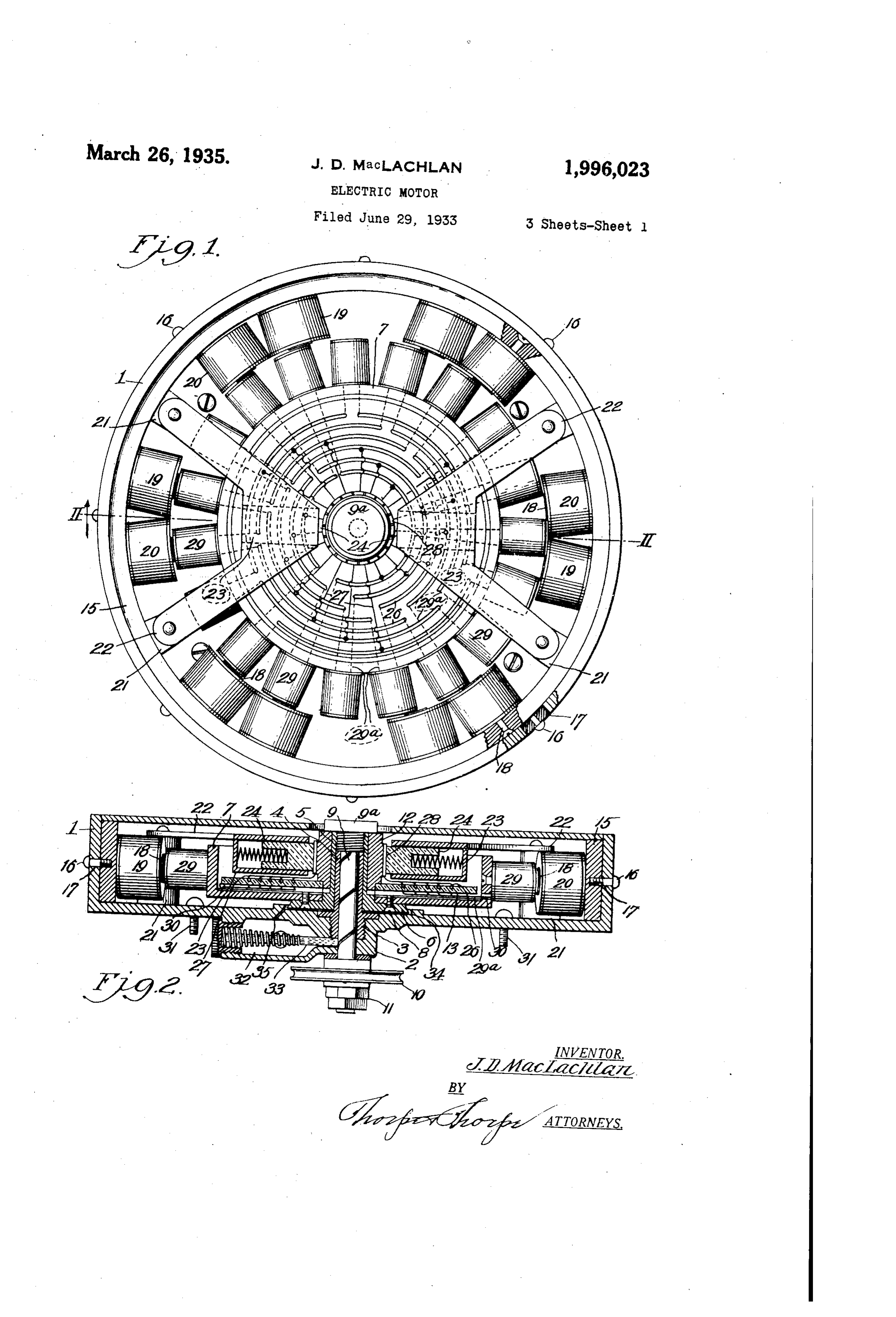
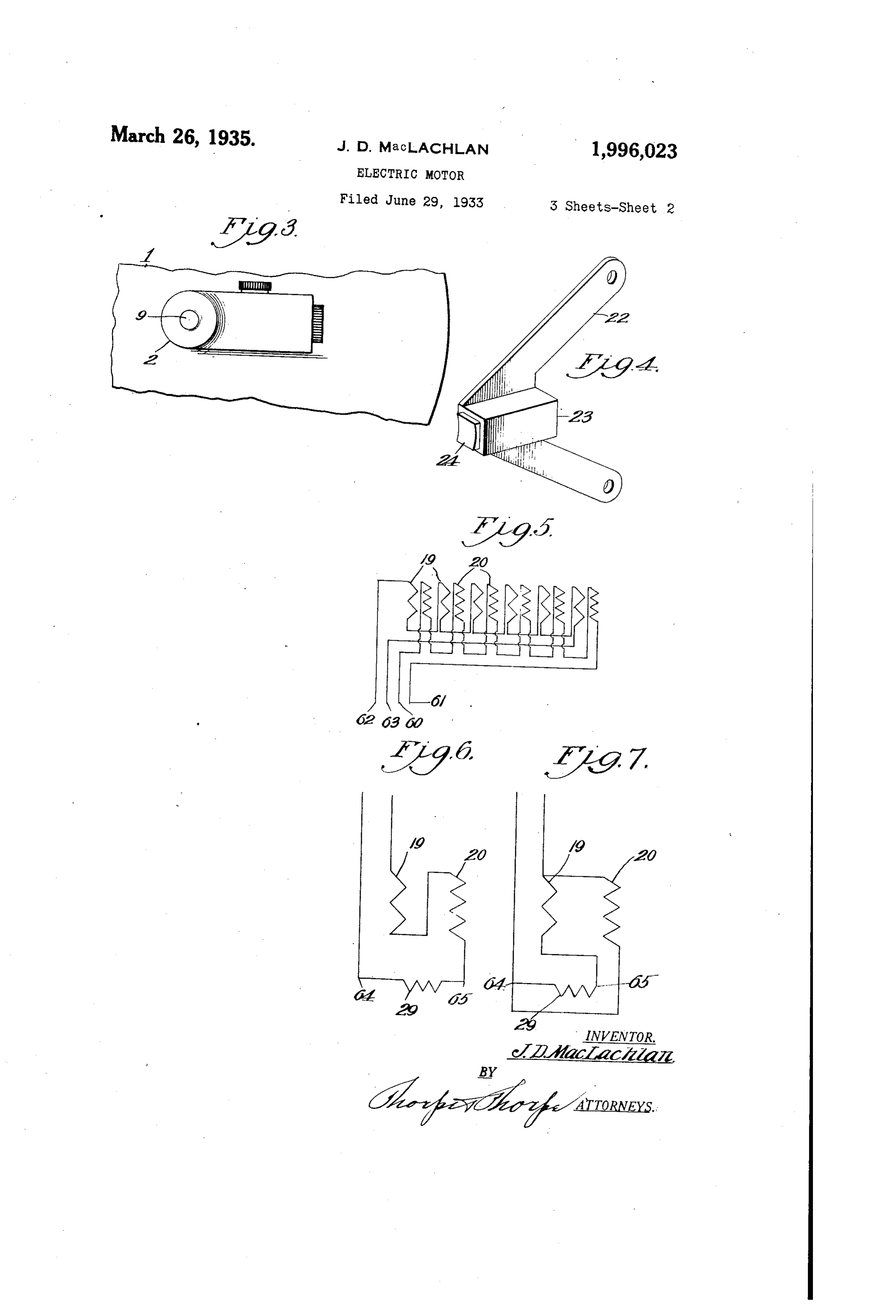
This invention relates to universal motors and Figure 2 is a section on the line II-II of Fig my general object is to produce a motor which lure 1.
will have relatively constant speed on either A. C. Figure 3 is a fragmentary side elevation of the Or D. C. current of the same voltage, when the cir closed end of the electric motor. 5 cuit connections are made in a predetermined Figure 4 is a perspective view of one of the manner, regardless of the load, the object being brush holders.
accomplished by the production of a construction Figure 5 is a diagrammatic view of One method in which the stator is divided into a multiplicity of connecting the multi-field coils in separate of Sets of field poles arranged in groups of the Series,
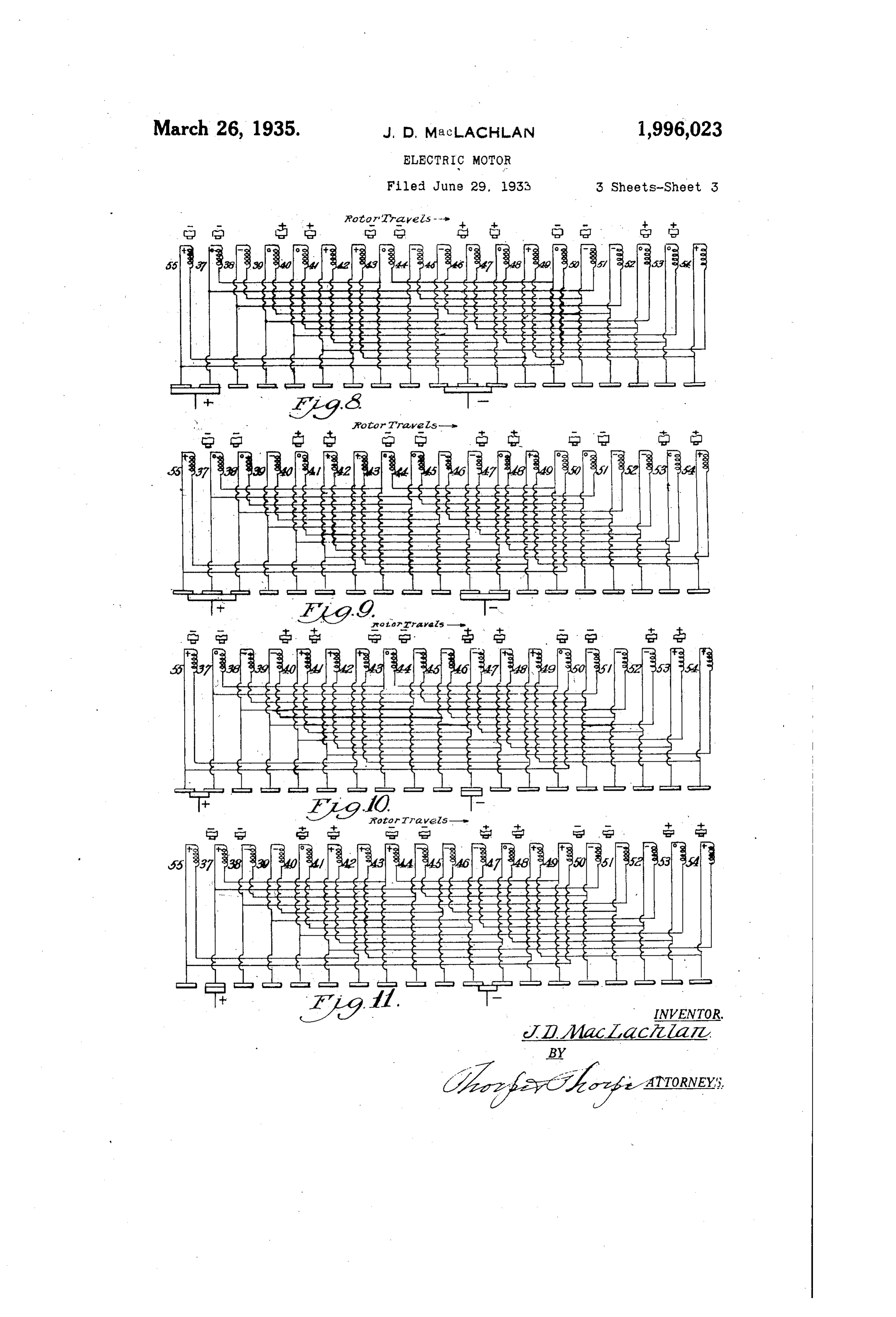
O same polarity, but preferably of different resis Figure 6 is a diagrammatic view of a straight O tance, whereby it is possible to use the entire Series connection for running on D. C. current. Stator windingS in Series. With the rotor when op Figure 7 is a diagrammatic view of a series erating On D. C., and then, when desiring to oper shunt connection for running on A. C. current. ate on A. C., to shunt One or more groups of field Figure 8 is a diagrammatic view of the motor poles, aS will hereinafter appear. By properly With the Stator, rotor and commutator segments 5 proportioning the windings, a universal motor is as they Will appear with brushes of the width thus produced, which operates at substantially of two commutator segments, the energization the same speed and power output with direct cur of the parts being also illustrated, rent and with alternating current of the rated Figure 9 is a view similar to Figure 8, but shows 20 voltage. the rotor just before it has turned to the posi 20 Another object of the invention is to produce tion shown in Figure 8.
a construction in which the rotor coils are inde Figure 10 is a diagrammatic view of the motor pendent of each other and are readily accessible With the stator, rotor and commutator segments for replacement or repair without necessitating as they will appear with brushes of the width of 25 interference with other coils, making it possible One commutator Segment, the energization of the 25 to use Solid iron cores with a consequent material parts being also illustrated. Saving in cost of manufacture, although, of course, Figure 11 is a view similar to Figure 10, but laminated coils may be employed where found shows the rotor just before it has turned to the desirable. position shown in Figure 0. 30 A still further object of the invention is to pro In the preferred construction, 1 indicates a 30 duce a Spool wound rotor in order that the large drum-shaped casing, open at one of its sides and Volume of magnetically non2effective wire at the provided with a central internally threaded stud ends of the rotor as in the ordinary type of drum or boSS 2 receiving a bushing 3. The bushing pro Winding, shall be avoided. In the ordinary drum jects into the Space within the casing 1 to form 35 Winding Substantially 20% to 30% of the Wind a hollow spindle 4. Journaled on the spindle 4 35 ing is at the opposite ends of the rotor. is a sleeve 5 formed adjacent the closed end of Another object of the invention is to produce the casing With an annular flange 6, to which a a motor which is cheaper to manufacture and Second drum-shaped member 7 of smaller diame less expensive to repair than standard motors, ter and open at one side, is secured by bolts 8. 40 and which will not overheat when in Service. The Second drum 7 forms the spider or frame of 40 A still further object of the invention is to pro a rotating armature as will hereinafter appear. duce an electric motor of new construction which To hold the Second drum in position, one end is adapted for use in a confined space and is of sleeve 5 projects beyond the spindle 4 and is equipped with a force feed lubrication system re internally threaded for engagement with threads quiring but infrequent attention. formed on a pin or shaft 9, having a head 9a, 45 With the general objects named in view, and and projecting through the spindle 4 and others as will hereinafter appear, the invention equipped at its opposite end, externally of the consists in certain novel and useful features of closed end of the casing 1, . with a power take construction and Organization of parts as here off pulley or the like 10. The pulley is held to 50 inafter described and claimed; and in order that the shaft and the shaft is held against displace 50 it may be fully understood, reference is to be had ment by a Series of lock nuts 11, threaded on the to the accompanying drawings, in which:- end of the shaft 9. Pressed or otherwise secured Figure 1 is a side elevation with the housing to the sleeve 5 and held by the head 9a, is a plate omitted, of an electric motor embodying the commutator 12 and a distributor disk 13, the disk 55 invention. here shown being in the form of a flat plate, 55
Page 5
which shape, however, depends on the motor de inner face of the casing 1, and from thence re sign. It may obviously be of any desired shape turns by an opening 35 into the well or oil res as will hereinafter appear. ervoir.
Rotatably adjustable within the casing is With the construction described, it is apparent a ring 15, held in position, by bolts 16 passing that the entire armature may be removed from through slots 17 in the casing 1. The ring 15 the open side of the drum by the removal of in the type of motor illustrated, carries a series the brushes and the withdrawal of the headed of radially arranged bolts 18, each bolt being shaft 9, or that the field coils may be as readily re the core of a field coil, or the coils may be secured moved by the Withdrawal of the adjusting clamp O in any other manner. The coils are positioned ing bolts 16. 10 in adjacent pairs as here illustrated, although One type of armature connection is shown dia they may be in triplex, quadruplex, etc., and al grammatically in Figure 8, the armature coils be though each separate coil may be of the same re ing respectively numbered 37 to 55 inclusive, with sistance, if desired. It has been found that by One of the brushes 24 connected to the positive 5 making the coils 20 (the rearward coils in the side of a source of direct current and in contact 5 direction of rotation), of higher resistance than with the commutator segments (which corre the coils 19, whereby by properly proportioning spond in number to the number of armature the resistance of the coils the entire stator wind coils), leading to coils 37 and 55, and the other ings may be connected in series with the rotor brush 24 being connected to the negative side 20 When Operating on D. C., and then, when de of the line and contacting with the com 20 siring to operate on A. C., one of the groups of mutator segments connected to coils 45,46 and 47. field coils may be shunted to alter the resistance In the construction illustrated, where it will be of the motor. If the parts are properly propor noted the brushes are the width of two commutator tioned, the speed and power output will remain segments, arnature coils 37, 43, 49, 46, 52, 39, and substantially the same with both types of current 40, 53, 47 will be neutral or dead; coils 55, 42, 48, of the same voltage. The effect is to produce a 54 and 41 will be positive; and coils 45, 51, 38, 44 universal motor by weakening the field strength and 50 will be negative.
when operating on A. C. Another method of ac However, if the brushes shown in said figures complishing this result is shown in the patent to are reduced to one commutator segment in width, 30 Lamme, No. 1,244,511, issued October 20, 1917. it will be found that with the connections illus 30 The brush carrying frame in the construction trated in Figure 10, armature coils 37, 43 and 49 here illustrated, comprises two pairs of insulating are neutral, or just at the point of current re members 2 secured to the inner face of the closed verse, while coils 38, 39, 44, 45, 46, 50, 51 and 52 end of the casing i, and a pair of V-shaped rigid are negative, and coils 40, 41, 42, 4, 48, 53, 54. conductor straps 22 carried by said insulating and 55 are positive the current reverse always blocks 21, the adjacent ends of the straps being occurring in three coils simultaneously, it being provided with sockets 23 from which spring understood that the position of the armature advanced brushes 24 project, said brushes in the coils shown in Figure 1, corresponds to the preferred construction, as illustrated in Figures diagrammatic position of Said coils shown in Fig 40 10 and 11, being of Sufficient Width to simultane ures 8 and 10. In Figure 9 the rotor occupies a 40 ously cover not more than one commutator Seg position just before it has turned to the position ment. shown in Figure 8, and rotor coils 55, 41, 42, 48 The distributing insulating disk 13 is formed and 54 are positive, coils 39, 45, 46, 51 and 52 are With a series of segmental slots in which are em negative, and coils 37, 38, 40, 43, 44, 47, 49, 50 45 bedded or otherwise Secured, suitable conducting and 53 are neutral. In Figure 11, the rotor has straps or bars 26, each conductor being connected not yet turned to the position shown in Figure by a low resistance lead 27 to a commutator seg 10, and the rotor coils 55, 37, 41, 42, 43, 48, 49 and ment 28. Besides its connection to a commutator 54 are positive, coils 38, 39, 44, 45, 46, 50, 51 and Segment, each conductor 26 is also connected by 52 are negative and coils 40, 47 and 53 are neutral. 50 Wires 290 to the opposite ends of a pair of arma For convenience in making various connections 50 ture coils 29, arranged in radial positions around or hook-ups of the motor, the terminals of each the circumference of the member 7. The flange set of coils on the field and of the rotor, are placed of the armature spider. 7 is provided with in at an easily accessible location. The field coils sulating bushed openings 30, through which the 19 as illustrated may be connected in Series as 55 leads to the armature coils extend. shown in Figure 5, each set of coils forming a 55 The motor as illustrated, has nineteen arma separate series, and their terminals being re ture coils and six pairs of independent field coils, spectively indicated at 60 and 61, for the coils each with its individual pole piece. The pre 20, and 62 and 63 for the coils 19. The brushes ferred direction of rotation is clockwise, although are provided with suitable terminals (not shown), O it is evident that the motor will run with equal and it will be understood that each of the leads 80 facility in either direction. The motor may be is properly insulated.
secured in position to any suitable support by a With the general type of construction here series of bolts 31 projecting through its closed shown it will be evident that all of the coils are Side, Figure 2. o entirely independent of the other coils and that 65 To provide a permanent method of lubrication if a short circuit develops in any of the coils of 65 so that the motor may be operated for long periods the field or rotor, the entire coil-may be readily of time without attention, the rear exterior face removed by simply disconnecting its two termi of the casing 1 carries an oil or lubricant well 32, nas, and that a new coil may be as readily Sup and extending from said Well into contact with plied. It will be further noted that a multiplicity 70 the shaft 9 is a feed wick 33. The shaft 9 is of hook ups for the motor may be employed, the 70 spirally fluted to feed the oil outwardly between method of connecting the rotor coils through the said shaft and the spindle 4, whence it returns distributor being used to advantage in manufac between the external face of the Spindle 4 and ture, as coils of predetermined capacity may be the sleeve 5, and is thrown out by centrifugal made in standard sizes and standard distributor s force into a circular chamber 34 formed On the disks may be proced. When a motor of prede 75
Page 6
termined characteristics is desired, such stock of casing in axial alinement therewith, a rotating parts may be selected and the connections made arnature journaled in said bushing, and a rotat on the distributor Without having to produce spe ing headed shaft extending through the bushing cial windings as required under present condi and rotating with and retaining the armature in 5 tions for every type of motor. - position.
In Figure 6, the motor is diagrammatically 3. In an electric motor, the combination of a shown as connected in straight series for use on drum-shaped casing, a series of radially arranged direct current. In Figure, it is shown in series field coils projecting from the inner face of the shunt for use on alterrating current, the high casing, a bushing carried by the closed side of the O resistance field coils being shunted around the casing and in axial alinement therewith, a drum O low resistance field coils and the rotor. It is found shaped armature spider journaled on the bush that the pole strength is still substantially the ing, a series of armature coils carried thereby, same as all of the windings are being used, and a commutator in cooperative relation to the ar the motor as thus connected in an A. C. circuit of mature spider, and a distributing member inter the same voltage as in the D. C. connections, will posed between the commutator and the armature produce substantially the same speed and power. spider and provided with connecting bars respec It is to be understood that while I have de tively connected to the commutator segments and scribed what now appear to be the preferred em to the armature coils.
bodiment of the invention, I reserve the right to 4. In an electric motor, the combination of a 20 all changes within the spirit of the invention, and drum-shaped casing, a series of field coils pro 20 Without the ambit of the prior art. jecting inwardly from the inner periphery of the I claim:- casing, a hollow bushing projecting inwardly 1. In an electric motor, the combination of a from the inner face of the casing and in axial rotating armature, a series of equi-spaced similar alinement therewith, a rotating armature jour coils carried by Said armature, and a field com naled on said bushing, a spirally fluted rotating prising a plurality of independent electro-mag shaft extending through the bushing and retain nets of the same polarity arranged in coacting ing the armature in position, a lubricant con groups to simultaneously affect the same arma tainer carried by the exterior side of the drum, ture coils, the independent coils of each group means to feed lubricant to the fluted shaft, a being of different electro-magnetic strength, said lubricant discharge passage between the inner 30 groups being equally spaced and every other side of the drum and the armature, a circular group being of opposite polarity. recess in the inner face of the drum to catch the 2. In an electric motor, the combination of a discharged lubricant, and a drain passage from casing, a drum-shaped rotor, a series of field coils said groove to the lubricant container. 35 projecting inwardly from the inner periphery of 35 the casing, a hollow bushing projecting into the JOHN D. MACACHLAN.
Provenance
- Collection
- Cited prior art
- Original PDF
- patentimages.storage.googleapis.com →
- Filed
- 1933-06-29
- Pages
- 6
- Method
- pdftotext (the PDF's own text layer) + pdftoppm 300dpi page scans
- Source
- Google Patents bibliographic record
- Granted
- 1935-03-26
- Inventors
- John D Maclachlan; MAC AD Co
- Transcribed from
- patentimages.storage.googleapis.com →