patent · US4755305
Continuous dewatering method
5 July 1988
Page 1 — bibliographic record
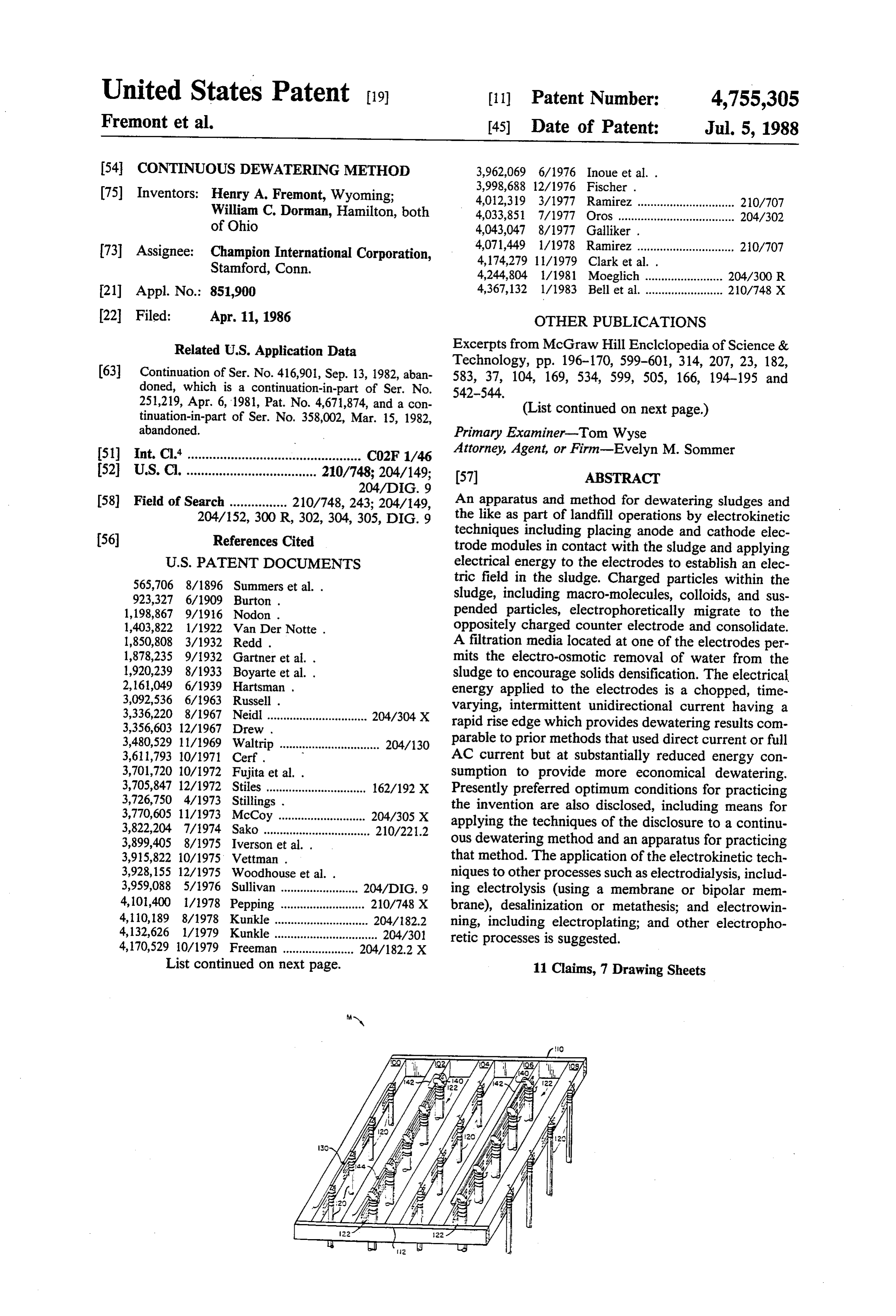
United States Patent (19) 11) Patent Number: 4,755,305 Fremont et al. 45) Date of Patent: Jul. 5, 1988 54 CONTINUOUS DEWATERING METHOD 3,962,069 6/1976 Inoue et al. . (75) Inventors: Henry A. Fremont, Wyoming; 3,998,688 12/1976 Fischer. 4,012,319 3/1977 Ramirez .............................. 210/707
William C. Dorman, Hamilton, both 4,033,851 7/1977 Oros .................................... 204/302 of Ohio 4,043,047 8/1977 Galliker .
73 Assignee: Champion International Corporation, 4,071,449 1/1978 Ramirez .............................. 210/707 Stamford, Conn. 4,174,279 11/1979 Clark et al. .
21) Appl. No.: 851,900 4,367,132 l/1983 Bell et al. ........................ 210/748 X 22 Filed: Apr. 11, 1986 OTHER PUBLICATIONS Related U.S. Application Data Excerpts from McGraw Hill Enclolopedia of Science &
(63) Continuation of Ser. No. 416,901, Sep. 13, 1982, aban 583, 37, 104, 169, 534, 599, 505, 166, 194-195 and doned, which is a continuation-in-part of Ser. No. 542-544.
251,219, Apr. 6, 1981, Pat. No. 4,671,874, and a con (List continued on next page.)
abandoned. Primary Examiner-Tom Wyse 51) Int. Cl." ................................................ CO2F 1/46 Attorney, Agent, or Firm-Evelyn M. Sommer 52 U.S. C. .................................... 210/748; 204/149; (57) ABSTRACT
58) Field of Search ................ 210/748, 243; 204/149, An apparatus and method for dewatering sludges and 204/152, 300 R, 302, 304, 305, DIG. 9 the like as part of landfill operations by electrokinetic
techniques including placing anode and cathode elec trode modules in contact with the sludge and applying
565,706 8/1896 Summers et al. . tric field in the sludge. Charged particles within the 923,327 6/1909 Burton. sludge, including macro-molecules, colloids, and sus 1, 198,867 9/1916 Nodon . pended particles, electrophoretically migrate to the 1,403,822 1/1922 Van Der Notte. oppositely charged counter electrode and consolidate. 1,850,808 3/1932 Redd. A filtration media located at one of the electrodes per 1,878,235 9/1932 Gartner et al. . mits the electro-osmotic removal of water from the 1,920,239 8/1933 Boyarte et al. . sludge to encourage solids densification. The electrical 2,161,049 6/1939 Hartsman . energy applied to the electrodes is a chopped, time
3,336,220 8/1967 Neidl ............................... 204/304X rapid rise intermittent varying, edge which unidirectional current having a provides dewatering results com
3,480,529 11/1969 Waltrip ......................... 204/130 parable to prior methods that used direct current or full 3,611,793 10/1971 Cerf . AC current but at substantially reduced energy con 3,701,720 10/1972 Fujita et al. . sumption to provide more economical dewatering. 3,705,847 12/1972 Stiles ............................... 162/192 X Presently preferred optimum conditions for practicing 3,726,750 4/1973 Stillings . the invention are also disclosed, including means for 3,770,605 11/1973 McCoy ........................... 204/305 X applying the techniques of the disclosure to a continu 3,822,204 7/1974 Sako ................................. 210/221.2 ous dewatering method and an apparatus for practicing
3,915,822 10/1975 Vettman. that method. The application of the electrokinetic tech 3,928, 155 12/1975 Woodhouse et al. . niques to other processes such as electrodialysis, includ 3,959,088 5/1976 Sullivan ........................ 204/DIG, 9 ing electrolysis (using a membrane or bipolar mem 4,101,400 1/1978 Pepping ... ... 210/748 X brane), desalinization or metathesis; and electrowin 4,110,189 8/1978 Kunkle ...... ... 204/182.2 ning, including electroplating; and other electropho 4,132,626 l/1979 Kunkle................................ 204/301 retic processes is suggested.
List continued on next page. 11 Claims, 7 Drawing Sheets
Page 2
Drawing sheet — no readable text.
Page 3
Drawing sheet — no readable text.
Page 4
Drawing sheet — no readable text.
Page 5
Drawing sheet — no readable text.
Page 6
Drawing sheet — no readable text.
Page 7
Drawing sheet — no readable text.
Page 8
Drawing sheet — no readable text.
Page 9
CONTINUOUS DEWATERING METHOD
sustaining the applied electric field. In the past, direct current has been applied to the electrodes to establish
CROSS REFERENCE TO RELATED
the electric field. Direct current has the advantage of
APPLICATIONS
establishing a uniform field but has the associated disad vantage of not being readily available from power
This application is a continuation of application Ser. mains and, accordingly, must be generated on site, usu No. 416,901, filed Sept. 13, 1982, abandoned, which is a ally through motor-generator sets. Experience indicates continuation-in-part application of Ser. No. 251,219, that the dewatering rate, that is, the rate of water re filed Apr. 6, 1981, U.S. Pat. No. 4,671,874 and a con moval over time, or conversely, the rate of solids con tinuation-in-part application of Ser. No. 358,002, filed O solidation, is roughly proportional to the power con Mar. 15, 1982, abandoned, both by the inventors of this sumed in kilowatt hours (KWH). The economic costs application and assigned to the assignee of the subject associated with dewatering an acre of sludge as part of improvement. a landfill operation are presently between $8500-$9500
(1980 dollars). Accordingly, there is an economic need to effect dewatering by electrokinetic techniques at
The present invention relates to the dewatering of substantially reduced electrical energy costs. sludges, slurries, or the like, that contain macro In addition, there is a continuing need in the art of molecules, colloidal particles, and/or suspended parti electrokinetic dewatering to dewater sludges continu cles in a carrier liquid, usually water, and, more particu ously in a rapid, cost-effective manner, in situ, to ease larly, to dewatering of such materials using electroki 20 netic techniques including both electrophoretic and the burden of sludge handling and disposal of material reclamation. In addition, it is desirable to be able to electro-osmotic techniques.
In addition, this invention relates to the application of ances readily toconventional adapt existing continuous sludge convey the electrokinetic techniques disclosed to such electro It is toward the solution of these aspectsofofthis utilize the techniques invention.
kinetic processes as electrodialysis, including electroly 25 that this application is directed, as well as to theproblems the applica sis, desalinization, and metathesis; and electrowinning; tion of the techniques described in the parent case to a as well as to electrophoretic processes other than the continuous dewatering system.
dewatering of sludges and slurries. In addition to the application of the teachings of this Many industries, especially the paper making and related fiber production industries, generate large quan 30 invention to electrophoretic dewatering of liquid of the tities of sludge or slurry-like effluents that contain vari type which includes emulsions, slurries, and solutions, ous concentrations of materials generically described as the advantages of the invention are expected to be ob "solids' that can include, for example, dispersed and tained for the electrophoretic treatment of such compo semi-dispersed macro-molecules, colloidal particles, sitions as polyvinyl acetate, polyvinyl chloride, and and suspended particulate matter. As part of the treat 35 other compounds manufactured, purified or treated ment of the effluents, the liquid carrier or water is sepa using electrophoresis. Thus, it is expected that the appli rated from the solids with the so-separated water being cation of a time-varying, intermittent, unidirectional recycled to the industrial process or returned to the current, having the wave form here described, to cath environment and the solids disposed of through landfill ode and anode electrodes minimizes the consumption of operations. power in electrophoretic processes experiencing the In the past, the dewatering of effluents to isolate phenomenon of migration of suspended or colloidal solids has been accomplished by thermal evaporation, particles in a liquid due to an emf or potential applied to mechanical filtration, chemical processing, settling, the electrodes.
flotation, and a variety of other methods. In some spe In addition to its application to electrophoretic pro cial cases, electrical dewatering of effluents and sludges 45 cesses, it is expected that the invention may also be used has been accomplished by establishing an electric field with processes using electrodialysis and electrowinning. in the sludge between electrodes immersed within the Examples of types of electrodialysis processes to which sludge. As a consequence of the applied electric field, the invention can be applied are processes using elec particles within the sludge that carry a net positive or trolysis, whether using a membrane process or a bipolar negative charge, including macro-molecules, colloidal 50 membrane, such as in the manufacture of chlorine or particles, and suspended particles, electrophoretically chlorination processes; desalinization processes, espe migrate to their respective, oppositely charged, counter cially those using a membrane; and metathesis pro electrode. In addition to the migration of the particulate cesses. An example of metathesis is the typical reaction: matter, water molecules which are bound to or other CAOH2--2NACL=CACL2-2NAOH.
wise associated with some of the charged particles will 55 Electrolysis or electrolytic conduction, for purposes co-migrate with those particles. As a consequence of of the application of the teachings of this invention, can this migration of charged particles and associated water be considered to be the conduction of electricity ac molecules, the solid particles consolidate and densify to companied by the actual transfer of matter, i.e. migra effect partial separation from the liquid carrier. Filtra tion of ions, which is shown by the occurrence of chem tion devices can be provided at or near one of the elec ical changes at the electrodes.
trodes to permit removal of the water by electro Electrowinning is the recovery of metals from ores osmotic techniques. With continued application of the by electrochemical processes and is also known as elec electric field and water removal, the solids concentra tro-extraction. In particular, such processes involve the tion of sludge increases to the point where the solids recovery of a metal from a solution of its salts by pass densify and consolidate into a load-bearing material to 65 ing an electrical current through the solution. Electro complete the dewatering. winning is thus a common process for extracting metal The principal economic cost of electrokinetic dewa from its ore. Electrowinning processes may also involve tering has been the cost of electricity for generating and electroplating which is the production of a thin coating
Page 10
of one metal on another by electrodeposition by making a selected phase angle to cause charged matter within the respective metals the anode and cathode in an elec the liquid of the process to migrate to respective oppo trolytic cell containing a solution of a salt of the metal to sitely charged electrodes and continuing the process to be deposited. complete the electrokinetic treatment with a minimized Thus, it is believed that to minimize the power con consumption of power.
sumption the invention can be applied to a wide variety In accordance with the present invention, a method of processes which conventionally have used direct for dewatering solids-containing sludges, slurries, and current to perform the process to achieve an electroki the like, including the placing of electrodes, viz., anodes netic treatment of matter. and cathodes, within the sludge and applying electrical O energy of a selected wave form to the electrodes to
SUMMARY OF THE INVENTION establish an electrical field through the sludge. Particles It is an object of the present invention to provide a within the sludge carrying a net positive or negative method for efficiently dewatering solids-containing electrical charge such as macro-molecules, colloidal sludges, slurries, and the like, by electrokinetic tech particles, and suspended particles, as well as water mol niques. 15 ecules that are bound to or associated with certain ions, It is another object of the present invention to pro are caused to electrophoretically migrate to the respec vide a method of dewatering solids-containing sludges, tive, oppositely charged, counter electrode. The desired slurries, and the like, by consolidating the solids portion electrical field is produced by applying electrical en thereof by electrophoretic techniques and by removing ergy to the electrodes in the form of alternating current the water portion thereof by electro-osmotic tech 20 wave forms in which the wave form is rectified to pro niques. vide an intermittent unidirectional current pulse or a It is another object of the present invention to pro "chopped' wave form, preferably having a rapid rise vide a method of dewatering solids-containing sludges, time leading edge. Filtering media operate in coopera slurries, and the like, by consolidation of the solids tion with that electrode to which the water molecules fraction and removal of the water fraction in an energy 25 migrate to remove a water filtrate permeate from the efficient manner. sludge to further enhance consolidation and densifica It is still another object of the present invention to tion of the solids.
provide a method of dewatering solids-containing In accordance with the disclosure of this second in sludges, slurries, and the like, using electrokinetic tech provement application, the method may be applied to niques in which the energy used is generally one-quar 30 electrokinetic processes other than the electrokinetic is ter of the energy required by prior methods to obtain dewatering of liquids of the type originally disclosed. is similar dewatering results. Thus, the advantages of the invention are expected to be : It is still another object of the present invention to obtained by the application of a time varying intermit provide an apparatus for efficiently dewatering solids tent unidirectional current to the cathode and anode containing sludges, slurries, and the like, by electroki 35 electrodes which establish an electrical field therebe netic techniques in which the apparatus is both simple tween in the liquid wherein the electrical current has a to operate and energy efficient. wave form which includes a switching edge at a se It is still another object of the present invention to lected phase angle to cause charged matter within the ... provide an apparatus for dewatering solids-containing liquid to migrate to respective oppositely charged elec : sludges, slurries, and the like, in which the apparatus trodes. Such a wave form may be applied to other elec ise may be conveniently used for dewatering sludge ponds trokinetic processes to minimize electrode polarization :as part of the landfill operation. and thereby maximize the effective use of the applied It is an overall object of the first improvement appli power by minimizing the consumption of power. Exam cation to apply the foregoing techniques to a process for ples of other electrokinetic processes to which the treat continuously dewatering and densifying sludge on a 45 ment may be applied include electrodialysis process, continuous basis and to provide an apparatus therefor. including electrolysis (whether membrane or bipolar It is another object of that improvement to provide an membrane processes), desalinization, and metathesis, apparatus which is readily adaptable to existing sludge and electrowinning processes, and electrophoretic pro conveyors to apply the dewatering techniques of this cesses other than dewatering. An example of the latter invention in an easy, convenient manner. 50 is the application of such electrophoretic techniques in It is an overall object of ths second improvement the manufacture of polyvinyl acetate and polyvinyl application to suggest the application of the foregoing chloride.
electrokinetic techniques to other electrokinetic pro Apparatus for effecting the method includes a plural cesses such as electrodialysis, including electrolysis, ity of anode and cathode electrodes mounted in a se desalinization, and metathesis; electrowinning; and to 55 lected pattern on an electrode module that is designed electrophoretic processes other than the dewatering of to float upon the sludge to be dewatered and suspend sludges and slurries. the electrodes within the sludge. The electrodes to It is another overall object of this second improve which the water molecules migrate include a filter cov ment application to provide a method for electrokineti ering and an attached pumping system to remove water cally treating a liquid from a group consisting of emuls that passes through the filter to effect the dewatering. sions, slurries, and solutions to minimize electrode po Electrical circuitry for applying the "chopped' wave larization and thereby maximize effective use of the form or intermittent unidirectional current pulse to the applied power in electrophoretic, electrodialysis, and electrodes includes selectively gated thyristors, such as electrowinning processes, by applying a time varying, SCR's, with the thyristors gated at a selected phase intermittent unidirectional electrical current to the 65 angle in the alternating current cycle to provide a cathode and anode electrodes to establish an electrical "chopped' pulse having a sharp leading edge. field therebetween in the liquid, the electrical current Apparatus for effecting the method on a continuous having a wave form which includes a switching edge at basis includes means for continuously feeding sludge
Page 11
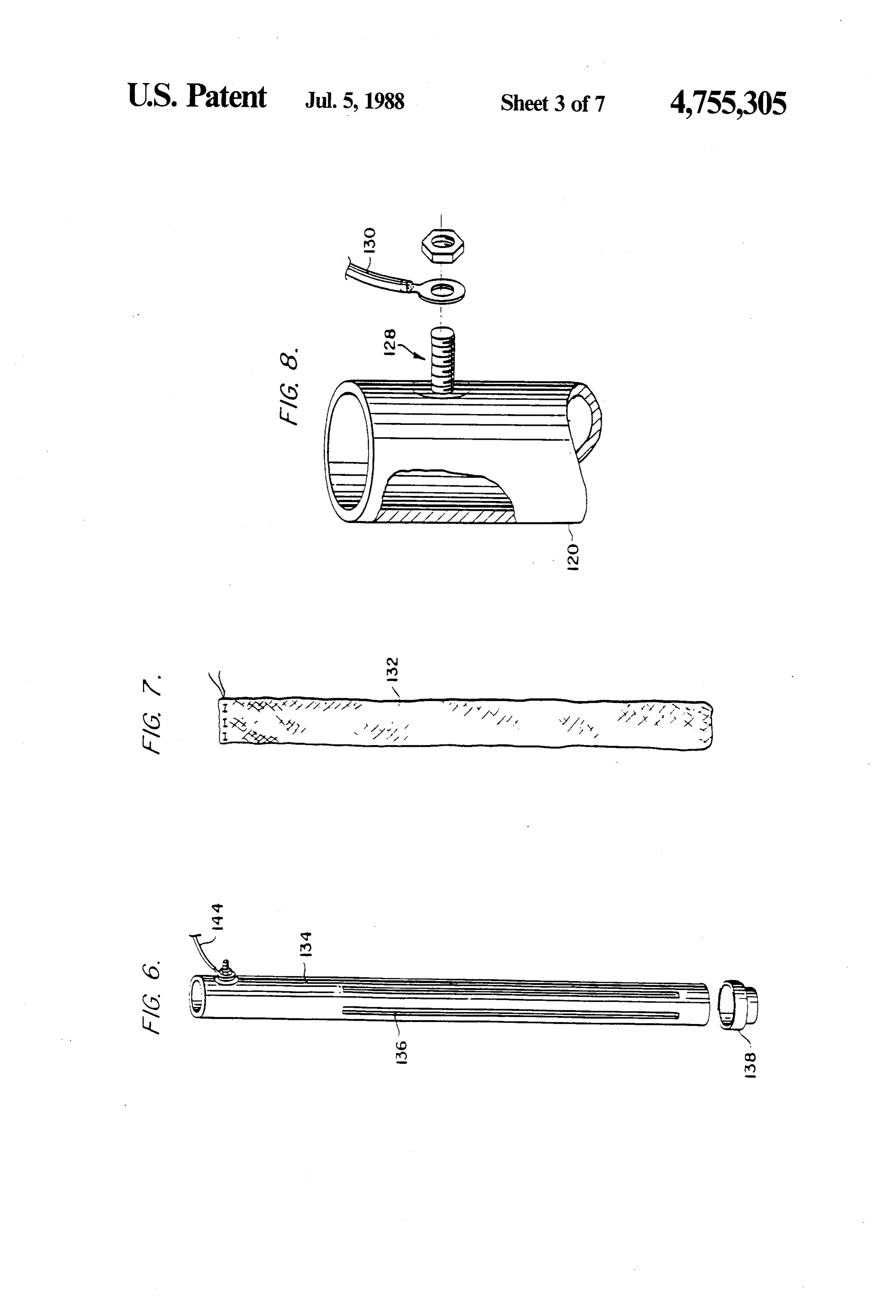
into an open headbox disposed above a moving filter FIG. 6 is a detailed elevational view of one of the belt driven by rollers moving through the electrokinetic cathodes shown in FIG. 5;
dewatering zone. An adjustable dam may be provided FIG. 7 is a detailed description of a filtrate sock that to maintain the sludge level. A vacuum box provides a normally covers a cathode;
vacuum to aid the removal of the permeate which FIG. 8 is a detailed view from FIG. 4 showing the passes through the filter onto a slotted rubber support manner by which electrical connection is made with the belt. A belt washing system and means for extracting electrodes;
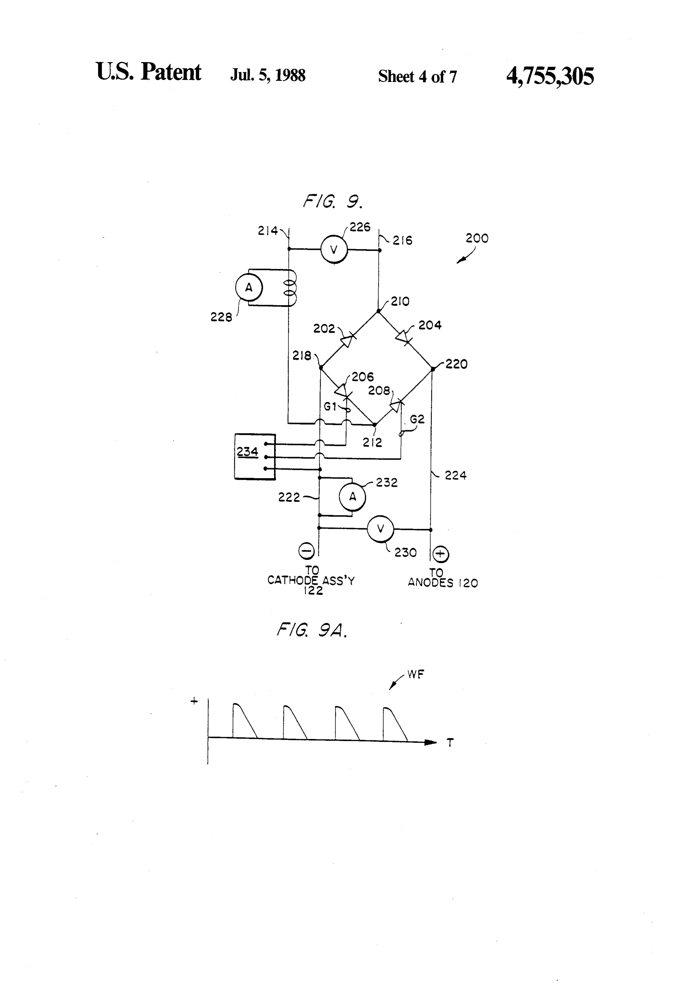
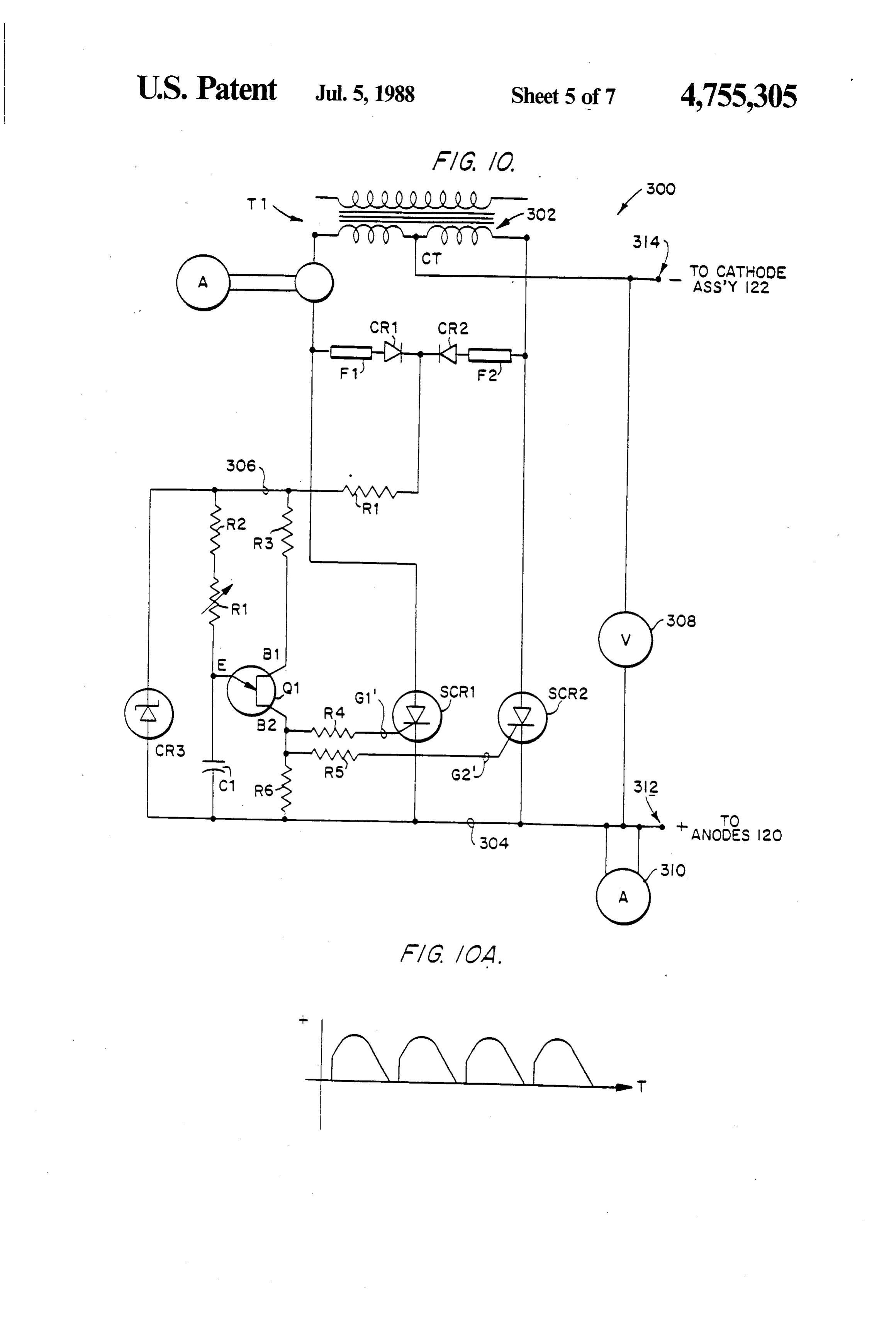
sludge cake at the finishing end of the process may also be provided. Preferably, the anode assembly is provided forFIG. 9 is an electrical schematic diagram of a circuit full wave rectification of alternating current to sup in the interior of an upper filter belt while the cathode O ply an intermittent unidirectional current or "chopped' assembly is provided at the interior of a lower filter belt pulse to the electrode modules of FIG. 1; to define a dewatering zone between them, the elec FIG. 9A is a graphical representation of the profile of trodes being arranged so that an electric field is estab the intermittent unidirectional current or "chopped' lished therebetween to achieve the electrokinetic dewa pulse provided by the circuit of FIG. 9; tering. In the alternative, the cathode can be made a 15 FIG. 10 is an electrical schematic diagram of an alter part of the moving belt. nate electrical circuit for supplying intermittent unidi The method and apparatus provide dewatering and rectional current or "chopped' pulse to the electrode concomitant solids consolidation commensurate with or modules of FIG. 1;
superior to prior methods and apparatus but at substan FIG. 10A is a graphical representation of the inter tially reduced energy consumption rates and accord 20 mittent unidirectional current or "chopped' pulse pro ingly provides a significant economic advantage when vided by the circuitry of FIG. 10;
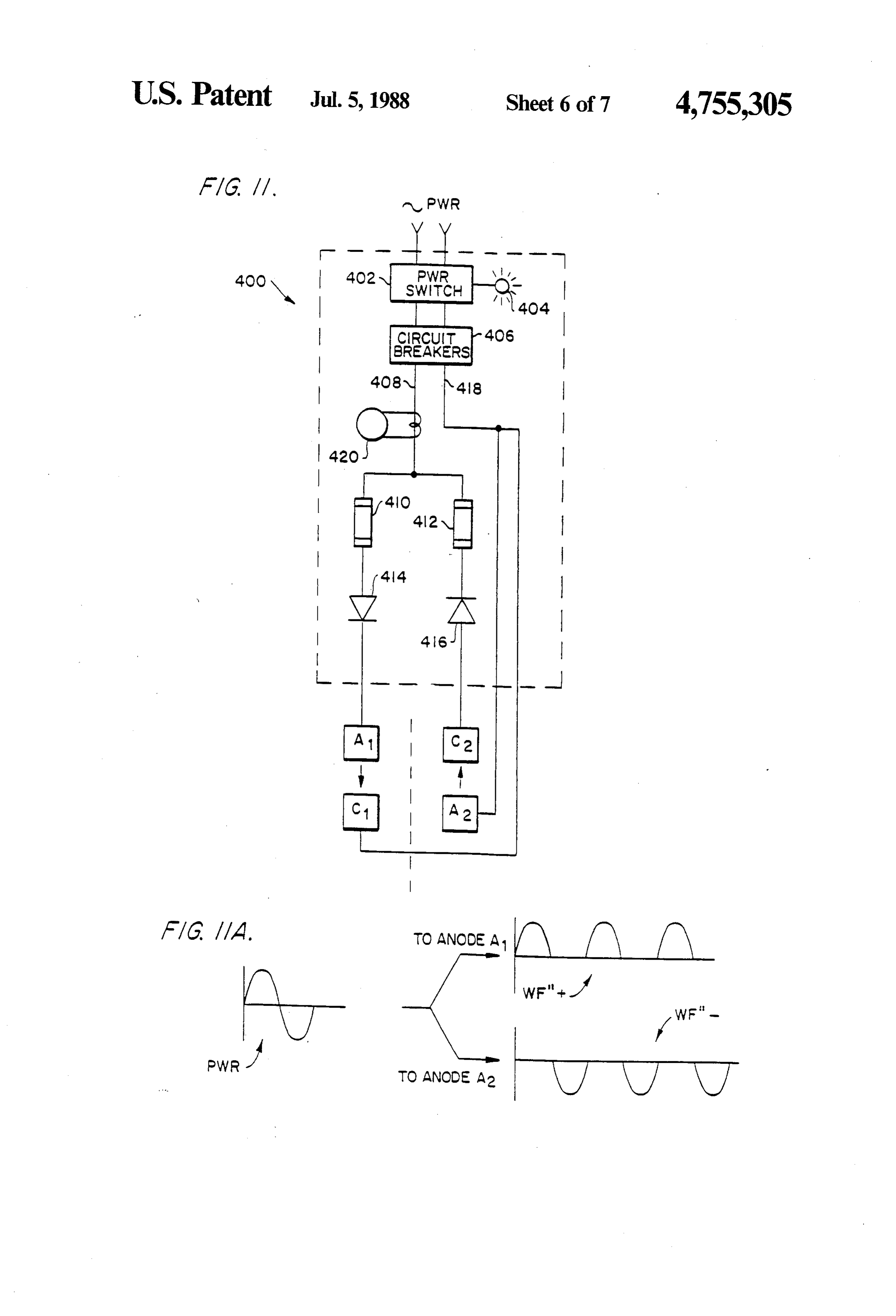
compared to prior systems. FIG. 11 is an electrical schematic diagram of an alter The exact mechanism by which the use of intermit native electrical circuit for supplying one-half wave tent unidirectional current to generate the applied elec rectified alternating current to the electrodes of FIG. 1, tric field effects efficient dewatering is not entirely 25 if the two fields of electrodes can be separated by a known. In prior electrokinetic dewatering arrange large resistance, i.e. distance to prevent cross electric ments, in which DC was used to generate the applied field shorting;
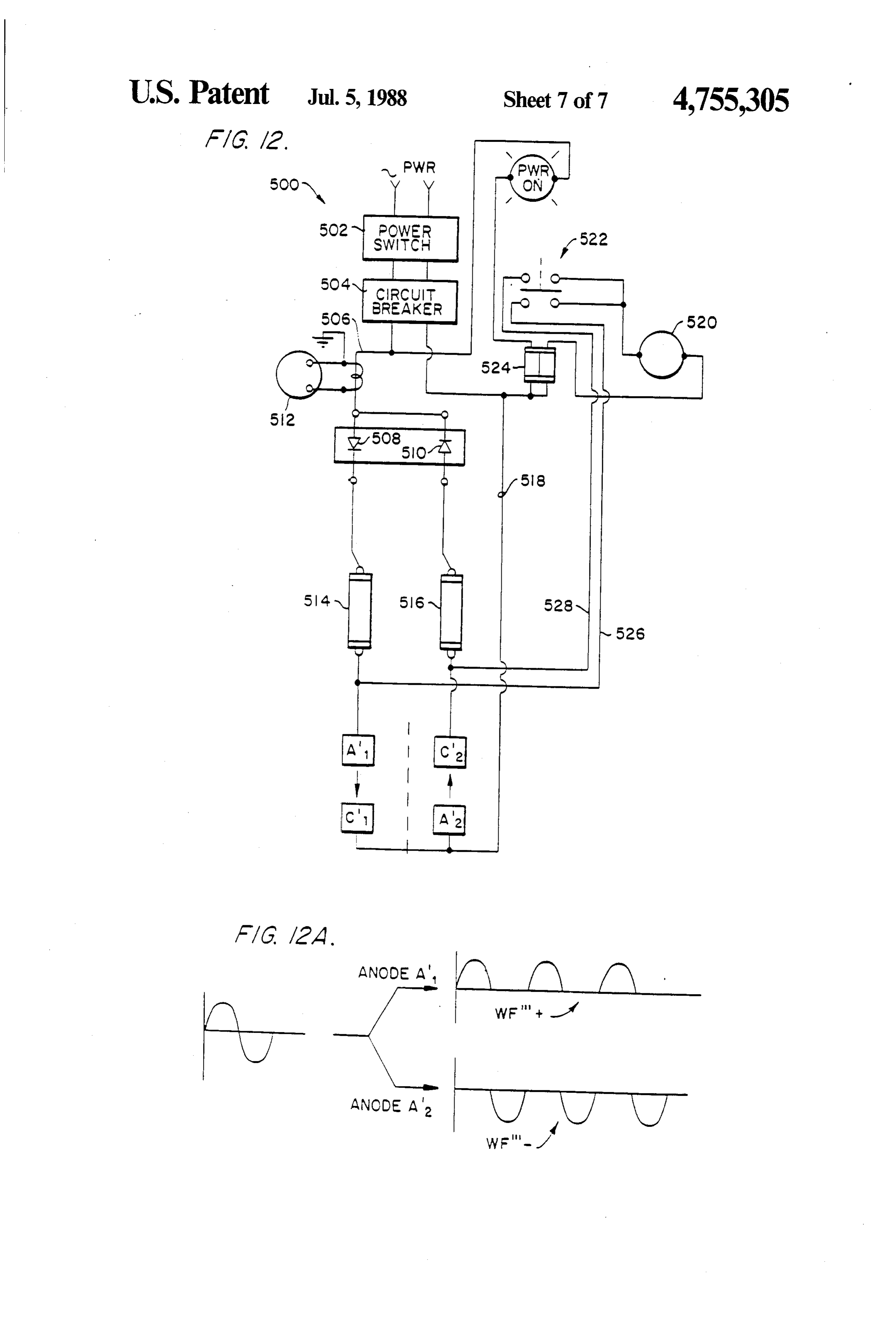
electric field to the sludge, it is possible that the posi FIG. 11A is a graphical representation of the rectified tively and negatively charged particles accumulate in wave form provided by the circuitry of FIG. 11, to zones or regions immediately adjacent to their respec 30 yield an intermittent unidirectional current; tive oppositely charged counter electrodes and form a FIG. 12 is an electrical schematic diagram of an alter "cloud' of similarly charged particles that may repel nate electrical circuit for supplying one-half wave recti additional particles from joining the "cloud' and effec fied alternating current ot the electrode modules of tively screen the electrode from slurry. This effect is FIG. 1, it the modules cannot be separated by a large commonly known as electrode polarization. In the case 35 resistance;
of the present invention, it is believed that the chopped FIG. 12A is a graphic representation of the rectified wave form or intermittent unidirectional current or "chopped' pulse of the applied electrical energy may yieldwave
AC form provided by the circuitry of FIG. 11, to an intermittent unidirectional current;
limit formation of this accumulation of otherwise repel FIG. 13 is a side illustration, drawn partially schemat ling charged particles. In any event, the results ically, of an apparatus for providing continuous electro achieved niques.
have been more cost effective than prior tech kinetic dewatering by continuously conveying sludge through a dewatering zone;
BRIEF DESCRIPTION OF THE DRAWINGS FIG. 14 is a more detailed view of the apparatus of FIG. 13 to illustrate in perspective, the detail of an
The above brief description, as well as further ob 45 apparatus for practicing the continuous electrokinetic jects, features, and advantages, of the present invention dewatering according to the invention and the applica will be more fully appreciated by reference to the fol tion of such techniques to existing sludge conveyors; lowing detailed description of presently preferred but FIG. 15 is a top perspective view of the cathode nonetheless illustrative embodiments when taken in assembly in a rubber support belt for alternative use in conjunction with the accompanying drawings wherein: 50 the apparatus of FIGS. 13 and 14;
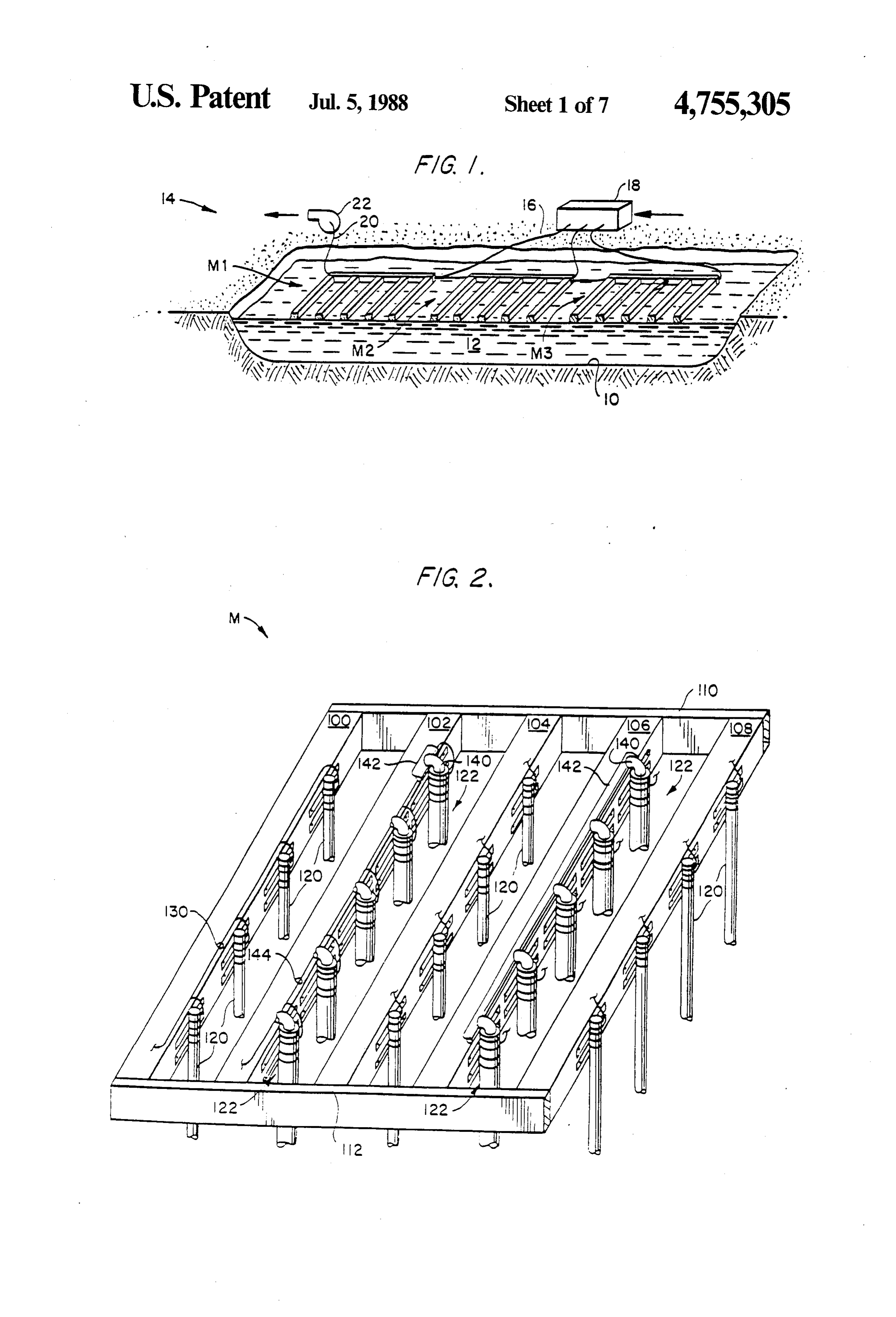
FIG. 1 is a schematic perspective view, in cross sec FIG. 16 is a side perspective view of the moving tion, of an exemplary landfill operation using the appa electrical contact assembly for the cathode of FIG. 15; ratus and method of the present invention to effect FIG. 17 is a circuit diagram similar to FIG. 11 for dewatering of a sludge pond; supplying power to either the batch or continuous sys FIG. 2 is a schematic, perspective view of an elec 55 tems;
trode module for establishing an electric field within the FIG. 18 is a diagram of wave forms taken at various sludge pond shown in FIG. 1; points of FIG. 17; and
FIG. 3 is a partial perspective view of an electrode FIG. 19 is a simplified block diagram of other electro support float used in the module shown in FIGS. 1 and kinetic processes to which the invention may be ap 2; plied, according to the teachings of this second con FIG. 3A is an exploded perspective view of the elec tinuation-in-part application.
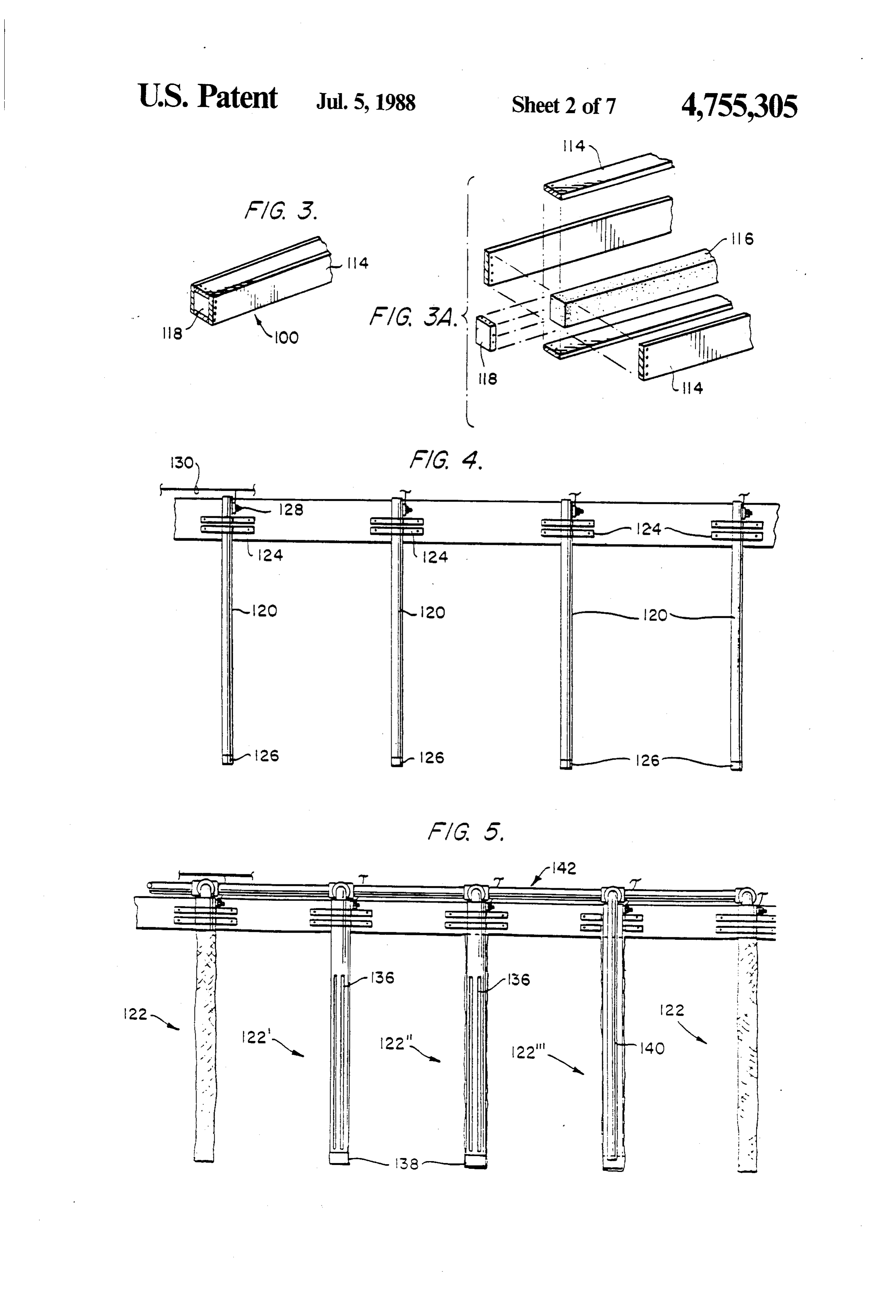
trode support float shown in FIG. 3;
FIG. 4 is a side elevational view of anode support DETAILED DESCRIPTION OF THE float with four anodes secured to and depending from PREFERRED EMBODIMENT the support; 65 The dewatering method and apparatus of the present FIG. 5 is a side elevational view of a cathode support invention may be utilized, as shown in FIG. 1, for dewa float with five cathodes secured to and depending from tering sludge at a landfill site so that the solids within the float; the sludge consolidate and densify sufficiently to sup
Page 12
port a covering layer of earth. As shown in FIG. 1, a pit located at the lower end of each anode 120 to seal the or depression 10 is excavated in the earth and filled to a interior of the anode. As shown in FIG. 8, a threaded selected level with a solids-containing sludge 12 to stud 128 is secured as by welding to the upper end of thereby define a sludge pond 14. In the alternative, the each anode 120 and serves as a terminal for connection pond 14 may be formed without excavation by enclos to a power carrying wire 130. In FIG. 2, only the an ing a selected area with earthen dikes and filling the odes 120 on the electrode support float 100 are shown so-called area with the sludge 14. connected by the conductor 130, it being understood The sludge to be dewatered is typically a fluid-pump that each of the anodes 120 on the two other anode able mixture of water and solids with these solids in electrode supports floats 104 and 108 are likewise inter cluding macro-molecules, colloidal particles, and sus 10 connected by conductors 130 from the three anodes pended particles. These types of sludge are characteris electrode support floats 100, 104, and 108 connected to tically produced by the paper making and related fiber a common anode conductor (not shown) that passes production industries. through the power cable 16 to the power supply 18 Electrode modules M1, M2, and M3 are located in (FIG. 1).
the pond 14 and are designed to float on the sludge 15 As shown in FIG. 2, the cathode assemblies 122 are surface 12 as described more fully below. The modules secured to the electrode support floats 102 and 106 M1, M2, and M3 are spaced a selected distance from intermediate the anode support floats 100, 104, and 108. one another by spacing members (not shown) with the Each cathode assembly 122 is designed to both function total number of modules M required to dewater the as an electrode and as a filtrate removal device. Each pond 14 proportional to the overall surface area of the 20 cathode assembly 122 includes an outer filtration bag or pond. As described more fully below, each electrode sock 132 (see FIG. 7) in the form of a hollow, elongated module M includes a plurality of anodes and cathodes woven fabric tube closed at its lower end and woven (not shown in FIG. 1) that are secured to their respec from, e.g. a polyester or like material or fabricated from tive modules and extend generally vertically down a non-woven material such as Dupont Typar. The sock wardly into the sludge 12. The various anodes and cath 25 132 is drawn up and over a cathode pipe 13 (FIG. 6) odes are connected by respective electrical conductors which, in the preferred embodiment, is a schedule 10 16 to a power source 18 which is designed, as described carbon steel (4" inside diameter) 6' long pipe secured at below, to apply an electrical potential to the anodes and its upper end to its respective electrode support float in the cathodes to establish an electric field between the a manner similar to that for the anodes 120 discussed ... respective oppositely poled electrodes and thus through 30 above. In FIG. 5, an exterior view of a cathode assem the sludge 12. The cathodes are provided with filtering bly 122 with its filtration sock 132 in place on the cath media to remove water from the sludge through a fluid ode pipe 134 is shown on the left and right of the figure, ... conduit 20 that extends along and between each of the a cathode assembly 122 with its filtration sock 132 modules M and conducts filtrate to a water removal shown in cross section is referred to by the reference pump 22 for subsequent discharge or disposal. In time, 35 character 122', and a cathode assembly 122 with both the level of the sludge 12 in the pond will drop as the its filtration sock 132 and cathode pipe 134 shown in - solids concentration increases to the point where the cross section is referred to by the reference character dewatered sludge has substantial load bearing capacity, 122".
- at which time, the modules M1-M3 are removed and As shown in FIG. 5 reference characters 122" and : the solidified sludge 12 covered with a layer of earth to 122") and in FIG. 6, each cathode pipe 134 has prefera , , complete the landfill operation. bly three equally spaced, longitudinally aligned slots ; : An exemplary electrode module M is shown in FIG. 136 formed in the wall of the cathode pipe 134. Prefera 2 and includes five electrode support floats 100, 102, bly, each of the slots 136 terminates adjacent the ends of 104, 106, and 108 that are secured in a spaced parallel the pipe 134 with the lower end of each cathode assem relationship to one another by end plates 110 and 112. In 45 bly being terminated by a suitable pipe cap 138. A coaxi the preferred embodiment, the electrode support floats ally aligned water removal tube 140 (see cathode assem 100-108 and the end plates 110 and 112 are fabricated bly 122" in FIG. 5) extends into the interior of each of from construction-grade wood members with the floats, the cathode assemblies 122 with the lower open end of as shown in detail in FIGS. 3 and 3A, fabricated from each water removal tube 140 positioned adjacent the 1'X8'x16' boards 114 secured together about a styro 50 lower end of the cathode pipe 134. The upper end of foam floation block 116 with end caps 118 provided to each of the water removal tubes 140 is connected to a seal the ends of each of the electrode support floats. The header pipe 142 that runs the length of each cathode end plates 110 and 112 that secure the electrode support assembly electrode support float 102 and 106 with the floats 100-108 together to complete each electrode header pipes 142 communicating with a common mani module M are also preferably 2"x8"x16' boards. Ac 55 fold (not shown), which in turn, connects through the cordingly, each electrode module M has 16'x16' over conduit 20 to the water removal pump 22 (FIG. 1). A all dimensions. suction pressure is established at the inlet of each water The electrode supports 100, 104, 108 serve as sup removal tube 104 by the operation of the pump 22 to ports for the anodes 120 as shown in further detail in remove collected water as described more fully below. FIG. 4, and the intermediate electrode support floats In a manner analogous to the electrical connection 102 and 106 serve as supports for the cathode assemblies shown in FIG. 8 for the anodes 120, each of the cathode 22 as shown in further detail in FIGS. 5-7. pipes 134 also includes a threaded stud 128 secured to its The electrode support floats 100, 104, and 108 each upper end used for effecting connection to a cathode include four equi-spaced anodes 102. In the preferred wire 144. In FIG. 2, only the cathode assemblies 122 on form, each anode 120 is a schedule 40 carbon steel pipe 65 the electrode support float 102 are shown connected by (2' inside diameter) approximately 6' long and secured the conductor 144, it being understood that each of the at its upper end by securing straps 124, brackets, or the cathode assemblies 122 on the other cathode electrode like, to the side of its respective float. An end cap 126 is support float 106 is likewise interconnected by a con
Page 13
ductor 144, with each of the conductors 144 from the The wave form WF' produced at output terminals two cathode electrode support floats 102 and 106 con 312 and 314 of the circuit of FIG. 10 is shown in FIG. nected to a common cathode conductor (not shown) 10A. As shown therein, successive alternations include that passes through the power cable 16 to the power a sharp leading edge with the conduction angle con supply 18 (FIG. 1). trolled by the resistor R1. Depending upon the adjusted Suitable power supply 18 (FIG. 1) circuits for apply valve of the resistor R1, the capacitor C1 charges to a ing a chopped alternating current to the anodes 120 and voltage sufficient to cause the uni-junction transistor Q1 cathode assemblies 122 of the electrode modules M to to switch thereby permitting current flow through the establish an electric field through the sludge 12 are resistors R4 and R5 to effect gating the silicon con shown in FIGS. 9 and 10. In FIG. 9, the power supply 10 trolled rectifiers SCR1 and SCR2. In the preferred circuit 200 includes rectifier diodes 202, 204, 206, and embodiment, Q1 is a 2N2646 transistor, the SCR's are 208 connected in a conventional full wave bridge con G.E. C180E diodes, and the diodes CR1 and SR2 are figuration with main power applied to points 210 and SK3484 diodes, the zener CR3 is an SK 3751 diode, and 212 from power mains 214 and 216 and with output 5 the capacitor C1 has a 0.2 mfd. value.
power removed from points 218 and 220 respectively In operation, the power supply circuits of FIGS. 9-12 along output lines 222 (ground) and 224 (positive), re are used to apply a positive potential to the anodes 120 spectively. A volt meter 226 and an ammeter 228 are and a negative potential to the cathode assemblies 122. connected to the power mains 214 and 216 to monitor When the electrode modules M1-M3 are in position as input power and, likewise, another voltmeter 230 and 20 shown in FIG. 1, an electric field will be generated ammeter 232 are connected to the output lines 222 and through the sludge 12 between the various anodes 120 224 to measure output power applied to the electrode and cathode assemblies 122. As is also known in the art, modules M. solids-containing sludges include macro-molecules, col The diodes 206 and 208 are silicon controlled rectifi loidal particles, and suspended particles that have a net ers (SCR's) with respective gate terminals G1 and G2 of positive or net negative charge. In addition, sludges can the diodes, connected to an SCR triggering circuit 234. 25 contain ions including metallic ions that associate with The triggering circuit 234 operates to control the gating water molecules. In response to the application of the of the silicon controlled rectifiers 206 and 208 to selec applied electric field, positively charged particles will tively gate them at a selected firing angle on each suc andmigrate toward the negative cathode assemblies 122, cessive alternation of the power to provide a wave form 30 will inmigrate a converse manner negative charged particles to the positively charged anodes 120 with
WF shown in FIG.9A. The wave form WF includes a steep leading edge that occurs upon successive trigger the solids densifying. While the respective positive and ing of the SCR diodes 206 and 208 and a conventional negative particles are migrating, the liquid carrier sinusoidal trailing edge. As is conventional in the art, passes through the filter sock 134 of each cathode as the triggering circuit 234 may take the form of a resis 35 pipe 134.122The sembly and through the slots 136 of each cathode liquid carrier, that is, water, collects at tor/capacitor series circuit with the connection be the bottom of the tween the resistor and the capacitor connected to the through the watercathode pipes 134 where it is removed recovery tubes 140 with the neces gates of the SCR's 206 and 208 with the firing angle sary suction provided by the pump 22 (FIG. 1). controlled by control of the resistance value.
Another power supply circuit 300 for also providing ageWith continued operation of the system, the percent solids concentration increases to the point where a chopped alternating current wave form to the elec the solids densify and consolidate to provide a load trode modules is shown in FIG. 10 and includes a trans supporting former T1 having a center tapped secondary 302 with removed from surface. At this point, the modules M may be the center tap CT establishing a ground potential. The ing layer of earth the consolidated sludge 12 and a cover placed over the sludge layer to com terminal ends of the secondary 302 are connected to the 45 plete the landfill operation.
positive output line 304 through silicon controlled recti fiers SCR1 and SCR2. The firing angle of the silicon theAnother electrode power circuit for providing a wave form to modules is shown in FIG. 11 and includes controlled rectifiers SCR1 and SCR2 is controlled a power switch through a firing circuit that includes a uni-junction 404 for connection402to and associated "power on' lamp transistor Q. The emitter of the transistor Q1 is con 50 circuit breaker 406. A power source the power and a protective nected to a series RC circuit that includes an adjustable through fuses 410 connected to the diodeis414 line 408 connected and the resistor R1, a fixed resistor R2, and a capacitor C1 con fuse 412 connected to the cathode of the diode 416. The nected between the positive output line 304 and a bias cathode of the diode 414 is connected to the anodes supply line 306 with the bias supply line held at a con (schematically illustrated as All) of one of the modules stant voltage by the zener diode CR3. The base connec 55 while the anode of the diode 416 is connected to the tions of the uni-junction transistor Q1 are connected cathodes (as schematically illustrated as C2) of another between the positive output line 304 and the bias supply module. The respective counter electrodes, that is, cath line 306through resistors R3 and R6. The base terminal ode C1 and anode A2 are connected through the return B2 of the transistor Q1 is connected through resistors power line 418 to the circuit break 406. An amp meter R4 and R5 to the gate terminals G1 and G2 of the 420 is coupled to the line 408 to measure current flow. silicon controlled rectifiers SCR1 and SCR2, respec Each set of electrodes A-C and A2-C2 establishes an tively. The bias potential on bias supply line 306 is sup electric field therebetween to effect the desired dewa plied through a limited resistor R1 by diodes CR1 and tering. In order to avoid cross-field shorting, it is desir CR2 connected through fuses F1 and F2 to the terminal able that the electrodes that define two fields be sepa ends of the secondary 302. A voltmeter 308 and an 65 rated by an electrically significant distance. ammeter 310 are provided to measure output power In operation, alternating current, as represented in consumed in establishing the dewatering electric field in FIG. 11A, is applied through the fuses 410 and 412 with the sludge 12. the diode 414 passing the positive alternations WF'--
Page 14
and the diode 416 passing the negative alternations would usually be consumed if using direct current in an WF'-. operation of this type.
Another power circuit 500 for providing a wave form EXAMPLE II to the electrode modules is shown in FIG. 12 and in cludes a power switch 502 and circuit breaker 504 5 Four electrode modules were installed in another which provides supply power through a line 506 to sludge pond that contained sludge with an average diodes 408 and 510 with an amp meter 512 coupled to concentration of 4-7%. The system operated for 40 the line 506 between the circuit breaker 504 and the days with the solids concentration at a 3 foot depth diode 508 to effect current measurement. The cathode increasing from 4-7% to 25% despite 7" of rainfall and of the diode 508 is connected through a fuse 514 to the 10 continued sion.
lime spraying operations for odor-suppres
Approximately 143,000-150,000 gallons of filtrate anodes of a first electrode module as indicated at A' were removed from the site which had an effective while the anode of the diode 510 is connected through electrical field area of about 4200 ft2. At the completion a fuse 516 to the cathodes of another electrode module of the trial, as indicated by C2. The respective counter electrodes, 15 mately 25-27% solids at the depth of 3 feet were approxi that is, cathodes C1 and A2 are connected through a approximately 90%. with wave form switching occurring at common return line 518 to the circuit breaker 504. A bidirectionally responsive volt meter 520 is connected using Experience indicates that comparable dewatering through a double-pole double-throw switch arrange electrical direct current consumes about four times as much ment 522 and fuses 524 to the return line 518 and the 20 power in kilowatt hours than was consumed in Examples electrodes A' C'2 through lines 526 and 528, respec which this improved I and II above. The exact mechanism by dewatering efficiency is achieved tively. When the switch 522 is in a first position, the volt using intermittent unidirectional meter 520 is connected to the electrode set A1-C1 to pulses is not known but, as discussed current or "chopped' measure the applied electric voltage potential, and, related to the lack of formation of a zone above, it may be of accumu when the switch 522 is in a second position, the volt 25 lated charged particles adjacent the electrodes, which meter 520 is connected to the electrode set A'2-C'2 to zone would normally screen the electrodes from the measure the voltage potential across the latter electrode sludge and limit their efficacy. Set. While the invention has been described in terms of a The circuit of FIG. 12 operates in a manner similar to landfill environment, it is suitable for use in fixed-site that of FIG. 11 in that alternating current wave form, as 30 operations in which sludge is dewatered on a batch basis shown in FIG. 12A is presented to the diodes 508 and in a fixed container with the solidified sludge being 510 with the diode 508 passing positive alternations thereafter removed from the container to permit treat WF"-- to the electrode set A'1-C1 and the diode 510 ment of another batch, and as will described in connec ... passing negative alternations WF'- to the electrode tion with FIGS. 13-18, in a continuous dewatering set A'2-C2. 35 process.
In the case of the electrode modules of FIG. 11, the In practicing the invention, it has been found desir field direction for the electrodes A1-C1 is opposite that able to cut the slots 136 in the cathode pipe 134 rela for the electrodes A2-C2 and, as similarly shown in tively high and near the top of the cathode pipe to FIG. 12, the field orientation for the electrodes A'i-C" permit withdrawal of surface water from the pond. The is opposite that for the electrodes A2-C2. Since the surface water may result from either a natural settling of adjacent fields are oppositely oriented in the two fig solids toward the bottom of the pond, leaving water ... ures, it is desirable that the fields established by the near the top or from rainfall. In either instance, this electrode sets be sufficiently separated to prevent cross practice permits the vacuum pumping system to draw field current leakage or shorting. This separation is water from the pond at faster rate and expedites the schematically represented in FIGS. 11 and 12 by the 45 densification of solids in the pond. In addition, it has vertical broken line between the electrode sets. been found preferable to use a filter sock having a single The efficacy of the above-described system may be layer rather than one made from multiple layers. appreciated by considerations of the following two Experience thus far with practicing the invention also examples: indicates that controlling the voltage drop and the cur 50 rent density between the respective anode and cathode
EXAMPLE I
electrodes to within certain ranges enhances the results
The electrode modules were installed in a sludge obtained. Presently, it is believed that the voltage drop pond that contained sludge with an average concentra is preferably within a range of about 0.1 to about 0.7 tion of approximately 9% solids. The sludge had an volts per centimeter, while the current density should initial conductivity of 103 micromhos per centimeter 55 be in a range of about 300 to about 800 micro-amperes with the conductivity increased by a factor of six be per square centimeter and, preferably, at about 750 cause of the addition of lime to the surface of the sludge micro-amperes per square centimeter. In addition, it is for odor control. The system operated over a period of presently preferred that the pH of the sludge be in the 40 days with the average solids level measured at a range of about 6.5 to about 7.5, although the process has depth of 3 feet increasing from 9% to 27% with a de 60 been applied successfully to substrates over the pH crease in pond level of about 22" and 24". During this range 2.0 to 12.0.
period, approximately 75,000-86,000 gallons of water The application of the techniques of the invention filtrate were removed with the water having a solids described in connection with FIGS. 1-12 to a continu concentration of approximately 500 ppm. The total ous dewatering process is described in connection with power consumed during the dewatering operation was 65 FIGS. 13-18hereinafter. An apparatus for continuously 3100 kilowatt hours with each wave form switched at dewatering sludge is known and described in U.S. Pat. an approximately 90 phase angle. The power con No. 4,244,804, which is herein incorporated by refer sumed is approximately one-fourth of the power that ence. The structure of that patent is thus similar to the
Page 15
structure of FIG. 13, to which the principles of this In the apparatus of FIG. 14, an adjustable dam 635 invention are applied to effect dewatering on a continu (shown in expanded detail in FIG. 14B) is applied at the ing basis. inlet to control the egress of the sludge and to obtain In FIG. 13, an apparatus designated generally by the some measure of initial draining of liquids from the reference numeral 601 is depicted, partially in schematic sludge fed by gravity at the feed pipe 637. In this re form, for continuously dewatering sludges in the man spect, as shown by the detail in FIG. 14A, the headbox ner according to the invention heretofore disclosed in a section 639 is divided into a formation zone 641, a drain rapid, cost-effective manner, in situ, to ease the burden of sludge handling and disposal or material reclamation. ing zone 643, and a drying zone 645, in that order, ac cording to the direction of belt travel, indicated by the
In FIG. 13, the sludge 603 is fed continuously from the 10 arrow 647 in FIG. 14A.
discharge of the process which produces it (not shown) The apparatus is disposed on a structural frame desig into the open top of a headbox 605. The apparatus in nated generally by the reference numeral 649, the de cludes a continuous upper filter belt 607 driven by a tails of which are not essential to the practice of the driving roller 609 and an idler roller 611. The anode 613 invention, and which may vary from installation to is disposed intermediate the rollers 609 and 611 and 15 installation, particularly if the apparatus is retrofitted to between the upper and lower webs of the filter belt 607. an existing sludge removal system. As shown in the A lower filter belt 615 is similarly disposed about a detail of FIG. 14C, the filter of the belt 653 includes a driven roller 617 and an idler roller 619. A motor 621 is filter medium 651 on which is disposed the caked or connected to a gear box 623 for controlling the rate of caking sludge 655 disposed over a slotted drainage belt speed of the lower filter belt. The upper filter belt 607 is 20 653 supported by a guide member 656. A vacuum sys disposed relative to the lower belt 615 so that the open tem shown generally the reference numeral 657 and in ing at the inlet portion of the process (i.e. the space detail in FIG. 14D aids the removal of the permeate between the in-register portions of the belts 607 and which passes through the filter 651 onto the support 615) is slightly greater than that at the exit portion of the belt 653, which is preferably made of rubber. The sup process because of the compaction of the sludges as a 25 port belt, as mentioned, is slotted in order to remove the result of the process according to the invention. The permeate and distribute the vacuum across the under sludge is discharged from the lower end of the headbox side of the filter fabric 651. While the apparatus of FIG. 605 onto the forward end of the lower filter belt 615 and 14 is shown as a Straight Line Filter system, it can be is carried thereon into the electrokinetic dewatering used as the basis for the twin belt continuous system zone defined, according to the invention heretofore 30 shown in FIG. 13 by the addition of the upper filter belt, described, between the anode 613 and cathode 625. as shown in FIG. 12, with conventional structural mod Charged particles within the sludge, including macro ifications of the frame 649. In this manner, it can be seen molecules, colloids, and suspended particles, electro that a conventional Straight Line process can be readily phoretically migrate to the oppositely charged counter adapted and thus retrofitted to the continuous dewater electrode and consolidate, in the continuous process of 35 ing apparatus of the invention. Such modification in FIG. 13, according to the same principles discussed in cludes a supportunit for the rear of the added upper belt connection with FIGS. 1-12 above. to provide adjustable supports to permit the front and Filtration media, shown generally by the reference rear ends of the upper belt assembly to be raised and numeral 627, are located at the cathode 625 to permit lowered independently to achieve the desired operating the electro-osmotic removal of water from the sludge to 40 ranges.
encourage the dewatering of solids and densification of FIG. 14E shows a filter washing system 661 for the sludge. The electrical energy applied to the elec washing the filter fabric 651 by using a top washing trodes is a chopped, time-varying, intermittent, unidi spray device 663 and a bottom washing spray device rectional current, of the type heretofore described in 665. The remaining details of FIG. 14, such as tension FIGS. 9-12, or hereinafter described in FIG. 17, having 45 ing adjustments, idler rolls, and the like, are conven a rapid rise edge which provides dewatering results tional and thus known to one of ordinary skill in this art. comparable to prior methods which use direct current The anode assembly (see FIG. 13) includes insulating or full AC current but at substantially reduced energy support members for supporting an anode section elec consumption to provide more economical dewatering. trically connected, such as by graphite bars mounted in The dry sludge is discharged as a sludge cake 631 SO slots cut into the insulating supports and fastened by from the discharge end 632 of the process. electrical connectors to carry power from a bus bar It is an additional advantage of the apparatus shown attached to the power unit in a conventional manner. generally in FIG. 13 that it can be retrofitted on existing The cathode assembly (FIG. 13) for the continuous and conventional single belt or twin belt processes for embodiment may alternatively include a plurality of transferring sludge in conventional sludge removal pro 55 conductive rods 675, such as aluminum mounted in cesses. In such a retrofit of the foregoing technology, a transverse slots on the top of the rubber support belt 653 particularized specification for a specific installation can beneath the lower filter fabric 651 as shown in FIG. 14. be developed taking into account the rate at which The rods are mounted to protrude slightly from the side commercial sludges are processed in the presses of exist of the rubber belt, leaving a portion of each rod pro ing processes and the rate at which secondary sludge truding from the belt and embedded in the rubber belt alone would be processed as an independent waste sufficiently to fix the rods firmly in place. Such a struc Stream. ture thus provides a porous cathode plate which allows FIG. 14 shows a perspective view pilot unit for the water to be transported electrokinetically to the rubber application of the process described more generally in belt with minimal interference for removal from the belt FIG. 13 for operating the process at a belt speed in the 65 through the vacuum and filtration collection systems as range of 1 to 18 feet per minute, at a vacuum of 0 to 10 previously described.
inches of water, with a slit height at the inlet of 1 to 6 Because the process is continuous, a moving electri inches and a slit height at the outlet of 0 to 2 inches. cal contact assembly for the cathode, designated gener
Page 16
ally by the reference numeral 677 is shown in FIG. 16 cause charged matter within the liquid to migrate to and includes a stainless steel brush 679 which makes respective oppositely charged electrodes and continu contact with the protruding rods 653 as they enter the ing the process to complete the electrokinetic treatment dewatering zone. The fine wire bristles of the stainless is expected to achieve the advantages of the invention steel brush 679 make an excellent conductor for receiv with a minimized consumption of power in carrying out ing electrical currents applied thereto by a conductor other processes which heretofore may have used or (not shown) connected to the power supply system of required pulsed or intermittent direct current. FIGS. 9-12 or FIG. 17. As is known, electrokinetic phenomena are associ FIG. 17 is a circuit diagram suitable for supplying ated with the movement of charged particles through a power in the form of an intermittant unidirectional 10 continuous medium or with the movement of a continu current pulse 1UCP to the anode and cathode of either ous medium over charged surfaces. The four principal the batch process of the continuous process to establish electrokinetic phenomena are electrophoresis, electro an electric field through the sludge to be dewatered. osmosis, streaming potential, and sedimentation poten The SCR circuit 200 is like that shown and discussed in tial or Dorn effect, which phenomena are related to one detail in connection with FIG. 9, while the uni-junction 15 another through the zeta potential of the electrical dou circuit is like that shown and discussed in connection ble layer which exists in the neighborhood of the with FIG. 10. Therefore, like reference designations charged surface. As was explained, the distribution of have been used to refer to like elements. In this embodi electrolyte ions in the neighborhood of a negatively ment, however, a transformer T1" has its secondary charged surface and the variation of the potential with fully connected to a full wave bridge rectifier 701 and 20 its primary connected to a source of AC power. Fuses distance has been studied. Thus, among electrokinetic processes, these generalized types to which the inven
F1 and F2 are provided between the secondary of the tion may be implied includes electrodialysis processes, transformer T1' and the opposed legs of the input to the which includes electrolysis with membrane processes or bridge rectifier 701.
The bridge 701 includes four diodes CR1'-CR4' ar 25 bipolarCSS.
membrane processes, desalinization and metath ranged to provide full wave rectification of the AC(ac) Electrolysis relates more generally to a method by input signal TP, as shown by the wave form TP2 in which
FIG. 18, taken at the output of the bridge. The firing of lytes orreactions in molten are carried out in solutions of electro salts by the use of electricity wherein the uni-junction transistor Q1 is shown by the wave one or several reactions occur at each electrode when ... form TP3 in FIG. 18 taken at the test point TP3 in FIG. current flows through the cell. For example, sodium is
... 17. As described in connection with FIGS. 9 and 11, produced at the cathode by reduction and chlorine at whichever of the SCR's 206 and 208 has a positive the anode by oxidation in the electrolysis of molten anode voltage at the time of the gating pulse TP3 occurs sodium chloride. Other chemicals such as hydrogen, will fire to apply a voltage to the load for the remainder oxygen, hydrogen peroxide, chlorine, and sodium hy of that half cycle. The firing angle can thus be adjusted 35 droxide are produced by electrolysis and water is en by the variable resistor R1 and capacitor C1 to vary riched in deuterium oxide by electrolysis. Certain met from about 10 to about 180' or fully off. als such as aluminum, magnesium, and sodium are pro The wave form applied to the anode in the dewater ing zone is shown by TP4 in FIG. 18. Fuses F3-F6 are duced by electrolysis of molten salt while fluorine is interposed between the output of the power bridge 200 produced by oxidation of fluoride ions, and anhydrous hydrofluoric acid wherein electrolysis of the aquaeous and the anodes through variable resistors R8-R11 to solution of fluoride produces oxygen because this reac control the current flow at each anode.
Thus, an application of the techniques of the inven tion occurs at lower anodic potentials than fluorine tion to a continuous dewatering system is shown in evolution. The electrolysis of water to form hydrogen and oxy FIGS. 13-18. 45
FIG. 19 is a simplified block diagram of other electro gen is sometimes considered to be the simplest process kinetic processes to which the invention may be applied for aqueous electrolytes. In addition, electrolytic pro as set forth in the suggestions of this second continua cesses are used in metallurgical applications for plating tion-in-part application. In particular, the application or such metals as copper, cadmium, chromium, cobalt, any of the circuits shown in FIGS. 9, 10, 11, 12 or 17 50 gold, iron, lead, nickel, the platinium metals, silver, tin, with the wave forms of FIGS. 9A, 10A, 11A, 12 or 18 and zinc, and alloys such as brass.
in the other electrokinetic processes depicted in FIG. 19 Electrolysis processes are also known which use ion is expected to produce advantageous results as gener permeable membranes or diaphragms which mem ally described in connection with electrophoretic dewa branes may be cation permeable or anion permeable, as tering. 55 well as bipolar. Desalinization, or the purification of sea In the first instance, the method for electrokinetically water to recover salt, is an example of a process using an treating a liquid is not confined to the dewatering of ion permeable membrane cell. Non-aqueous solutes may sludges, slurries or the like, but may be applied for also be used with electrolysis as well as fused salts. And, electrokinetically treating a liquid from a group consist a typical example of metathesis is the reaction ing of emulsions, slurries, and solutions to achieve the 60 CAOH2--2NACL=CACL2-2NAOH.
advantages of the invention, namely to minimize elec The application of such a wave form to achieve the trode polarization and thereby maximize effective use of advantages of the invention is also expected to produce the applied power. The application of a time-varying, advantageous results in connection with the process of intermittent, unidirectional electrical current to a cath electrowinning, or electro-extraction. As is known, ode and anode electrode within the liquid to be treated 65 electrowinning or electro-extraction is the recovery of a to establish an electrical field therebetween within the metal from a solution of its salts by passing an electric liquid wherein the electrical current wave form in current through the solution and is a common process cludes a switching edge at a selected phase angle to for extracting metal from its ore.
Page 17
Thirdly, the application of the techniques heretofore continuing the process to complete the electrokinetic disclosed is also expected to be applicable to electro treatment with a minimized consumption of power phoretic processes other than dewatering sludges and 0.02 to 0.041 kw hrs/gallon of liquid separated out. slurries and the like, such as the electrophoretic pro 2. The method as set forth in claim 1 wherein said first cesses employed in the manufacture of polyvinyl ace 5 mentioned group member is derived from an electrodi tate and polyvinyl chloride. alysis process.
As can be appreciated by those skilled in the art, 3. The method as set forth in claim 1 wherein said first various changes and modifications can be made to the mentioned group member is derived from an electroly described embodiment of the present invention without O sis process.
departing from the spirit or scope of the invention as 4. The method as set forth in claim 1 wherein said first defined in the appended claims and their legal equiva mentioned group member is derived from an electroly lents. sis process characterized as a membrane process. What is claimed is: 5. The method set forth in claim 1 wherein said first 1. A method for electrokinetically treating a member 5 mentioned group member is derived from an electroly selected from the group consisting of emulsions, slur CCSS. sis process characterized as a bipolar membrane pro ries, and solutions for separating liquid from solids and 6. The method as set forth in claim 1 wherein said first so as to minimize and make effective use of the applied mentioned group member is derived from a desaliniza power comprising the steps of: tion process.
placing cathode and anode electrodes within the liq 20 7. The method as set forth in claim 1 wherein said first uid to be treated; mentioned group member is derived from a metathesis applying a time-varying, intermittent, unidirectional process.
electrical current of 60 to 120 pulses/second to the 8. The process as set forth in claim 1, wherein said cathode and anode electrodes to establish an elec first mentioned group member is derived from an elec tric field of 0.1 to 0.7 volts/cm at a current density 25 trowinning process.
of 300 to 800 microamps/cm2 of anode surface 9. A method according to claim 1, wherein said se therebetween in said group member, the electrical lected phase angle is between 10 and 180'. current having a wave form which includes a 10. A method according to claim 1, wherein said switching edge at a selected phase angle of be selected phase angle is 90.
tween 0' and 180' to cause charged matter within 30 11. A method according to claim 1, wherein the cur the liquid to migrate to respectively oppositely rent density is about 750 microamperes.
charged electrodes; and k is k k
Provenance
- Collection
- Cited prior art
- Original PDF
- patentimages.storage.googleapis.com →
- Filed
- 1986-04-11
- Pages
- 17
- Method
- pdftotext (the PDF's own text layer) + pdftoppm 300dpi page scans
- Source
- Google Patents bibliographic record
- Granted
- 1988-07-05
- Inventors
- Henry A. Fremont; William C. Dorman; Champion International Corp
- Transcribed from
- patentimages.storage.googleapis.com →