patent · US4753718
Hydrogen peroxide electrolytic cell
28 June 1988
Page 1 — bibliographic record
United States Patent (19) 11) Patent Number: 4,753,718 Chiang (45) Date of Patent: Jun. 28, 1988 (54) HYDROGEN PEROXIDE ELECTROLYTIC 4,430,176 2/1984 Davison ................................ 204/84 CELL 4,431,494 2/1984 McIntyre et al...................... 204/83
75) Inventor: John S. C. Chiang, Mercerville, N.J. 4,457,953 7/1984 McIntyre et al.................... 427/1.13 73 Assignee: FMC Corporation, Philadelphia, Pa. 4,481,303 11/1984 McIntyre et al...... ... 502/159 4,511,441 4/1985 McIntyre et al...... ... 204/98 (21) Appl. No.: 932,836 4,534,845 8/1985 McIntyre et al. ..... ... 204/265 X 22 Filed: Nov. 20, 1986 4,657,651 4/1987 Wainerdi ............................. 204/265
OTHER PUBLICATIONS
C25B 11/12 Haggin, J., "Trickle-Bed Electrolytic Cell for Peroxide 52 U.S. Cl. .................................... 204/265; 204/266; Developed', C&EN, 3/12/84, p. 16. 204/294; 204/283; 204/284 Oloman et al., "Hydrogen Peroxide Production in 58 Field of Search ............... 204/256, 258, 265, 266, Trickle Bed Electrochemical Reactors, J. of App. Elec
(56) References Cited Primary Examiner-Donald R. Valentine
3,379,626 4/1968 Heuse et al. .................... 204/266 X Andersen; Eugene G. Seems 3,454,477 7/1969 Grangaard ............................ 204/84 57 ABSTRACT
3,462,351 8/1969 Grangaard ............................ 204/83 The invention is an electrochemical cell which is useful 3,506,560 4/1970 Grangaard .. ... 204/263 to reduce oxygen to hydrogen peroxide at a cathode. 3,507,769 4/1970 Grangaard. ... 204/265 The cell avoids the safety hazard of a hydrogen explo 3,591,470 7/1971 Grangaard ............................ 204/84 sion of the prior art cells. The cell has an added advan 3,592,749 7/1971 Grangaard ............................ 204/84 tage in that the dimensions of the cathode are not lim 3,968,273 7/1976 Kastening et al... ... 204/265 X ited by hydrostatic pressures or by the capacity of the 3,969,201 7/1976 Oloman et al. ....................... 204/83 4,118,305 10/1978 Oloman et al. . ... 204/265 channels and pores of the cathode.
4,406,758 9/1983 McIntyre et al...................... 204/98 6 Claims, 2 Drawing Sheets
NSNS
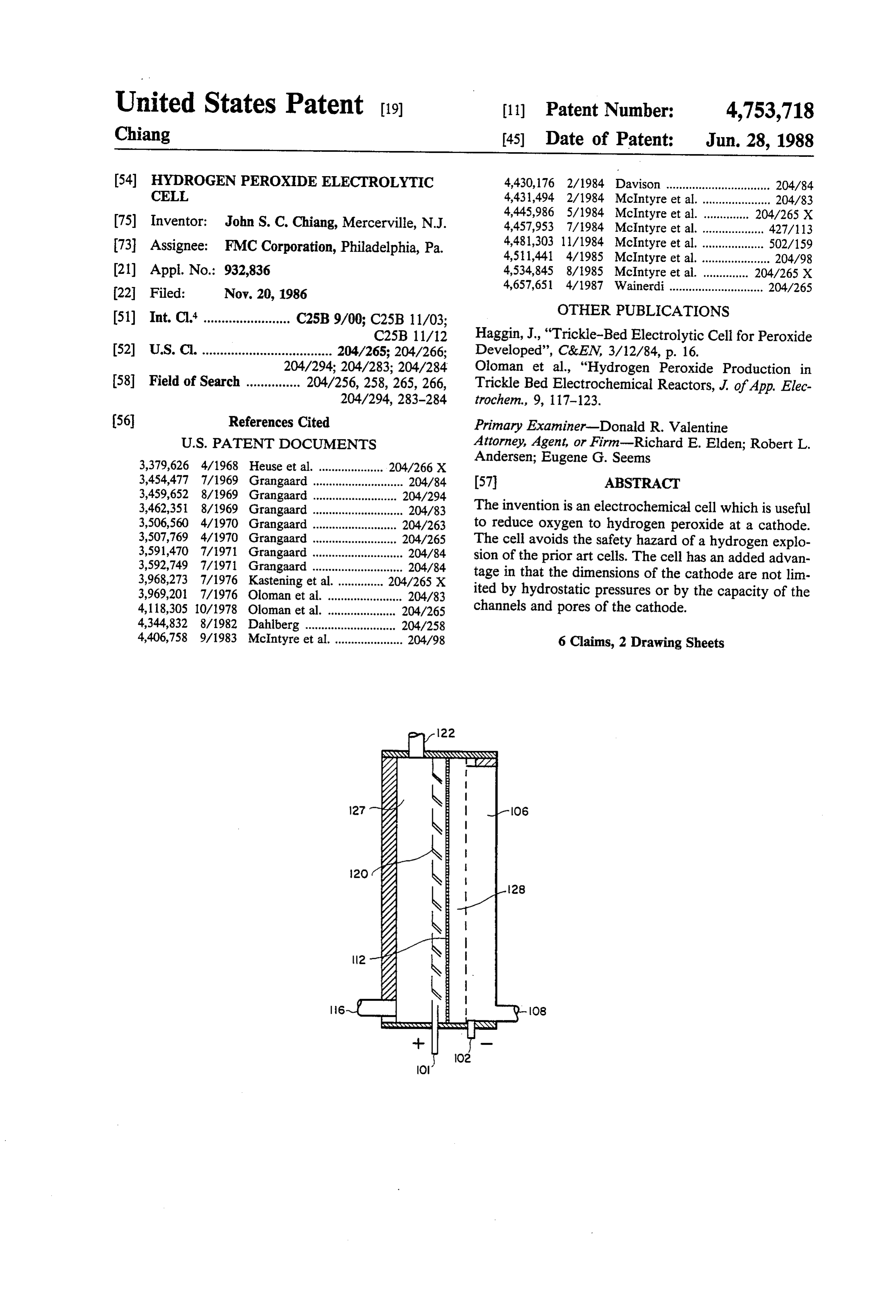
Page 2
Drawing sheet — no readable text.
Page 3
Drawing sheet — no readable text.
Page 4
because the supply of oxygen is inadequate. In the ab
HYDROGEN PEROXIDE ELECTROLYTIC CELL sence of oxygen at the cathode hydrogen gas will be formed. The hydrogen gas may form an explosive mix
The present invention is an electrochemical cell suit able for safely reducing oxygen to hydrogen peroxide at ture the with oxygen gas in the oxygen supply manifold. In alternative, if insufficient oxygen were introduced a cathode in the presence of an alkaline electrolyte. into the cathode, hydrogen would be formed in the For over a hundred years it has been known that oxygen-depleted section which would mix with oxygen oxygen can be reduced at a cathode to form hydrogen peroxide. In spite of the very low voltage for the half in the oxygen-rich Zone to form an explosive mixture. cell reaction the process has never been commercial 10 In U.S. Pat. Nos. 3,454,477; 3,459,652; 3,462,351; ized. 3,506,560; 3,507,769; 3,591,470, and 3,592,749 to Grang U.S. Pat. Nos. 4,406,758 and 4,511,441 teach a aard, the cathode is a porous plate with the electrolyte method for operating an electrochemical cell employ and oxygen delivered from opposite sides for reaction ing a gas cathode. The electrolyte is introduced into the on the cathode. The porous gas diffusion electrode cell in the anode compartment where a gas such as 15 requires a wax coating to fix the reaction zone and oxygen or chlorine is formed. The electrolyte then careful balancing of oxygen and electrolyte pressure to passes through a separating means into a "trickle bed' keep the reaction zone near the surface of the porous or self-draining cathode. Oxygen gas is also introduced plate.
into the cathode and is reduced to form hydrogen per The electrolytic cells of U.S. Pat. Nos. 4,406,758 and oxide. The hydrogen peroxide can optionally be decom 20 4,511,441 have a problem in that vertical dimension of posed or collected and employed as a bleach solution. the cell cannot be varied over a large range because of Both of these patents teach that the desired electro the need to balance the hydraulic pressure differences lytic reaction with gas will take place only where there across the separating means and the need to avoid flood is a three-phase contact between a gas, an electrolyte ing the cathode with electrolyte, an uncontrolled flow solution and a solid electrical conductor. The patents 25 of liquid through the separator is considered to be unde teach that it is necessary to balance the hydraulic pres sirable.
sure of the electrolyte on the anode side of the separat ing means and on the cathode side of the separating ingThe present invention is an electrolytic cell for reduc means to maintain a controlled flow of electrolyte into presence of anto aqueous oxygen hydrogen peroxide at a cathode in the alkaline electrolyte comprising a the cathode and to maintain oxygen gas throughout the 30 cell having an electrolyte cathode. Pores of a sufficient size and number are pro cathode with a first surfaceinlet, a porous, self-draining contacting electrolyte and a vided in the cathode to allow both gas and liquid to second surface forming an exterior surface of the cell, flow simultaneously through the cathode.
The presence of oxygen is required at an oxygen an electrolyte outlet disposed to receive electrolyte cathode not only to maintain a high efficiency, but also draining from the cathode, an anode, separating means to avoid a disastrous explosion. In the presence of an 35 between the cathode and the anode. The separating alkali metal hydroxide the oxygen cathode overall reac means is substantially permeable to the electrolyte and tion is the reaction of oxygen and water to form hy defines an anode compartment containing the electro droxyl ions and perhydroxyl ions (anions of hydrogen lyte inlet and a cathode compartment. The second sur peroxide, a very weak acid). The cathode reaction is 40 face of the cathode is in contact with an oxygen-con 2O2+2H2O-4e-2HO2 +2OH (1) taining gas, and means are provided to controllably and the anode reaction is urge the electrolyte from the electrolyte inlet through the separating means and into the self-draining cathode at a rate about equal to the drainage rate of the electro 45 lyte from the cathode and in a quantity sufficient to fill with an overall reaction of only a portion of the pores of the cathode and having means to exhaust a gas in the anode compartment out of
O2-2OH-2HO2. (3) the electrolytic cell.
When the electrolytic cell is disposed so that the
In the absence of oxygen at the cathode that half cell 50 cathode is generally vertical it is desirable for the cell to reaction is contain means to divert oxygen gas generated at the anode in the anode compartment electrolyte away from the separating means to prevent increasing the ohmic resistance of the cell.
Undesirable side reactions can also take place at the 55 In a particularly desirable embodiment of the present cathode invention, the cell is disposed so that the cathode is maintained in a generally horizontal position. If the anode is disposed in the cell in a position superior to the and at the anode cathode the anode may desirably provide holes or pores as means to divert the buoyant oxygen gas in the elec
HO2 +OH-O2+ H2O+2e. (6) trolyte in the anode compartment away from the sepa rating means. Desirable means to divert oxygen gas can
Consequently, it is important to avoid a local high con include not only louvres in the anode, but also channels centration of the perhydroxyl ion (HO2) from accu in the anode leading the bubbles up and to either side or mulating in the catholyte. 65 both sides, for example, in a "herring bone' pattern. Equation (4) can predominate if the cathode does not Equally effective are mechanical wipers or "paddle contain oxygen gas or hydrogen peroxide (equation 5) wheels' which can be driven by the rising bubbles to either because the cell is flooded with electrolyte, or both sweep the other bubbles from the area and sweep
Page 5
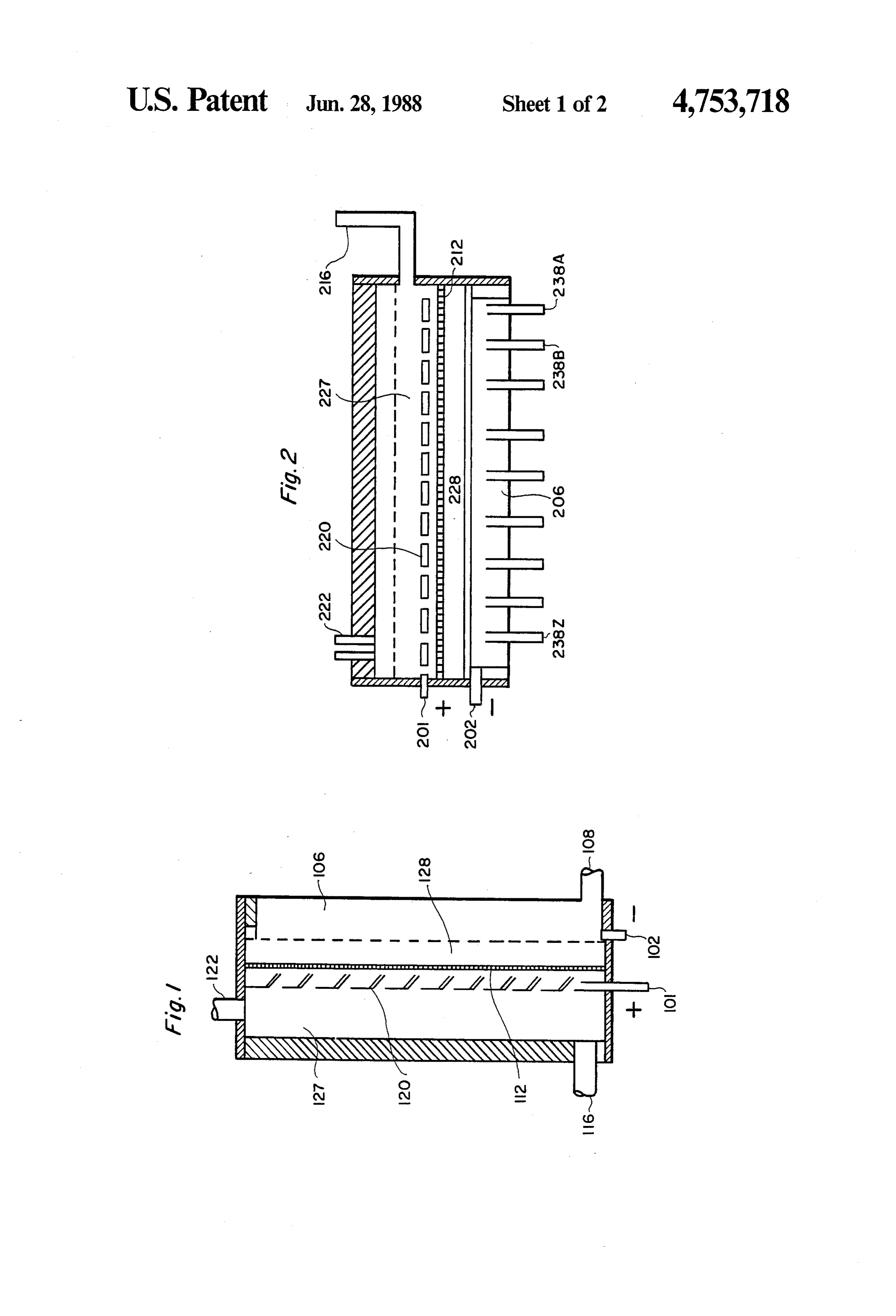
fresh solution into the space between the anode and the The separating means 112 may be a plurality of layers separating means. or a single layer. However, the material should be sub In another particularly desirable embodiment of the stantially inert to the chemicals that it will contact present invention the anode and cathode are disposed in under ordinary operating conditions. The separating a generally horizontal position at an angle of about 5 to means is constructed so that it has a somewhat limited 25. The cathode is above (superior to) both the anode ability to allow liquid to flow therethrough. Anode 120 and separating means, and is composed of granular is preferably equipped with louvres and is connected by particles supported by the separating means. The means conductor 101 to a positive source of voltage (not to urge the electrolyte from the electrolyte inlet and shown). Similarly cathode 106 is connected by conduc into the self-draining cathode is the static head of the 10 tor 102 to a negative source of voltage. electrolyte inlet above the electrolyte outlet and the In operation, electrolyte is introduced into the cell wicking effect of the porous separating means. through inlet port 116 and is urged through separating The cathode is an electrically conductive porous means 112 into the cathode compartment and into the mass having a plurality of pores and channels passing cathode 106. The liquid trickles down through the therethrough. It may be a bed of electroconductive 15 channels of the cathode by gravity and is collected and particles sintered to form a unitary mass or an agglom removed from the cell through electrolyte outlet port eration of loose particles. It must have pores of suffi 108. An electric potential or voltage is applied between cient size and number to allow gas to flow there anode 120 and cathode 106; at the anode oxygen gas is through. The channels must be of a sufficient size such formed, and rises as bubbles in the electrolyte between that nonvolatile products will flow by gravity from the 20 anode 120 and separating means 112. The bubbles are cathode, that is, the cathode should be "self-draining'. diverted by the louvres to the other side of anode 120, Another way of expressing this is to describe the chan and is then exhausted through port 122. At cathode 106 nels as being large enough so that gravity has a greater oxygen which diffuses from the air into the cathode 106 effect on the liquid in the electrode than does capillary is reduced to form hydrogen peroxide when it contacts pressure. 25 the electrolyte therein. The hydrogen peroxide rich The means to urge the electrolyte from the electro electrolyte trickles down inside the channels of cathode lyte inlet through the separating means and into the 106 and is collected at electrolyte outlet port 108. self-draining cathode and to controllably urge the elec For the purpose of this invention, the channels and trolyte through the separating means may be combined pores are distinguished in that in a channel the effect of by inclining the cell so that the electrolyte inlet is raised 30 gravity is greater on the electrolyte than the effect of above the electrolyte outlet. Alternatively, the electro capillary forces and in a pore the effect of gravity is less lyte may be urged by a pump or other means to provide on the electrolyte than the effect of capillary forces. a greater pressure at the electrolyte inlet, and the means In the cell, liquid flow through the separating means to controllably urge the electrolyte through the separat 12 should be controlled at a level sufficient to fill only ing means and into the self-draining cathode may be by 35 a portion of the pores in the cathode 106. If too much uniformly reducing the cross sectional area of the cell liquid passes through the separator and substantially all from the inlet end to the outlet end of the cell. of the pores of the cathode 106 are filled, oxygen gas is Any convenient separating means may be used in the displaced. This can result in the formation of explosive cell. For example, a ceramic diaphragm, anion selective hydrogen gas. Conversely, if too little electrolyte passes membrane such as a cation membrane which is also through the separating means 112, the electrochemical porous to the aqueous electrolyte. Other separating reactions will be minimized. The present invention pre means such as a microporous plastic, a mat of asbestos, vents the almost total filling of the cathode pores while woven or felted fibers or a porous plastic may also be at the same time preventing the almost total absence of suitable. Support may be required as part of the separat electrolyte from the cathode.
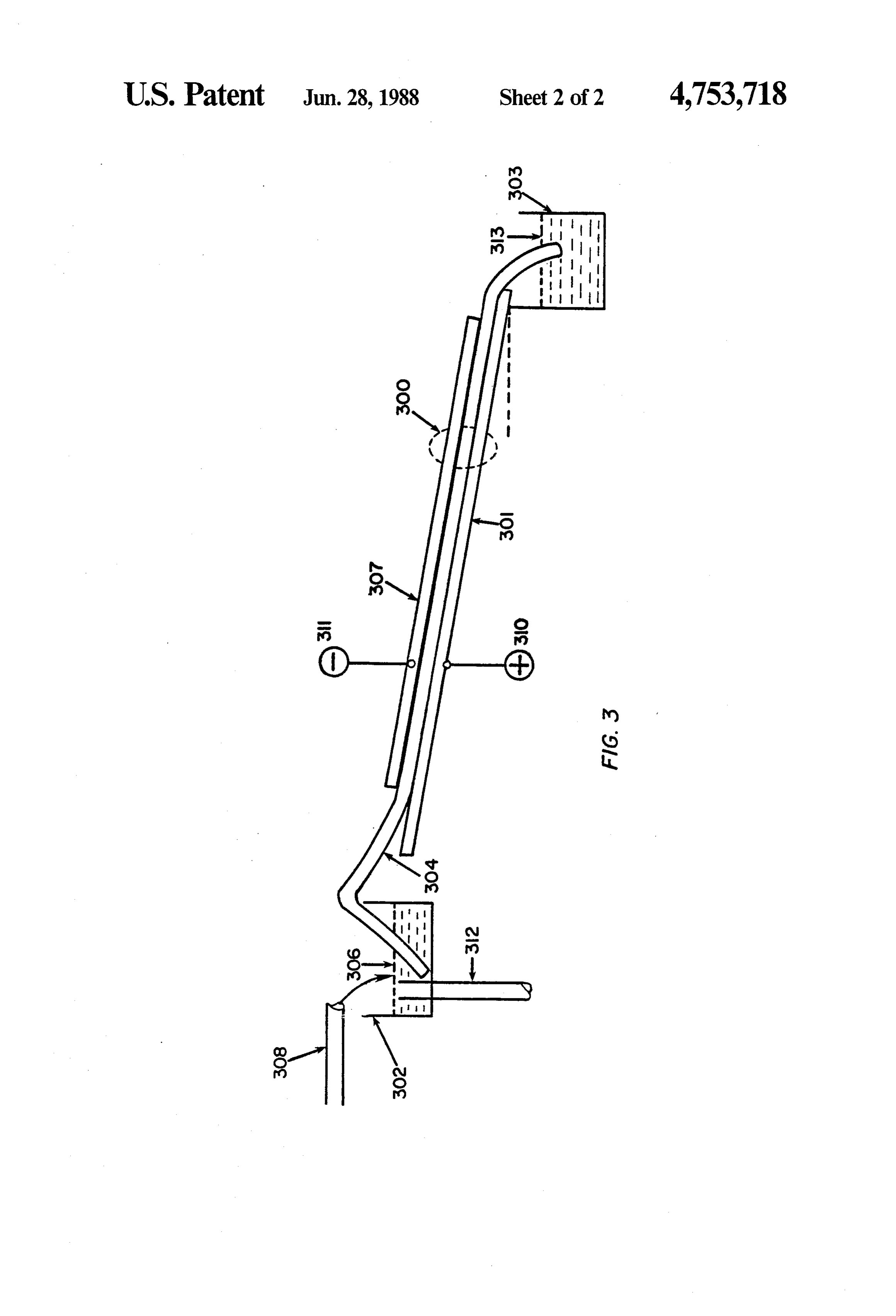
ing means. 45 FIG. 2 is similar to FIG. 1 except for the generally The following figures illustrate three of the preferred horizontal rather than vertical orientation of the cell. embodiments of the invention in detail. Each of the elements comprising the cell is enumerated FIG. 1 is a cross sectional view of a cell in which the similarly to the corresponding element of FIG. 1 except cathode, separating means and anode are disposed in a in the "200's', rather than "100's'. One exception is that generally vertical position. 50 the outlet port 108 is replaced by a plurality of small FIG. 2 is a cross sectional view of a cell in which the diameter outlet ports represented by 238A, 238B to cathode, separating means and anode are disposed in a 2382, which function as channels. Gravity acting on the generally horizontal position with the anode superior. electrolyte in the outlet ports provides a slight suction FIG. 3 is a cross sectional view of a cell in which the within cathode 206 drawing the electrolyte into the cathode, separating means and anode are disposed in a 55 outlet ports and thereby prevents the electrolyte from generally horizontal position with the cathode superior. filling the pores employed by oxygen gas. FIG. 1 illustrates an electrolytic cell. The cell has For the purposes of this invention, the term "gener louvred anode 120 which is located in an anolyte com ally horizontal' can include angles of up to about 45. It partment 127. An electrolyte inlet port 116 opens into is clear that the outlet ports 238A, 238B to 2382 need the anolyte compartment. A gaseous product outlet not be perpendicular to cathode 206. For example, the port 122 is located in the anolyte compartment 127. The outlet ports can be inclined at an angle to be essentially first surface of cathode 106 contacts the electrolyte in vertical even if cathode 206 is inclined from the absolute cathode compartment and the second surface forms an horizontal.
exterior surface of the cell and is in contact with an A view of another embodiment of the invention, cell oxygen containing gas such as air. An electrolyte outlet 65 300 is shown in FIG. 3.
port 108 collects liquid electrolyte from cathode. Sepa FIG. 3. Anode 301, a nickel or stainless steel plate, is rating means 112 divides the cell into anode compart disposed in a generally horizontal attitude between ment and cathode compartment. electrolyte reservoir 302 and electrolyte surge tank 303.
Page 6
A sheet of a polyester felt fabric 304 is supported on One method of controlling the pressure drop across anode 301 with a first end in reservoir 302 forming an the separating means of the cell of FIG. 1 is by operat electrolyte inlet and the second end in surge tank 303 to ing the anode compartment under gas or liquid pres form an electrolyte outlet. Electrolyte is urged through sure. In this method, the opposing compartment is the cell by the wicking action of polyester felt 304 and sealed from the atmosphere and gas pressure or liquid by the static head between the level of electrolyte in pressure is exerted on the electrolyte. Pumps may be reservoir 302 and the electrolyte surge tank 303. Reser used to force a pressurized liquid into the opposing voir 302 contains sufficient electrolyte 306 so that the compartment or the pressure may be maintained by a upper surface of electrolyte 306 is higher than the sec valve attached to ports 122 or 222.
ond end of polyester felt 304 at electrolyte surge tank 10 EXAMPLE 1.
303. An electroconductive cathode 307 composed of carbon black bonded to graphite chips is disposed to An electrolytic cell was constructed in accordance provide a first surface contacting and above polyester with FIG. 3. The cathodes were prepared in a manner felt 304. The second surface of the cathode forms an similar to U.S. Pat. Nos. 4,457,953 and 4,481,303 and exterior surface of cell 300. Cell 300 consists of anode 15 consisted of carbon black bonded to graphite chips 301, the portion of polyester felt 304 adjacent to the (-10 and +20 mesh) with colloidal polytetrafluoroeth anode, and cathode 307. The polyester felt 304 defining ylene (PTFE). The separating means was a commerical the space between the anode 301 and cathode 307 into 38 cmx 17 cm polyester felt 1.15 mm thick, and the an anode compartment (not shown) and a cathode con anode was a 27 cm x 19 cm nickel plate. A 12X 12 mesh partment (not shown but including part of cathode 307). 20 nickel screen was employed as a current collector. A Conduit means 308 provides electrolyte to electrolyte 3.7% solution of sodium hydroxide containing 0.05% reservoir 302 from a source (not shown). Conductors disodium EDTA was employed as the electrolyte. The 310 and 311 provide a voltage to anode 301 and cathode cell was inclined at an angle of about 12 and oxygen 307 respectively from a source (not shown). gas contacted the second surface of the cathode. The In operation electrolyte from reservoir 302 is drawn 25 average electrolyte flow rate was 8.3 g/min. The elec by the wicking effect of felt 304 into cell 300 where trolyte contained 0.7% H2O2 and current efficiency oxygen gas is formed. The oxygen is directed from the after 5 hours was calculated to be 72.3%. The current anode compartment by the felt 304 into the cathode density was 0.02 A/cm2 at a voltage of 1.3 v. compartment and to cathode 307 where it is reduced to 30 1.I claim:
An electrolytic cell for reducing oxygen to hydro hydrogen peroxide. Additional oxygen diffuses from the oxygen-containing gas at the electrolyte interface in gen peroxide at a cathode in the presence of an aqueous the surface of cathode 307 where it is also reduced to alkaline electrolyte comprising a cell having an electro hydrogen peroxide. The electrolyte is urged from the lyte inlet, a porous, self-draining cathode with a first electrolyte inlet to the electrolyte outlet by the static 35 forming contacting surface electrolyte and a second surface an exterior surface of the cell, an electrolyte head between the level of electrolyte in reservoir 302 outlet disposed to receive electrolyte draining from the and the electrolyte surge tank 303 in combination with cathode, an anode, separating means between the cath the wicking effect of separating means 304. ode and the anode defining an anode compartment con One skilled in the art will recognize that in the pres taining the electrolyte inlet and a cathode compartment, ent invention oxygen is always able to diffuse into cath the separating means being substantially ode because the cathode comprises an exterior surface the electrolyte, the second surface of the permeable cathode con
of the cell and is always in contact with the atmosphere. tacting an oxygen-containing gas, said cell having The cells exemplified in FIGS. 2 and 3 have an added means to controllably urge the electrolyte from the advantage over a substantially vertical cell in that the electrolyte inlet through the separating means and into hydrostatic pressures are uniform over the separating. 45 the self-draining cathode at a rate about equal to the means and the cathode so that the rate of diffusion of drainage rate of the oxygen into the cathode and the rate of flow of electro a quantity sufficient electrolyte from the cathode and in to fill only a portion of the pores of lyte through the separating means and into the cathode the cathode and having means to divert oxygen gas are also uniform throughout the cell.
There are two convenient methods for controlling 50 away from the separating means and means to exhaust a the flow through the separating means into the elec cell. the anode compartment out of the electrolytic gas in trode. One method is by varying the area of the separat ing means contacted by the liquid and a second method ode2. The is electrolytic cell of claim 1 wherein the cath substantially vertical and the means to divert is by adjusting the pressure drop across the separating oxygen gas in the anode compartment electrolyte away e2S. 55 from the separating means comprises louvres in the In a vertical cell a convenient way of controlling the anode.
area of the separating means exposed to the liquid is by 3. The electrolytic cell of claim 1 wherein the cath increasing or decreasing the height of the liquid reser ode is generally horizontal and the anode is permeable voir of the anode compartment adjoining the separating to a gas and is disposed in the cell in a position superior means. As the height is increased, the flow through the to the cathode and separating means, the means to di separating means increases. Conversely, as the height is vert oxygen gas away from the separating means and decreased, the flow decreases. However, this varies the out of the electrolytic cell is the permeable anode. area of cathode and anode in contact with the electro 4. An electrolytic cell for reducing oxygen to hydro lyte and hence the cell capacity. gen peroxide at a cathode in the presence of an aqueous Another method of controlling the flow through the 65 alkaline electrolyte comprising a cell having an electro separating means of a vertical cell is by controlling the lyte inlet, a generally horizontal, porous, self-draining pressure drop across the separating means. The pressure cathode with a first surface immersed in the electrolyte drop may be controlled in several ways. and a second surface forming an exterior surface of the
Page 7
cell, an electrolyte outlet disposed to receive electrolyte drainage rate of the electrolyte from the cathode and in draining from the cathode, the electrolyte inlet being a quantity sufficient to fill only a portion of the pores of above the electrolyte outlet to provide a static head, an the cathode and the porous separating means providing anode contacting the electrolyte, a porous separating means to divert oxygen gas away from the separating means contacting the first surface of the cathode and 5 means and the means to exhaust oxygen gas out of the the anode, and a current collector contacting the cath ode above the level of the electrolyte in the cathode, the electrolytic cell is the cathode. second surface of the cathode contacting an oxygen ode comprises carboncell 5. The electrolytic of claim 4 wherein the cath containing gas, the porous separating means and the by polytetrafluoroethylene. bonded to graphite chips black static head between the electrolyte inlet and the electro O lyte outlet controllably urging the electrolyte from the 6. The electrolytic cell of claim 4 wherein the cell is electrolyte inlet through the separating means and into inclined at an angle of from k about
the selfdraining cathode at a rate about equal to the
Provenance
- Collection
- Cited prior art
- Original PDF
- patentimages.storage.googleapis.com →
- Filed
- 1986-11-20
- Pages
- 7
- Method
- pdftotext (the PDF's own text layer) + pdftoppm 300dpi page scans
- Source
- Google Patents bibliographic record
- Granted
- 1988-06-28
- Inventors
- John S. C. Chiang; FMC Corp
- Transcribed from
- patentimages.storage.googleapis.com →