patent · US4740711
Pipeline built-in electric power generating set
26 April 1988
Page 1 — bibliographic record
United States Patent (19) 11 Patent Number: 4,740,711 Sato et al. (45) Date of Patent: Apr. 26, 1988 (54) PIPELINE BUILT-IN ELECTRIC POWER 56) References Cited
GENERATING SET
75 Inventors: Shoji Sato; Hiroyoshi Yamamoto; 3,936,681 2/1976 Liebe ................................ 290/52 X Yoshihiko Okuyama, all of 3,980,894 9/1976 Vary et al. ............................ 290/54 Kanagawa, Japan 4,176,283 11/1979 McLaren........... ... 290/52 4,445,046 4/1984 Allegreet al. ... 290/52
73) Assignee: Fuji Electric Co., Ltd., Kanagawa, FOREIGN PATENT DOCUMENTS Japan 55-104578 8/1980 Japan ..................................... 290/54 21 Appl. No.: 936,189 Primary Examiner-William M. Shoop, Jr. Assistant Examiner-W. E. Duncanson, Jr.
Attorney, Agent, or Firm-Finnegan, Henderson, (22 Filed: Dec. 1, 1986 Farabow, Garrett & Dunner Foreign Application Priority Data 57 ABSTRACT
Nov. 29, 1985 JP Japan ............................... 60-26863
An electric power generating set for a fluid pipeline,
Nov. 29, 1985 (JP) Japan ..... ... 60-268632 comprising a turbine coupled to the pipeline for rotating
Nov. 29, 1985 JP Japan ..... www.p 60-268633 under the pressure of the fluid moving in the pipeline; a
May 7, 1986 (JP) Japan ..... peo on to 61-104403 generator coupled to the downstream end of the turbine for generating electric power upon rotation, and a heat exchanger for communicating the fluid from the turbine 51) Int. Cl." .............................................. F03B 13/10 to the pipeline for absorbing heat from the generator. 52 U.S.C. ......................................... 249/52; 290/54 58 Field of Search .......................... 290/1, 43, 52, 54 8 Claims, 3 Drawing Sheets
HIGH
PRESSURE
Page 2
Drawing sheet — no readable text.
Page 3
Drawing sheet — no readable text.
Page 4
Drawing sheet — no readable text.
Page 5
coil and the cylinder means may include a sealed cylin
PPEL NE BUILT-N ELECTRIC POWER der through the stator core for receiving fluid from the GENERATING SET turbine means and communicating the fluid to the pipe
BACKGROUND OF THE INVENTION
line downstream from the generator means.
5 The generator means alternatively may include a 1. Field of the Invention shaft extending into the fluid in the pipeline and the heat This invention relates to an electric power generating exchange means also may include hollow in the shaft, set commonly used in steel plants, chemical plants or and an operating solution sealed in the follow for in the like which is steam or gas powered. creasing heat transfer from the generator means to the 10 fluid. Preferably, the shaft also includes a plurality of 2. Description of Prior Art
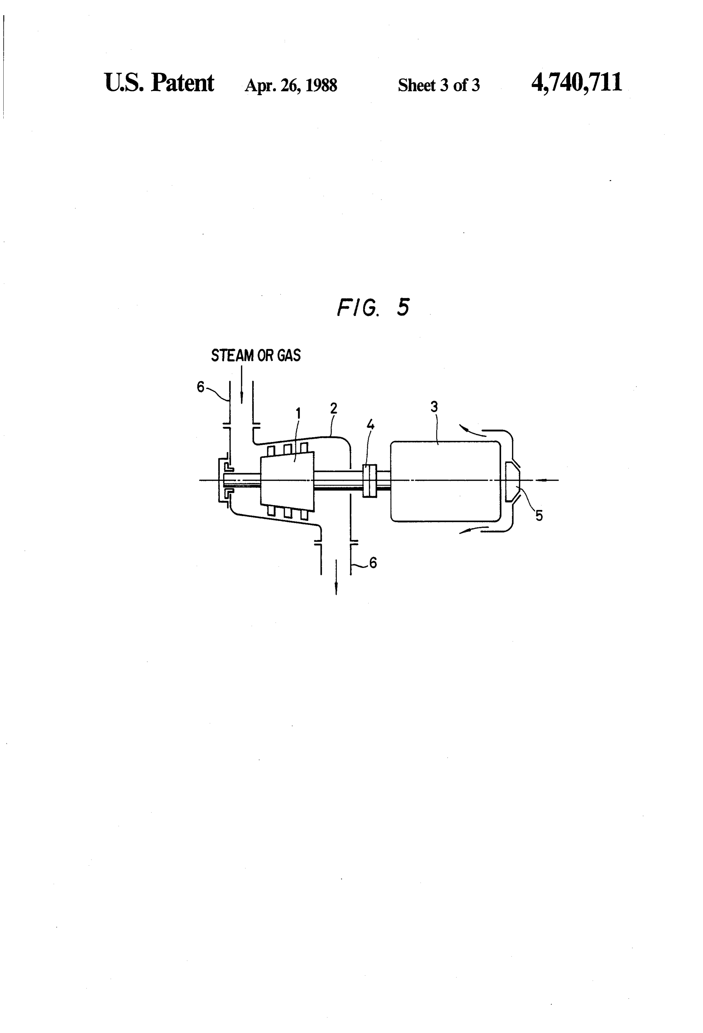
A conventional electric power generating set of this cooling fins for improving heat radiation from shaft to type is as shown in FIG. 5. In FIG. 5, reference numeral the fluid.
1 designates a steam turbine rotor (or gas turbine rotor), Thus, the generating set of the invention is a pipeline and 2, a steam turbine casing (or gas turbine casing). built-in type electric power generator set which is high The steam turbine (or gas turbine) is provided perpen 15 in operating efficiency, low in operating sound and dicular to a pipe line 6. A power generator 3 is con simple in supporting structure.
nected through a coupling 4 to the shaft of the steam turbine rotor (or gas turbine rotor). The generator 3 BRIEF DESCRIPTION OF THE DRAWINGS comprises a stator and a rotor. The generator 3 may be The accompanying drawings, which are incorpo connected through a reduction gear to the turbine ro 20 rated in and constitute a part of this specification, illus tor. A fan 5 is coupled to the other end of the power trate several embodiments of the invention, and to generator 3 so as to cool the latter 3. Thus, heat gener gether with the description, serve to explain the princi ated by the generator 3 is dissipated into the air.
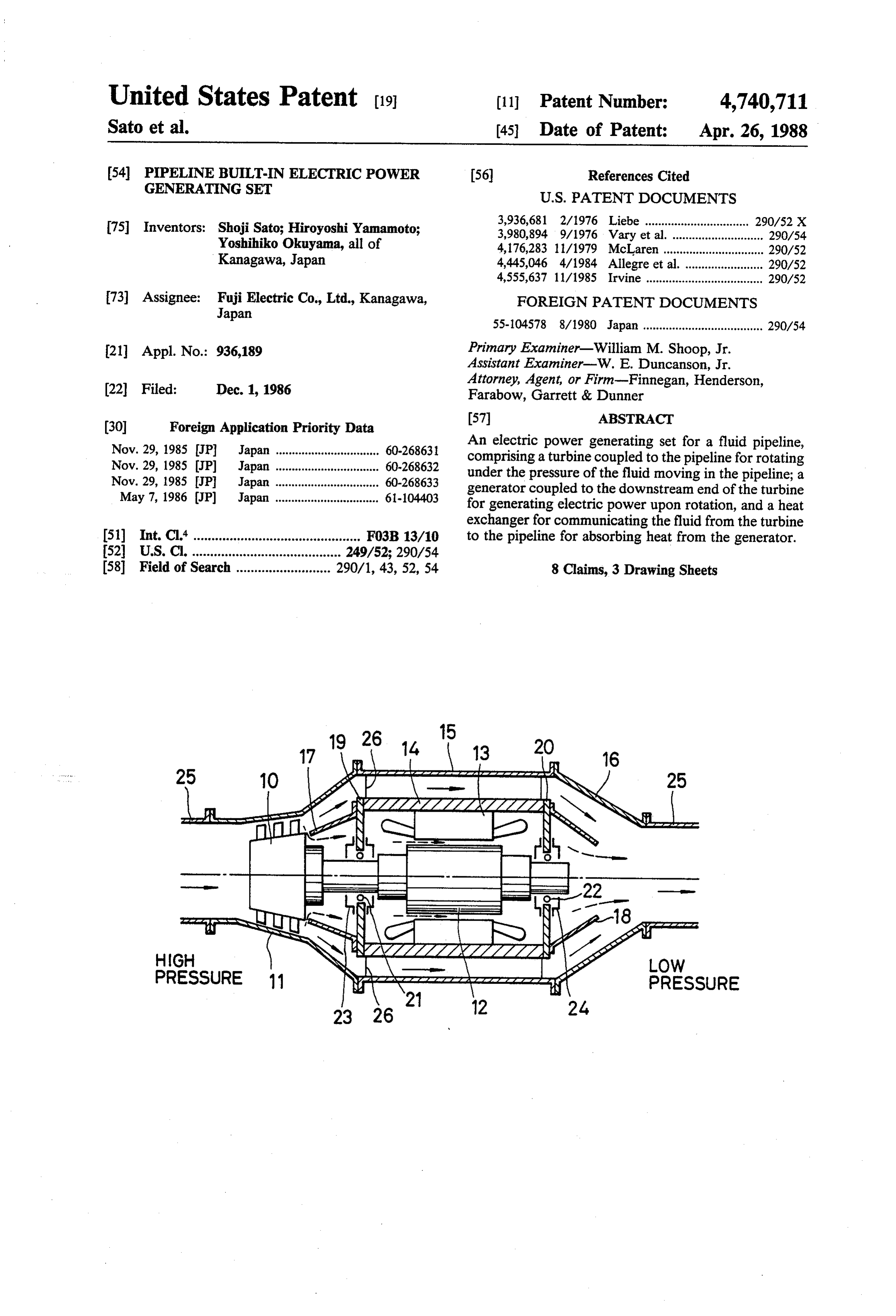
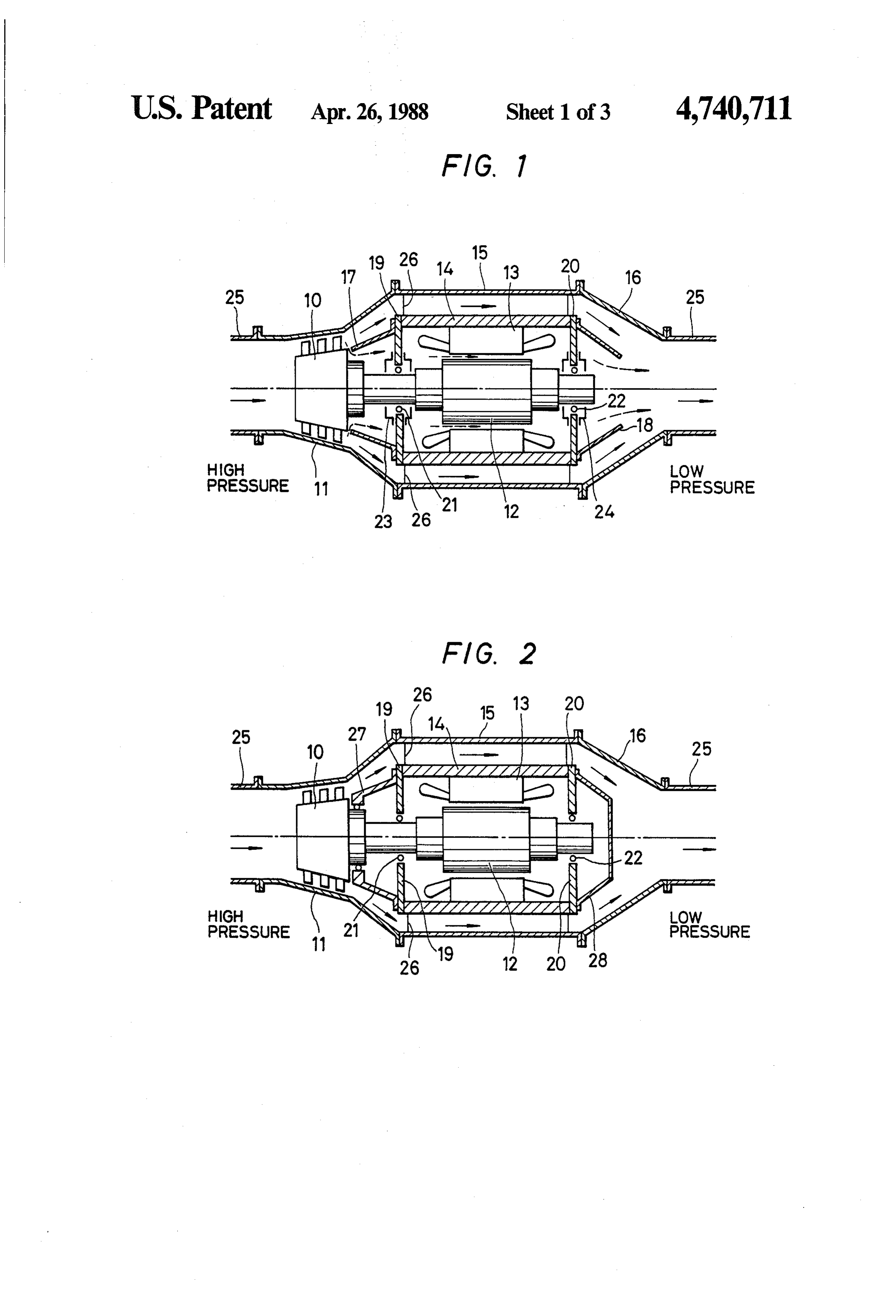
As is apparent from FIG. 5, the electric power gener plesFIG. of the invention of the drawings: ating set is coupled to a part of the pipeline 6. For eco 25 example1ofis aa pipeline longitudinal sectional view showing a first nomical use of the installation space, it is desirable that ating set according tobulit-in this type electric power gener invention;
the generating set by small in size. As it rotates as high FIG. 2 is a longitudinal sectional view showing a speed and acccordingly the cooling fan of the generator second example of the pipeline built-in type electric 3 also rotates at high speed, noise is produced. How ever, since the generating set is connected to the pipe 30 power generating set according to the invention in which the generator is completely sealed;
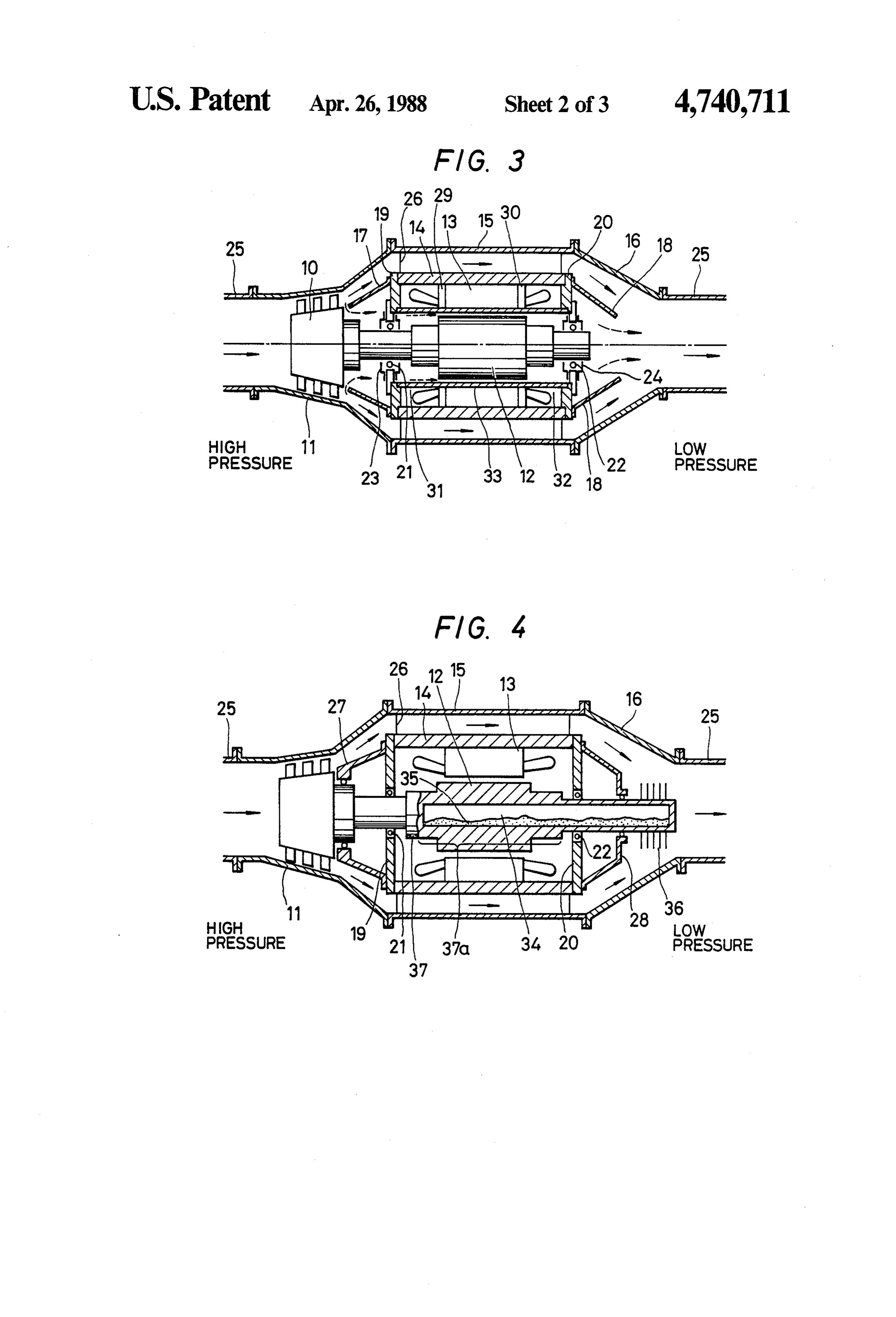
line 6, as was described above, it is difficult to suppress FIG. 3 is a longitudinal sectional view showing a the production of such noise.
Furthermore, since the generator normally is set per third example of the pipeline built-in type electric pendicular to the pipeline 6, it is liable to vibrate. The power generating set according to the invention in which the stator winding and the stator core of the vibration cannot be eliminated without firmly support 35 generator ing the pipeline 6 and the generator 3. are sealed; and FIG. 4 is also a longitudinal sectional view showing a
SUMMARY OF THE INVENTION fourth example of the pipeline built-in type electric Accordingly, it is an object of this invention to pro power generating set according to the invention in vide an electric power generating set which utilizes which the rotary shaft of the generator is used as a heat steam or gas to generate electric power in steel plants, radiating pipe. in which the rotary shaft of the genera chemical plants or the like, in which the power genera tor is used as a heat radiating pipe. tion efficiency is improved by recovering heat gener FIG. 5 is a conventional electric power generating set ated by the generator, noises produced thereby are of this type.
reduced, and the supporting structure is simple. 45
DESCRIPTION OF THE PREFERRED
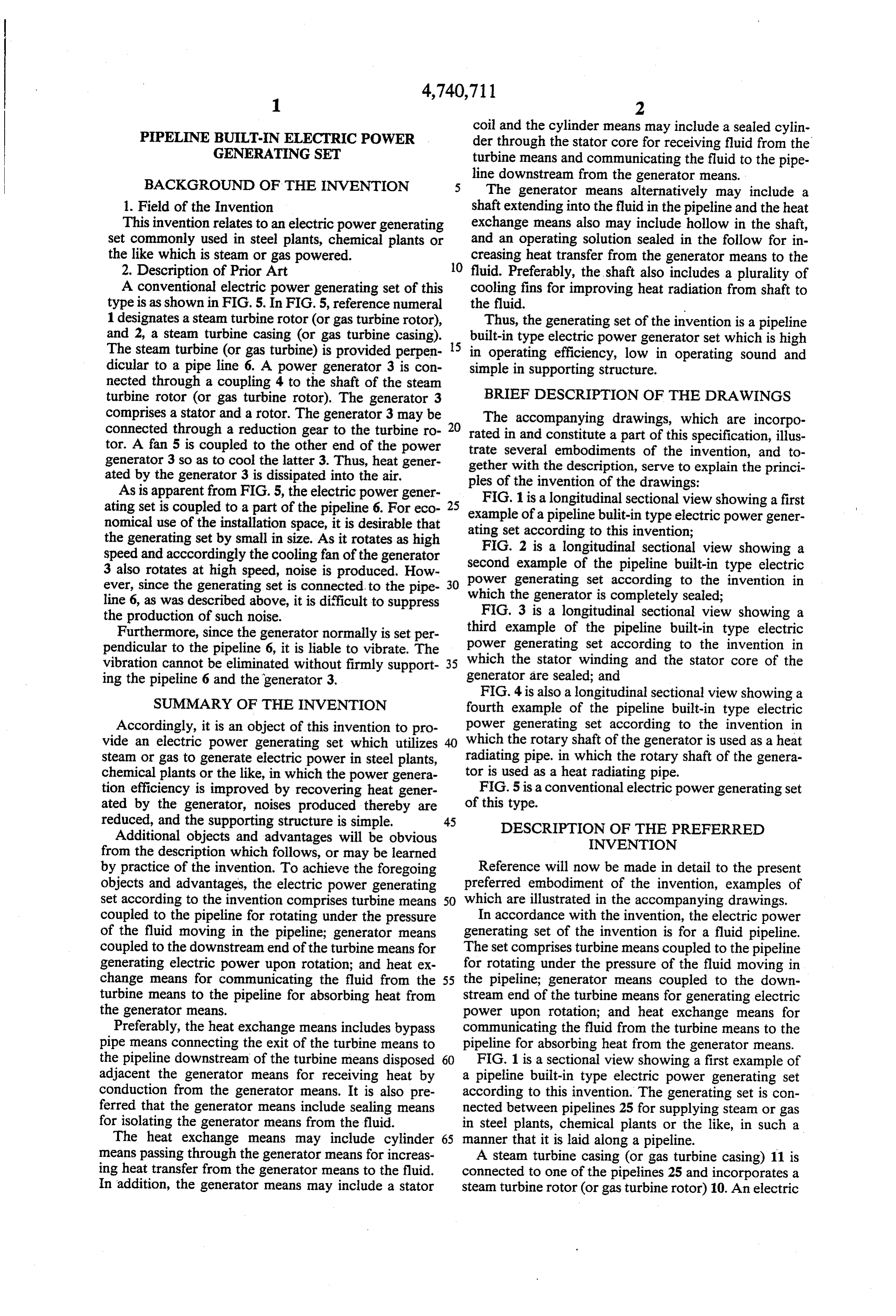
Additional objects and advantages will be obvious INVENTION from the description which follows, or may be learned by practice of the invention. To achieve the foregoing Reference will now be made in detail to the present objects and advantages, the electric power generating preferred embodiment of the invention, examples of set according to the invention comprises turbine means 50 which are illustrated in the accompanying drawings. coupled to the pipeline for rotating under the pressure In accordance with the invention, the electric power of the fluid moving in the pipeline; generator means generating set of the invention is for a fluid pipeline. coupled to the downstream end of the turbine means for The set comprises turbine means coupled to the pipeline generating electric power upon rotation; and heat ex for rotating under the pressure of the fluid moving in change means for communicating the fluid from the 55 the pipeline; generator means coupled to the down turbine means to the pipeline for absorbing heat from stream end of the turbine means for generating electric the generator means. power upon rotation; and heat exchange means for Preferably, the heat exchange means includes bypass communicating the fluid from the turbine means to the pipe means connecting the exit of the turbine means to pipeline for absorbing heat from the generator means. the pipeline downstream of the turbine means disposed 60 FIG. 1 is a sectional view showing a first example of adjacent the generator means for receiving heat by a pipeline built-in type electric power generating set conduction from the generator means. It is also pre according to this invention. The generating set is con ferred that the generator means include sealing means nected between pipelines 25 for supplying steam or gas for isolating the generator means from the fluid. in steel plants, chemical plants or the like, in such a The heat exchange means may include cylinder 65 manner that it is laid along a pipeline.
means passing through the generator means for increas A steam turbine casing (or gas turbine casing) 11 is ing heat transfer from the generator means to the fluid. connected to one of the pipelines 25 and incorporates a In addition, the generator means may include a stator steam turbine rotor (or gas turbine rotor) 10. An electric
Page 6
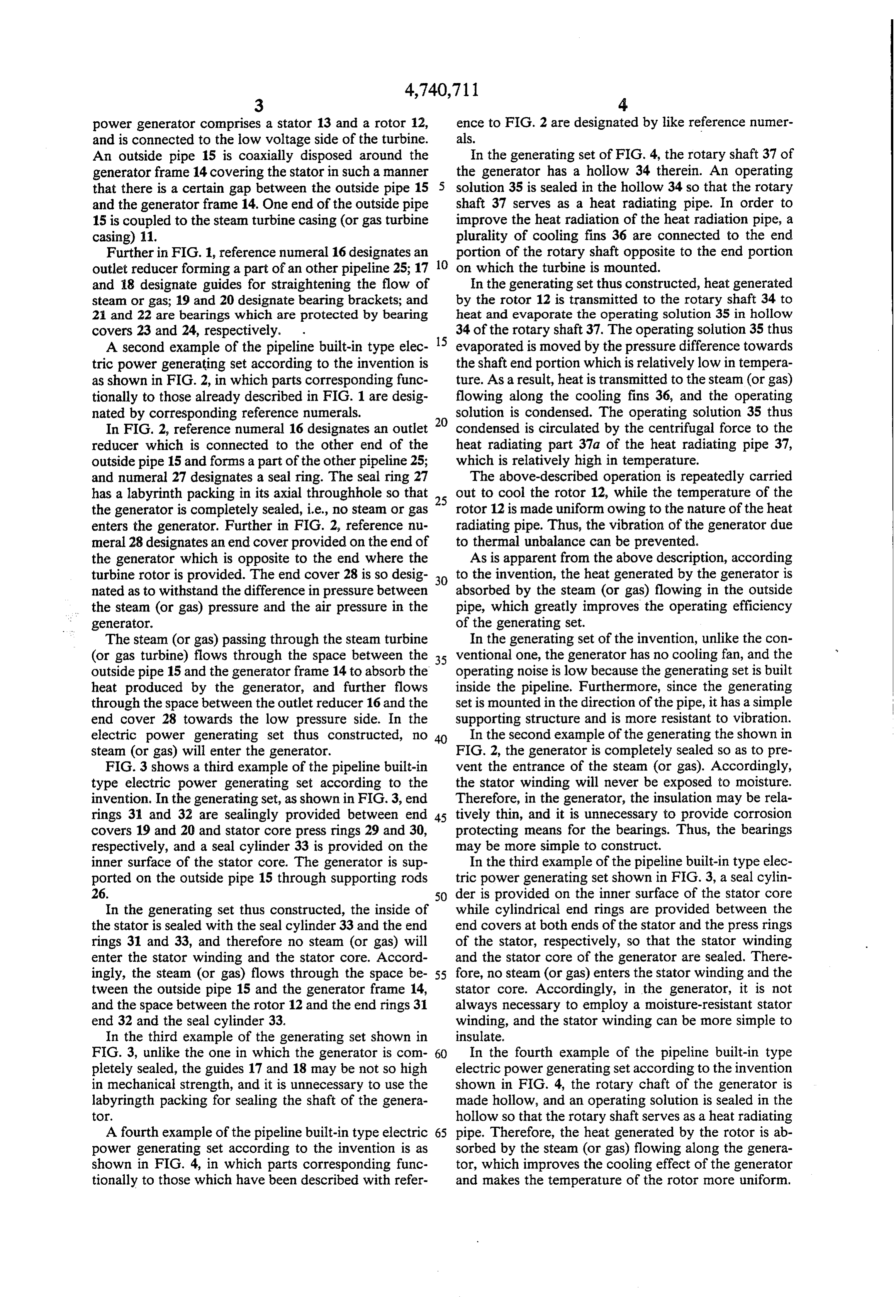
power generator comprises a stator 13 and a rotor 12, ence to FIG. 2 are designated by like reference numer and is connected to the low voltage side of the turbine. als.
An outside pipe 15 is coaxially disposed around the In the generating set of FIG. 4, the rotary shaft 37 of generator frame 14 covering the stator in such a manner the generator has a hollow 34 therein. An operating that there is a certain gap between the outside pipe 15 solution 35 is sealed in the hollow 34 so that the rotary and the generator frame 14. One end of the outside pipe shaft 37 serves as a heat radiating pipe. In order to 15 is coupled to the steam turbine casing (or gas turbine improve the heat radiation of the heat radiation pipe, a casing) 11. plurality of cooling fins 36 are connected to the end Further in FIG. 1, reference numeral 16 designates an portion of the rotary shaft opposite to the end portion outlet reducer forming a part of an other pipeline 25; 17 10 on which the turbine is mounted. and 18 designate guides for straightening the flow of In the generating set thus constructed, heat generated steam or gas; 19 and 20 designate bearing brackets; and by the rotor 12 is transmitted to the rotary shaft 34 to 21 and 22 are bearings which are protected by bearing heat and evaporate the operating solution 35 in hollow
34 of the rotary shaft 37. The operating solution 35 thus
A second example of the pipeline built-in type elec evaporated is moved by the pressure difference towards tric power generating set according to the invention is the shaft end portion which is relatively low in tempera as shown in FIG. 2, in which parts corresponding func ture. As a result, heat is transmitted to the steam (or gas) tionally to those already described in FIG. 1 are desig flowing along the cooling fins 36, and the operating nated by corresponding reference numerals. solution is condensed. The operating solution 35 thus In FIG. 2, reference numeral 16 designates an outlet condensed is circulated by the centrifugal force to the reducer which is connected to the other end of the heat radiating part 37a of the heat radiating pipe 37, outside pipe 15 and forms a part of the other pipeline 25; which is relatively high in temperature. and numeral 27 designates a seal ring. The seal ring 27 The above-described operation is repeatedly carried has a labyrinth packing in its axial throughhole so that 25 out to cool the rotor 12, while the temperature of the the generator is completely sealed, i.e., no steam or gas rotor 12 is made uniform owing to the nature of the heat enters the generator. Further in FIG. 2, reference nu radiating pipe. Thus, the vibration of the generator due meral 28 designates an end cover provided on the end of to thermal unbalance can be prevented. the generator which is opposite to the end where the As is apparent from the above description, according turbine rotor is provided. The end cover 28 is so desig 30 to the invention, the heat generated by the generator is nated as to withstand the difference in pressure between absorbed by the steam (or gas) flowing in the outside the steam (or gas) pressure and the air pressure in the pipe, which greatly improves the operating efficiency generator. of the generating set.
The steam (or gas) passing through the steam turbine In the generating set of the invention, unlike the con (or gas turbine) flows through the space between the 35 ventional one, the generator has no cooling fan, and the outside pipe 15 and the generator frame 14 to absorb the operating noise is low because the generating set is built heat produced by the generator, and further flows inside the pipeline. Furthermore, since the generating through the space between the outlet reducer 16 and the set is mounted in the direction of the pipe, it has a simple end cover 28 towards the low pressure side. In the supporting structure and is more resistant to vibration. electric power generating set thus constructed, no In the second example of the generating the shown in steam (or gas) will enter the generator. FIG. 2, the generator is completely sealed so as to pre FIG. 3 shows a third example of the pipeline built-in vent the entrance of the steam (or gas). Accordingly, type electric power generating set according to the the stator winding will never be exposed to moisture. invention. In the generating set, as shown in FIG. 3, end Therefore, in the generator, the insulation may be rela rings 3 and 32 are sealingly provided between end 45 tively thin, and it is unnecessary to provide corrosion covers 19 and 20 and stator core press rings 29 and 30, protecting means for the bearings. Thus, the bearings respectively, and a seal cylinder 33 is provided on the may be more simple to construct.
inner surface of the stator core. The generator is sup In the third example of the pipeline built-in type elec ported on the outside pipe 15 through supporting rods tric power generating set shown in FIG. 3, a seal cylin 26. 50 der is provided on the inner surface of the stator core In the generating set thus constructed, the inside of while cylindrical end rings are provided between the the stator is sealed with the seal cylinder 33 and the end end covers at both ends of the stator and the press rings rings 31 and 33, and therefore no steam (or gas) will of the stator, respectively, so that the stator winding enter the stator winding and the stator core. Accord and the stator core of the generator are sealed. There ingly, the steam (or gas) flows through the space be 55 fore, no steam (or gas) enters the stator winding and the tween the outside pipe 15 and the generator frame 14, stator core. Accordingly, in the generator, it is not and the space between the rotor 12 and the end rings 31 always necessary to employ a moisture-resistant stator end 32 and the seal cylinder 33. winding, and the stator winding can be more simple to In the third example of the generating set shown in insulate.
FIG. 3, unlike the one in which the generator is com 60 In the fourth example of the pipeline built-in type pletely sealed, the guides 17 and 18 may be not so high electric power generating set according to the invention in mechanical strength, and it is unnecessary to use the shown in FIG. 4, the rotary chaft of the generator is labyringth packing for sealing the shaft of the genera made hollow, and an operating solution is sealed in the to. hollow so that the rotary shaft serves as a heat radiating A fourth example of the pipeline built-in type electric 65 pipe. Therefore, the heat generated by the rotor is ab power generating set according to the invention is as sorbed by the steam (or gas) flowing along the genera shown in FIG. 4, in which parts corresponding func tor, which improves the cooling effect of the generator tionally to those which have been described with refer and makes the temperature of the rotor more uniform.
Page 7
Additional modifications and variations may be made cating the fluid to the pipeline downstream from the in the invention without departing from the scope or generator means.
spirit of the invention. 5. The generating set of claim 1 wherein the genera What is claimed is: tor means includes a shaft extending into the fluid in the 1. An electric power generating set for a fluid pipe pipeline, and the heat exchange means also includes a line, comprising: hollow in the shaft, and an operating solution sealed in turbine means coupled to the pipeline for rotating the hollow for increasing heat transfer from the genera tor means to the fluid.
under the pressure of the fluid moving in the pipe 6. The generating set of claim 5 wherein the shaft also line; 10 includes plurality of cooling fins for improving heat generator means coupled to the downstream end of radiation from the shaft to the fluid.
the turbine means for generating electric power 7. An electric power generating set for a gas pipeline, upon rotation; and comprising:
heat exchange means for communicating the fluid turbine means coupled to the pipeline for rotating from the turbine means to the pipeline and for 15 under the pressure of the gas moving in the pipe transferring heat from the generator means to the line;
fluid, the heat exchange means including bypass generator means coupled to the downstream end of pipe means connecting the exit of the turbine means the turbine means for generating electric power to the pipeline downstream of the generator means upon rotation; and and disposed adjacent the generator means for 20 heat exchange means for communicating the gas from receiving heat by conduction from the generator the turbine means to the pipeline and for transfer 62.S. ring heat from the generator means to the gas. 2. The generating set of claim 1 wherein the genera 8. An electric power generating set for a steam pipe tor means includes sealing means for isolating the gener 25 line, comprising:
ator means from the fluid. turbine means coupled to the pipeline for rotating 3. The generating set of claim 1 wherein the heat under the pressure of the steam moving in the pipe exchange means also includes cylinder means passing line;
through the generator means for increasing heat trans generator means coupled to the downstream end of fer from the generator means to the fluid. the turbine means for generating electric power 30 upon rotation; and 4. The generating set of claim 3 wherein generator heat exchange means for communicating the steam means includes a stator core and the cylinder means from the turbine means to the pipeline and transfer includes a sealed cylinder through the statar core for ring heat from the generator means to the steam. receiving fluid from the turbine means and communi :k se xk is
Provenance
- Collection
- Cited prior art
- Original PDF
- patentimages.storage.googleapis.com →
- Filed
- 1986-12-01
- Pages
- 7
- Method
- pdftotext (the PDF's own text layer) + pdftoppm 300dpi page scans
- Source
- Google Patents bibliographic record
- Granted
- 1988-04-26
- Inventors
- Shoji Sato; Hiroyoshi Yamamoto; Yoshihiko Okuyama; Fuji Electric Co Ltd
- Transcribed from
- patentimages.storage.googleapis.com →