patent · US5193899
Planar light-source device and illumination apparatus using the same
16 March 1993
Page 1 — bibliographic record
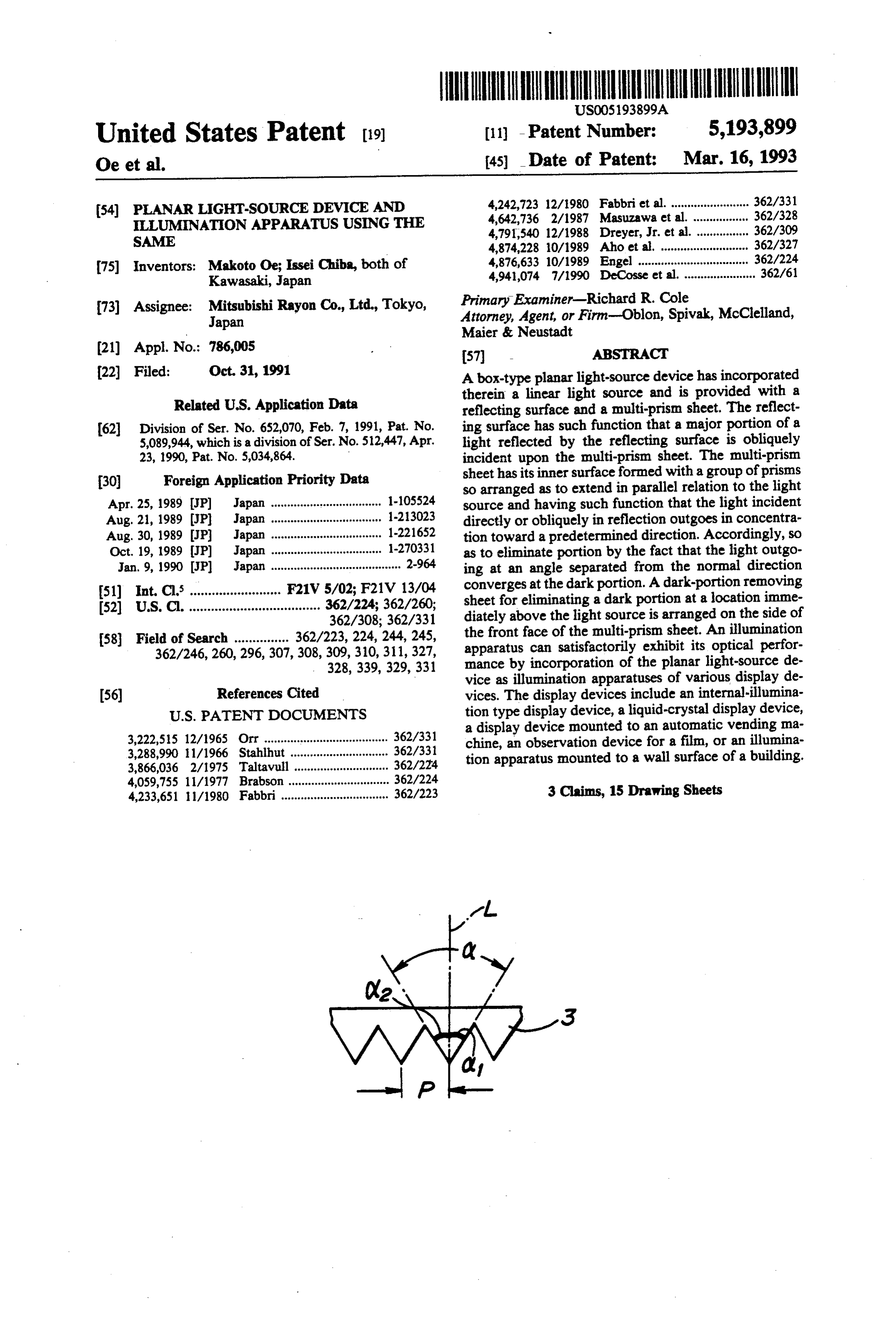
United States Patent (19) (11) - Patent Number: 5,193,899 Oe et al. 45) Date of Patent: Mar. 16, 1993 (54) PLANAR LIGHT-SOURCE DEVICE AND 4,242,723 12/1980 Fabbri et al. ........................ 362/.331 LLUMNATION APPARATUS USNG THE 4,642,736 2/1987 Masuzawa et al. ................. 362/328 4,791,540 12/1988 Dreyer, Jr. et al. ................ 362/309
SAME 4,874,228 0/1989 Aho et al. ..... . 362/327 4,876,633 10/1989 Engel ........ . 362/224 (75) Inventors: Makoto Oe; Issei Chiba, both of 4,941,074 7/1990 DeCosse et ... 362/61 Kawasaki, Japan 73) Assignee: Mitsubishi Rayon Co., Ltd., Tokyo, Primary Examiner-Richard R. Cole Japan Attorney, Agent, or Firm-Oblon, Spivak, McClelland, Maier & Neustadt (21) Appl. No.: 786,005 57 ABSTRACT 22 Filed: Oct. 31, 1991 A box-type planar light-source device has incorporated therein a linear light source and is provided with a
Related U.S. Application Data reflecting surface and a multi-prism sheet. The reflect 62) Division of Ser. No. 652,070, Feb. 7, 1991, Pat. No. ing surface has such function that a major portion of a 5,089,944, which is a division of Ser. No. 512,447, Apr. light reflected by the reflecting surface is obliquely 23, 1990, Pat. No. 5,034,864. incident upon the multi-prism sheet. The multi-prism 30) Foreign Application Priority Data sheet has its inner surface formed with a group of prisms so arranged as to extend in parallel relation to the light
Apr. 25, 1989 (JP) Japan .................................. 1.105524 source and having such function that the light incident Aug. 21, 1989 JP Japan .................................. 1-23023 directly or obliquely in reflection outgoes in concentra Aug. 30, 1989 JP Japan .................................. 1-221652 tion toward a predetermined direction. Accordingly, so Oct. 19, 1989 (JP) Japan ... . 1-270331 as to eliminate portion by the fact that the light outgo Jan. 9, 1990 (JP) Japan ........................................ 2-964 ing at an angle separated from the normal direction 51) int. Cl. ......................... F21V 5/02; F21V 13/04 converges at the dark portion. A dark-portion removing 52) U.S. Cl. ...... ee on a he so so 362/224; 362/260;
sheet for eliminating a dark portion at a location imme 362/308; 362/331 diately above the light source is arranged on the side of (58) Field of Search ............... 362/223, 224, 244, 245, the front face of the multi-prism sheet. An illumination 362/246, 260,296, 307, 308,309, 310, 311, 327, apparatus can satisfactorily exhibit its optical perfor 328,339, 329, 331 mance by incorporation of the planar light-source de vice as illumination apparatuses of various display de (56) References Cited vices. The display devices include an internal-illumina
a display device mounted to an automatic vending ma 3,222,515 12/1965 Orr ...................................... 362/331 chine, an observation device for a film, or an illumina 3,288,990 1 1/1966 Stahlhut .............................. 362/331 tion apparatus mounted to a wall surface of a building. 3,866,036 2/1975 Taltavull ............................. 362/224 4,059,755 1 1/1977 Brabson ............................... 362/224 4,233,651 1/1980 Fabbri ................................. 362/223 3 Claims, 15 Drawing Sheets
Page 2
Drawing sheet — no readable text.
Page 3
Drawing sheet — no readable text.
Page 4
Drawing sheet — no readable text.
Page 5
Drawing sheet — no readable text.
Page 6
Drawing sheet — no readable text.
Page 7
Drawing sheet — no readable text.
Page 8
Drawing sheet — no readable text.
Page 9
Drawing sheet — no readable text.
Page 10
Drawing sheet — no readable text.
Page 11
Drawing sheet — no readable text.
Page 12
Drawing sheet — no readable text.
Page 13
Drawing sheet — no readable text.
Page 14
Drawing sheet — no readable text.
Page 15
Drawing sheet — no readable text.
Page 16
Drawing sheet — no readable text.
Page 17
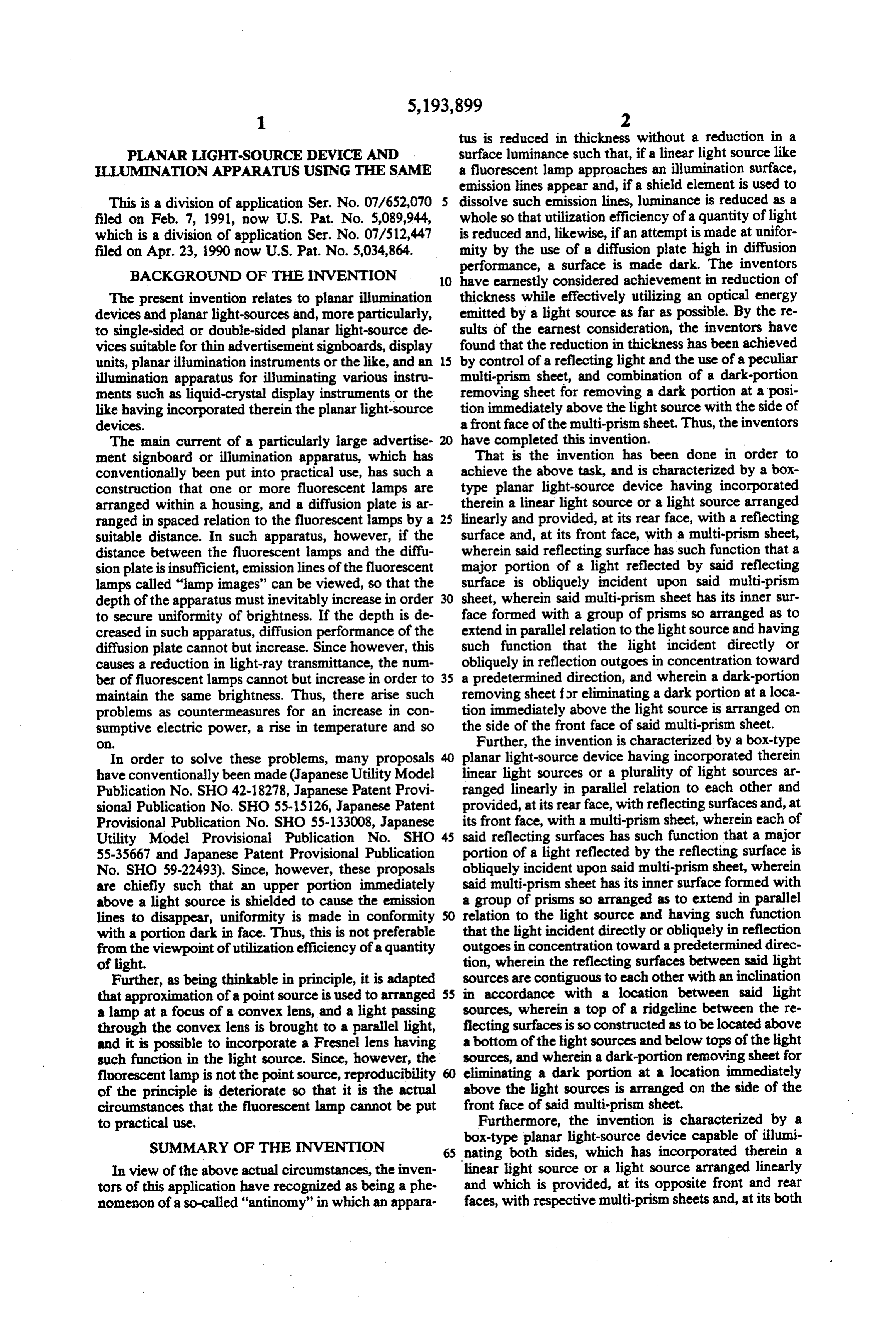
tus is reduced in thickness without a reduction in a
PLANAR LIGHT-SOURCE DEVICE AND surface luminance such that, if a linear light source like LLUMINATION APPARATUS USING THE SAME a fluorescent lamp approaches an illumination surface, emission lines appear and, if a shield element is used to
This is a division of application Ser. No. 07/652,070 dissolve such emission lines, luminance is reduced as a filed on Feb. 7, 1991, now U.S. Pat. No. 5,089,944, whole so that utilization efficiency of a quantity of light which is a division of application Ser. No. 07/512,447 is reduced and, likewise, if an attempt is made at unifor filed on Apr. 23, 1990 now U.S. Pat. No. 5,034,864. mity by the use of a diffusion plate high in diffusion
BACKGROUND OF THE INVENTION
performance, a surface is made dark. The inventors
O have earnestly considered achievement in reduction of
The present invention relates to planar illumination thickness while effectively utilizing an optical energy devices and planar light-sources and, more particularly, emitted by a light source as far as possible. By the re to single-sided or double-sided planar light-source de sults of the earnest consideration, the inventors have vices suitable for thin advertisement signboards, display found that the reduction in thickness has been achieved units, planar illumination instruments or the like, and an 15 by control of a reflecting light and the use of a peculiar illumination apparatus for illuminating various instru multi-prism sheet, and combination of a dark-portion ments such as liquid-crystal display instruments or the removing sheet for removing a dark portion at a posi like having incorporated therein the planar light-source tion immediately above the light source with the side of devices. afront face of the multi-prism sheet. Thus, the inventors The main current of a particularly large advertise 20 have completed this invention.
ment signboard or illumination apparatus, which has That is the invention has been done in order to conventionally been put into practical use, has such a achieve the above task, and is characterized by a box construction that one or more fluorescent lamps are type planar light-source device having incorporated arranged within a housing, and a diffusion plate is ar therein a linear light source or a light source arranged ranged in spaced relation to the fluorescent lamps by a 25 linearly and provided, at its rear face, with a reflecting suitable distance. In such apparatus, however, if the surface and, at its front face, with a multi-prism sheet, distance between the fluorescent lamps and the diffu wherein said reflecting surface has such function that a sion plate is insufficient, emission lines of the fluorescent major portion of a light reflected by said reflecting lamps called "lamp images' can be viewed, so that the surface is obliquely incident upon said multi-prism depth of the apparatus must inevitably increase in order sheet, wherein said multi-prism sheet has its inner sur to secure uniformity of brightness. If the depth is de face formed with a group of prisms so arranged as to creased in such apparatus, diffusion performance of the extend in parallel relation to the light source and having diffusion plate cannot but increase. Since however, this such function that the light incident directly or causes a reduction in light-ray transmittance, the num obliquely in reflection outgoes in concentration toward ber of fluorescent lamps cannot but increase in order to 35 a predetermined direction, and wherein a dark-portion maintain the same brightness. Thus, there arise such removing sheet for eliminating a dark portion at a loca problems as countermeasures for an increase in con tion immediately above the light source is arranged on sumptive electric power, a rise in temperature and so the side of the front face of said multi-prism sheet. O. Further, the invention is characterized by a box-type In order to solve these problems, many proposals planar light-source device having incorporated therein have conventionally been made (Japanese Utility Model linear light sources or a plurality of light sources ar Publication No. SHO 42-18278, Japanese Patent Provi ranged linearly in parallel relation to each other and sional Publication No. SHO 55-15126, Japanese Patent provided, at its rear face, with reflecting surfaces and, at Provisional Publication No. SHO 55-133008, Japanese its front face, with a multi-prism sheet, wherein each of Utility Model Provisional Publication No. SHO 45 said reflecting surfaces has such function that a major 55-35667 and Japanese Patent Provisional Publication portion of a light reflected by the reflecting surface is No. SHO 59-22493). Since, however, these proposals obliquely incident upon said multi-prism sheet, wherein are chiefly such that an upper portion immediately said multi-prism sheet has its inner surface formed with above a light source is shielded to cause the emission a group of prisms so arranged as to extend in parallel lines to disappear, unifornity is made in conformity relation to the light source and having such function with a portion dark in face. Thus, this is not preferable that the light incident directly or obliquely in reflection from the viewpoint of utilization efficiency of a quantity outgoes in concentration toward a predetermined direc of light. tion, wherein the reflecting surfaces between said light Further, as being thinkable in principle, it is adapted sources are contiguous to each other with an inclination that approximation of a point source is used to arranged 55 in accordance with a location between said light a lamp at a focus of a convex lens, and a light passing sources, wherein a top of a ridgeline between the re through the convex lens is brought to a parallel light, flecting surfaces is so constructed as to be located above and it is possible to incorporate a Fresnel lens having a bottom of the light sources and below tops of the light such function in the light source. Since, however, the sources, and wherein a dark-portion removing sheet for fluorescent lamp is not the point source, reproducibility eliminating a dark portion at a location immediately of the principle is deteriorate so that it is the actual above the light sources is arranged on the side of the circumstances that the fluorescent lamp cannot be put front face of said multi-prism sheet. to practical use. Furthermore, the invention is characterized by a box-type planar light-source device capable of illumi
SUMMARY OF THE INVENTION 65 nating both sides, which has incorporated therein a In view of the above actual circumstances, the inven linear light source or a light source arranged linearly tors of this application have recognized as being a phe and which is provided, at its opposite front and rear nomenon of a so-called "antinomy” in which an appara faces, with respective multi-prism sheets and, at its both
Page 18
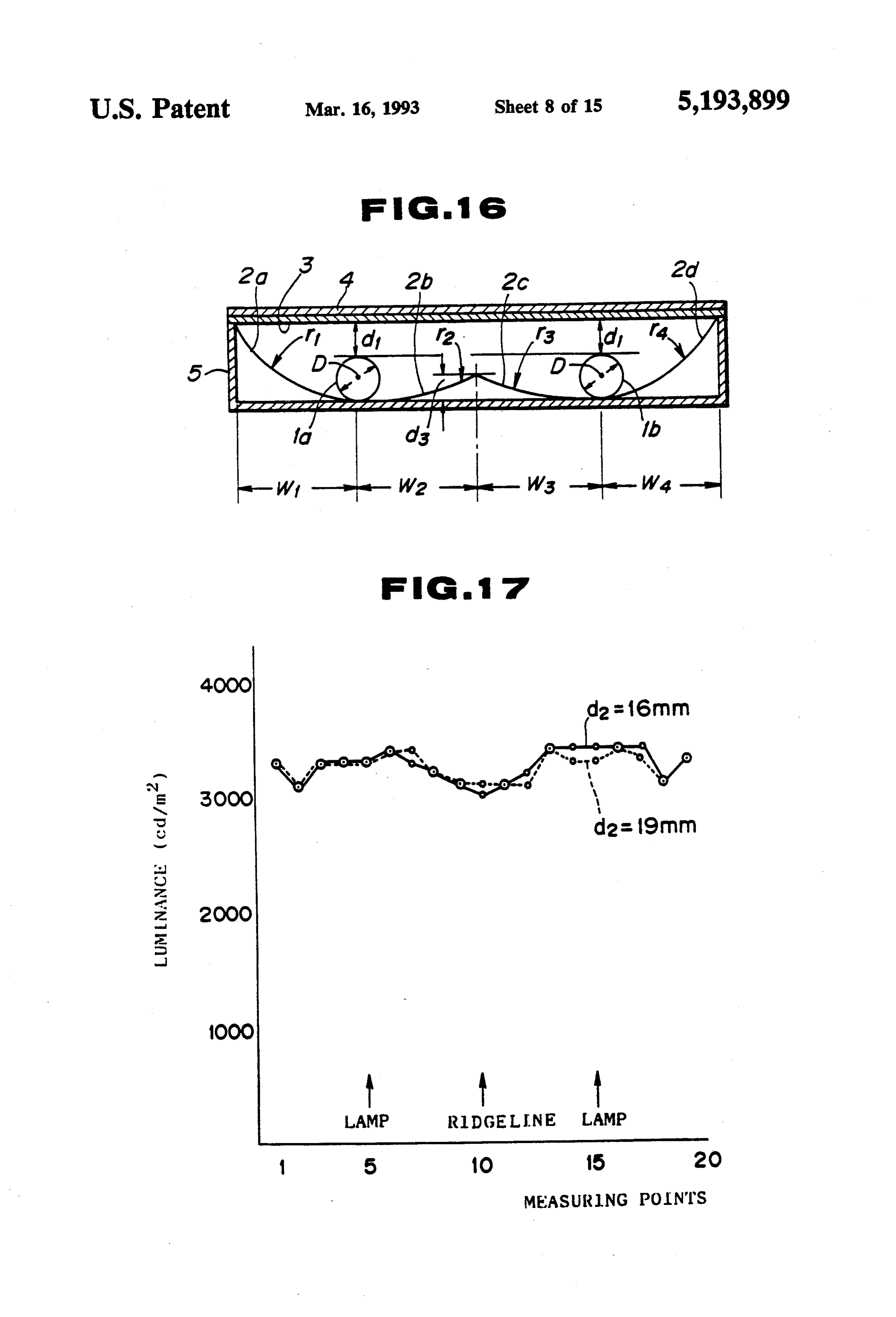
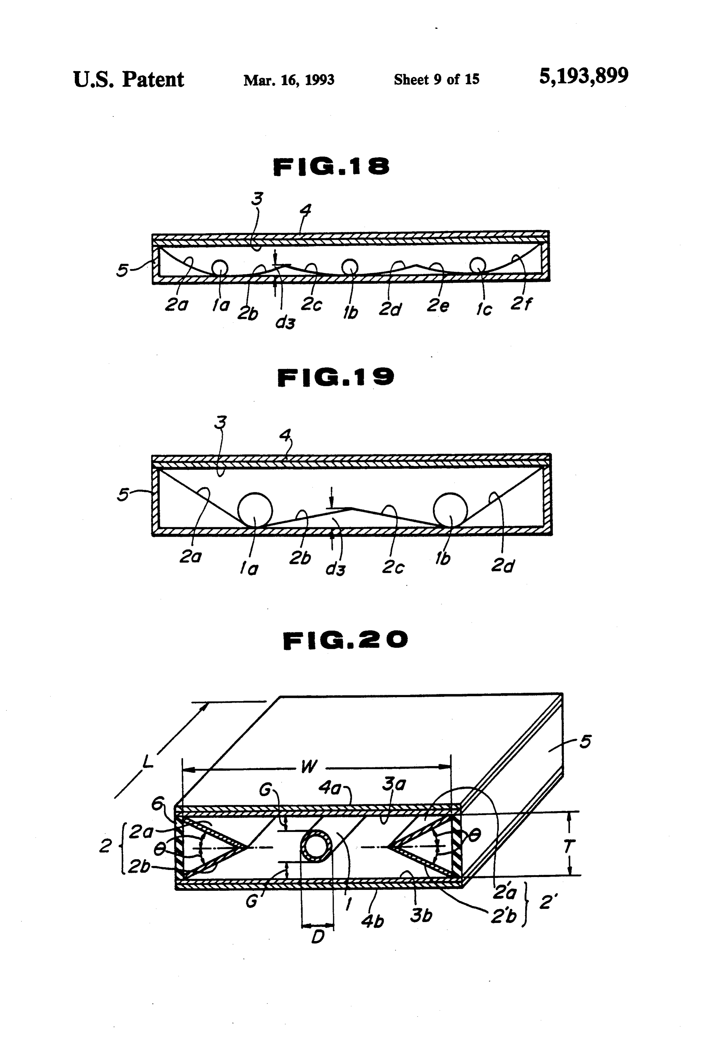
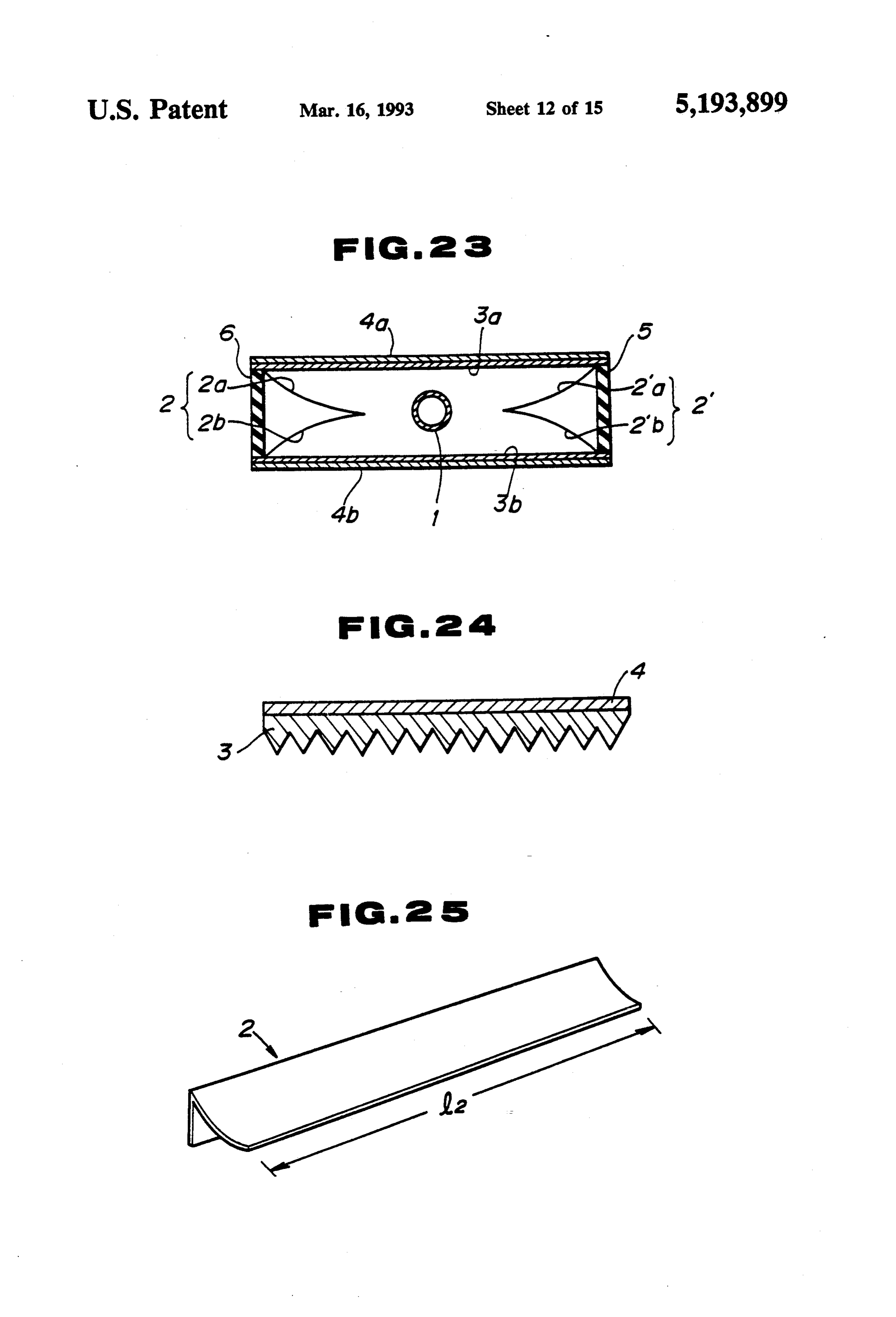
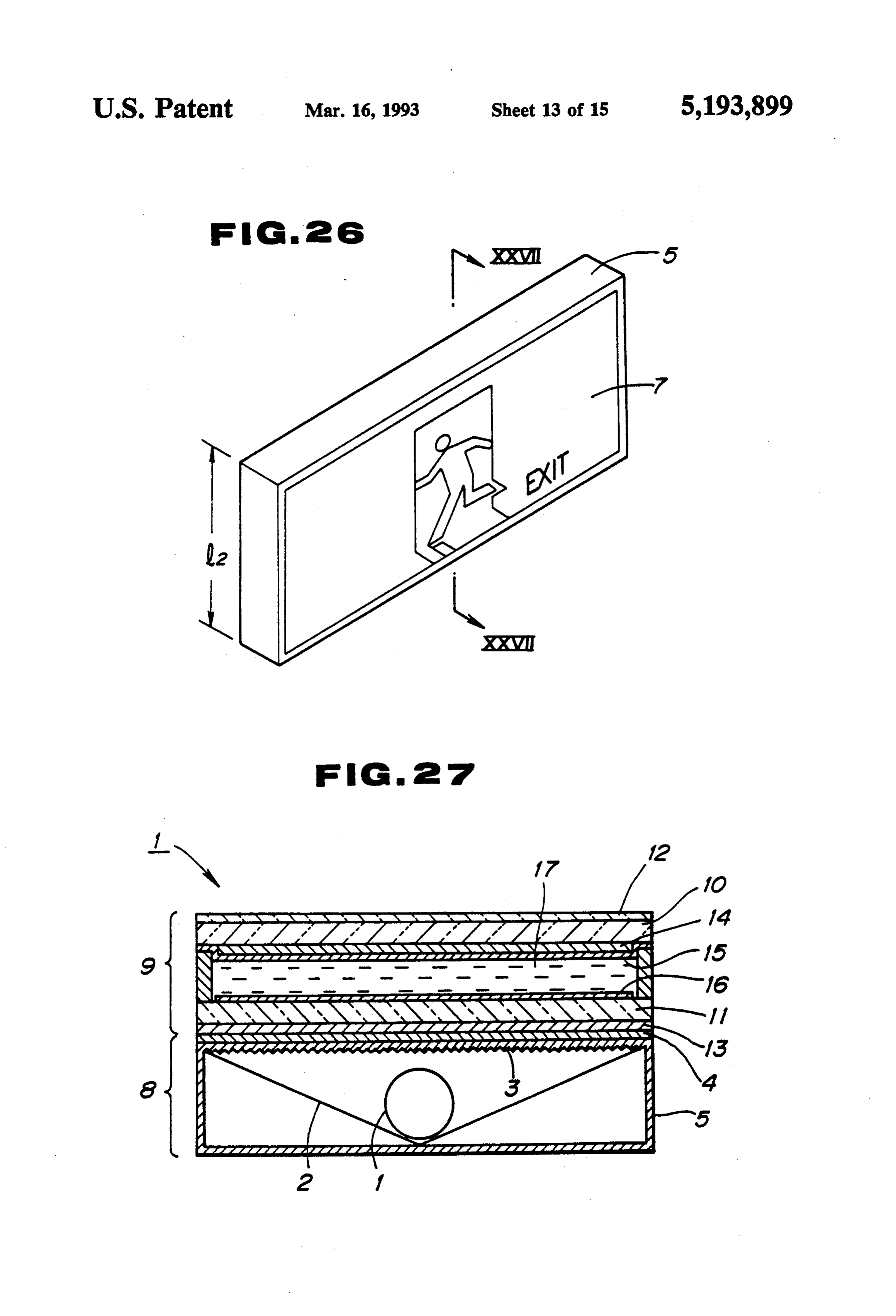
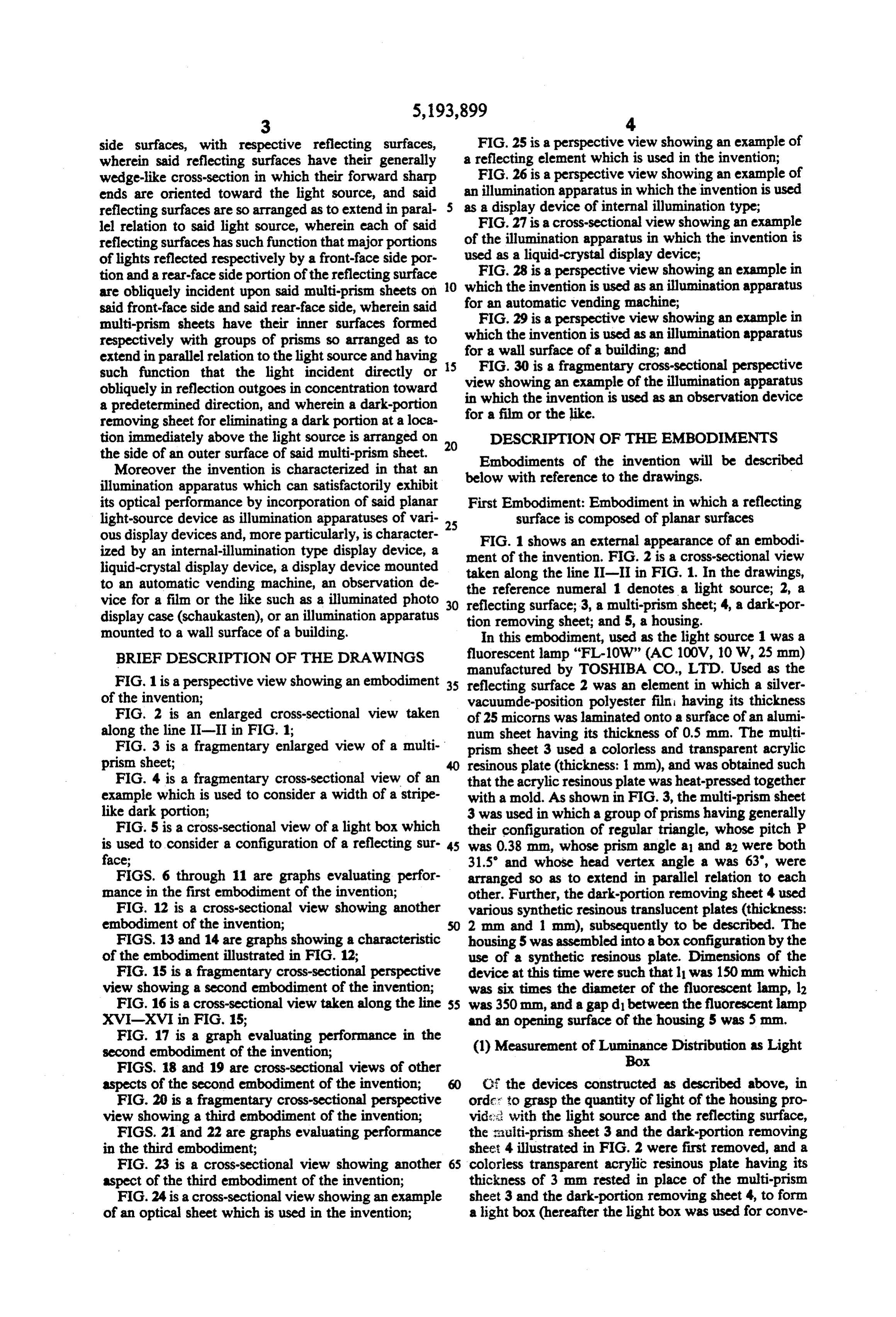
side surfaces, with respective reflecting surfaces, FIG.25 is a perspective view showing an example of wherein said reflecting surfaces have their generally a reflecting element which is used in the invention; wedge-like cross-section in which their forward sharp FIG. 26 is a perspective view showing an example of ends are oriented toward the light source, and said an illumination apparatus in which the invention is used reflecting surfaces are so arranged as to extend in paral as a display device of internal illumination type; lel relation to said light source, wherein each of said FIG. 27 is a cross-sectional view showing an example reflecting surfaces has such function that major portions of the illumination apparatus in which the invention is of lights reflected respectively by a front-face side por used as a liquid-crystal display device; tion and a rear-face side portion of the reflecting surface O FIG. 28 is a perspective view showing an example in are obliquely incident upon said multi-prism sheets on which the invention is used as an illumination apparatus said front-face side and said rear-face side, wherein said forFIG.29 an automatic vending machine;
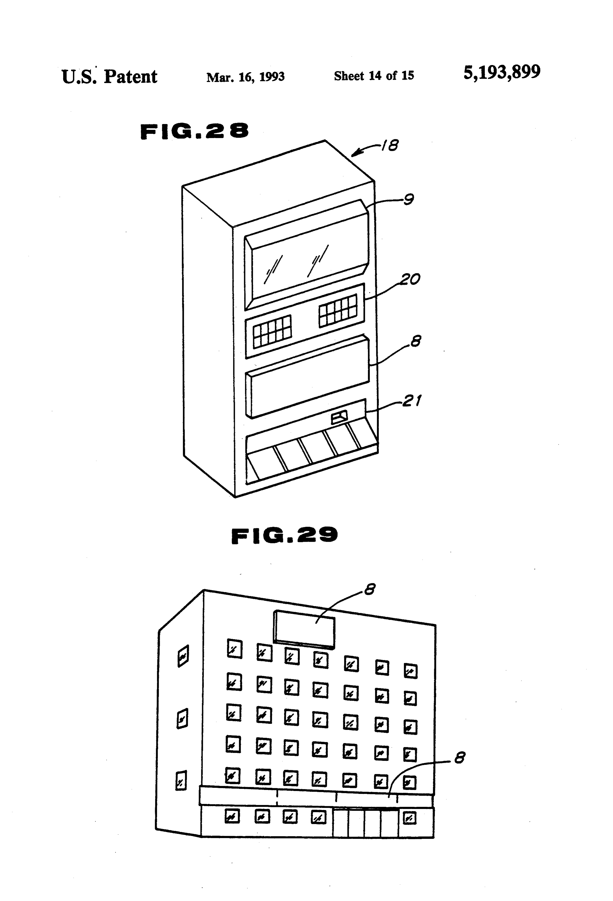
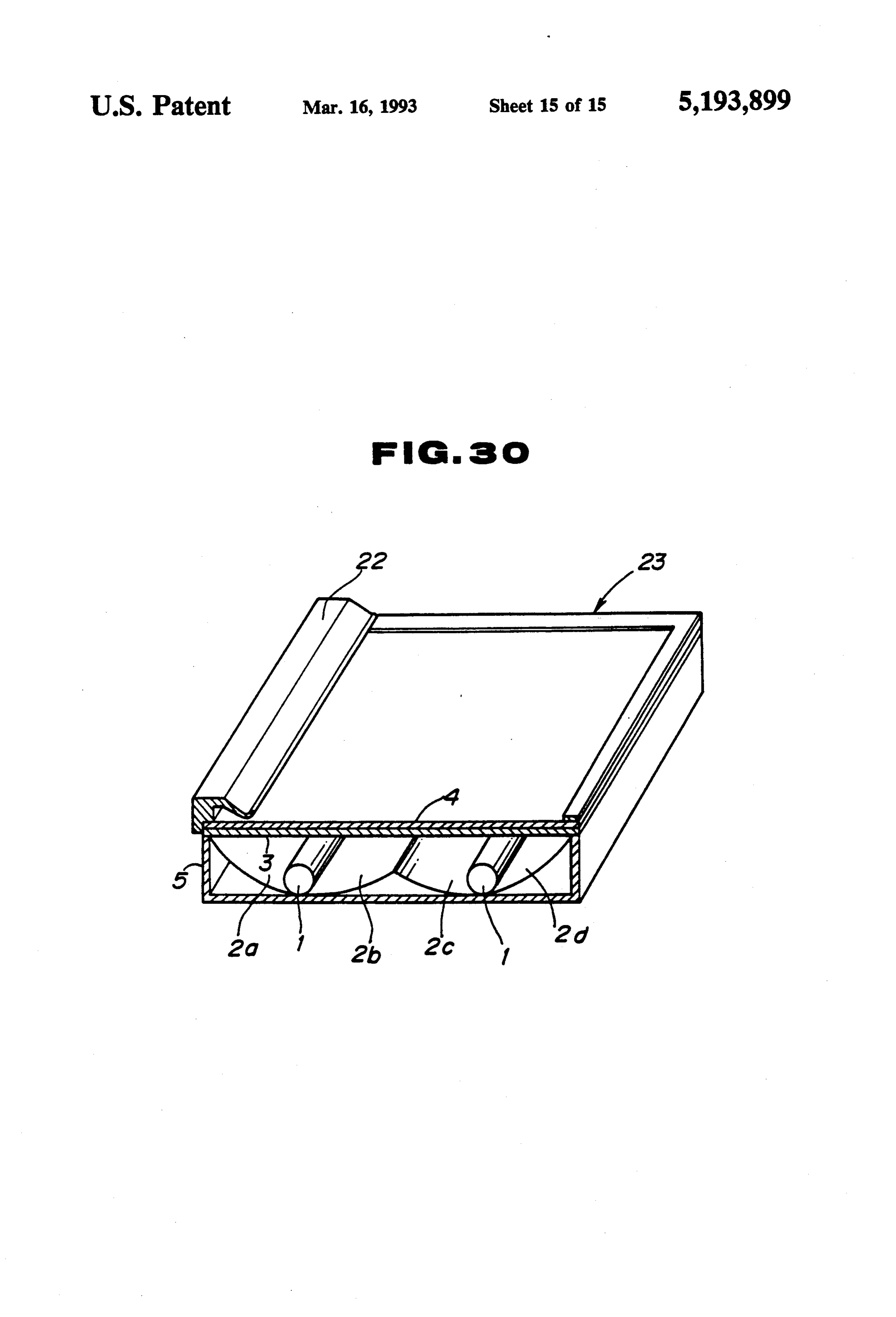
is a perspective view showing an example in multi-prism sheets have their inner surfaces formed which the invention is used as an illumination apparatus respectively with groups of prisms so arranged as to extend in parallel relation to the light source and having for a wall surface of a building; and such function that the light incident directly or view FIG. 30 is a fragmentary cross-sectional perspective obliquely in reflection outgoes in concentration toward showing an example of the illumination apparatus a predetermined direction, and wherein a dark-portion in which the invention is used as an observation device removing sheet for eliminating a dark portion at a loca for a film or the like.
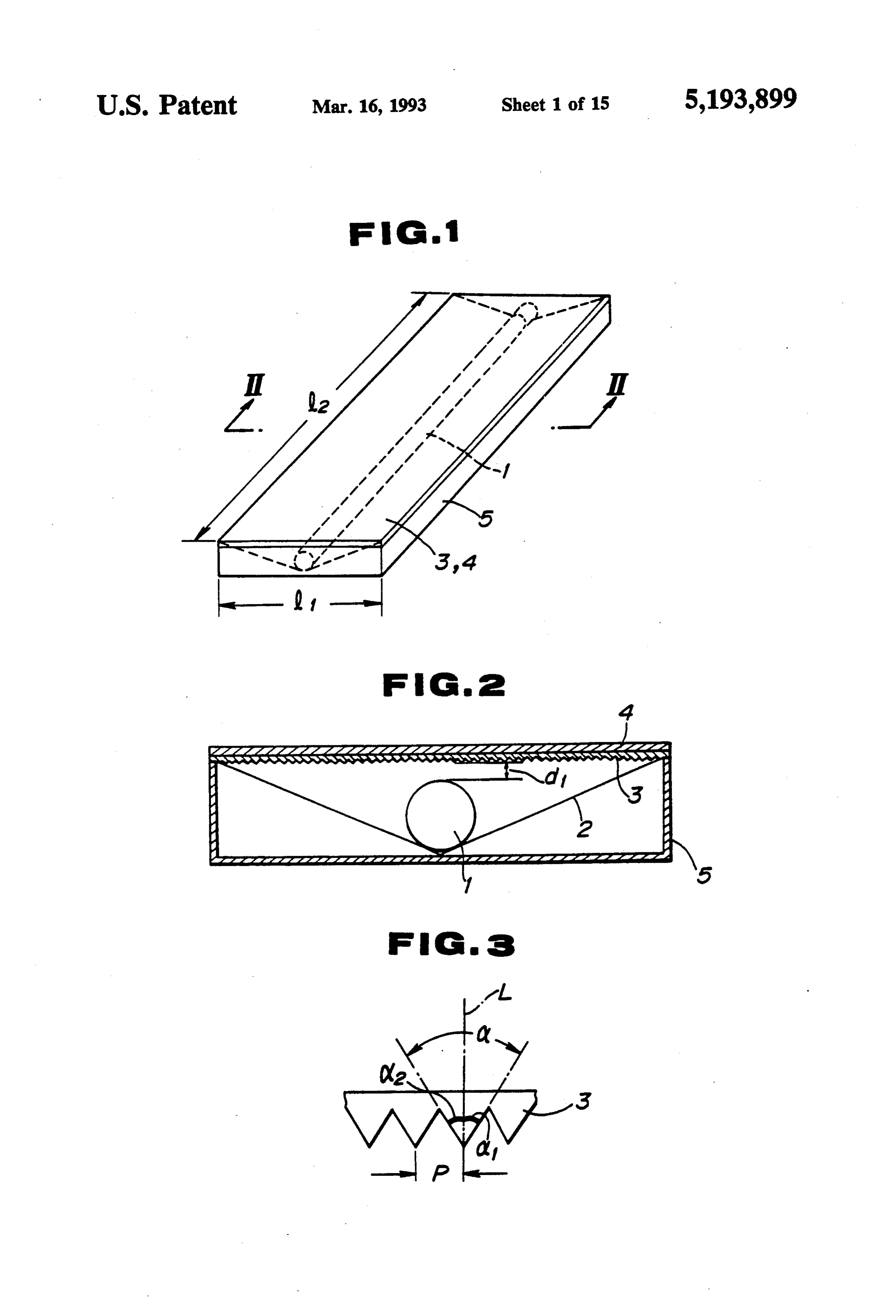
tion immediately above the light source is arranged on DESCRIPTION OF THE EMBODIMENTS the side of an outer surface of said multi-prism sheet. 20 Embodiments of the invention will be described Moreover the invention is characterized in that an illumination apparatus which can satisfactorily exhibit below with reference to the drawings. its optical performance by incorporation of said planar First Embodiment: Embodiment in which a reflecting light-source device as illumination apparatuses of vari surface is composed of planar surfaces ous display devices and, more particularly, is character 25 FIG. 1 shows an external appearance of an embodi ized by an internal-illumination type display device, a ment of the invention. FIG. 2 is a cross-sectional view liquid-crystal display device, a display device mounted taken along the line II-II in FIG. 1. In the drawings, to an automatic vending machine, an observation de the reference numeral 1 denotes a light source; 2, a vice for a film or the like such as a illuminated photo 30 reflecting surface; 3, a multi-prism sheet; 4, a dark-por display case (schaukasten), or an illumination apparatus tion removing sheet; and 5, a housing. mounted to a wall surface of a building. In this embodiment, used as the light source 1 was a BRIEF DESCRIPTION OF THE DRAWINGs fluorescent lamp "FL-10W" (AC 100V, 10 W, 25 mm) manufactured by TOSHIBA CO., LTD. Used as the
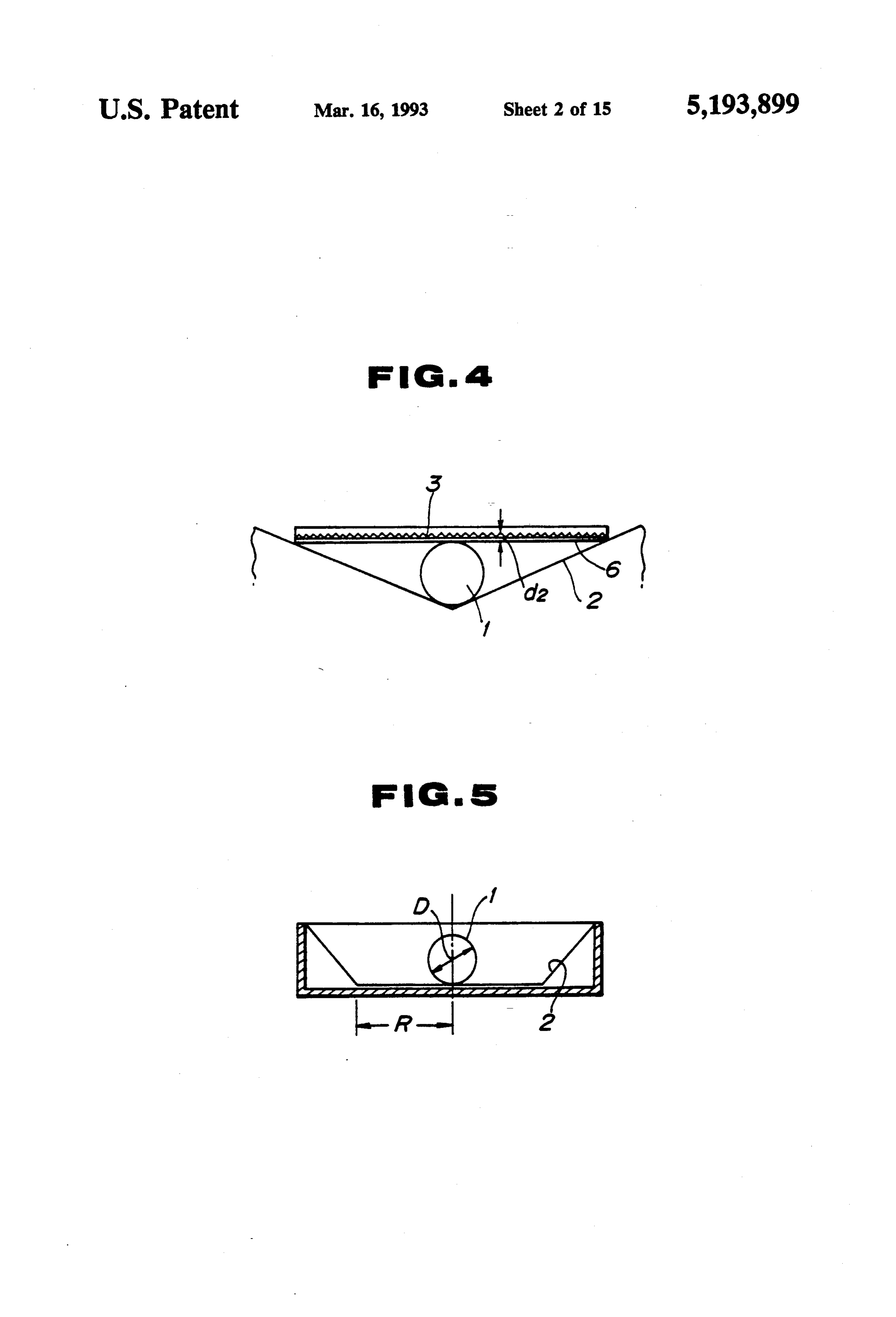
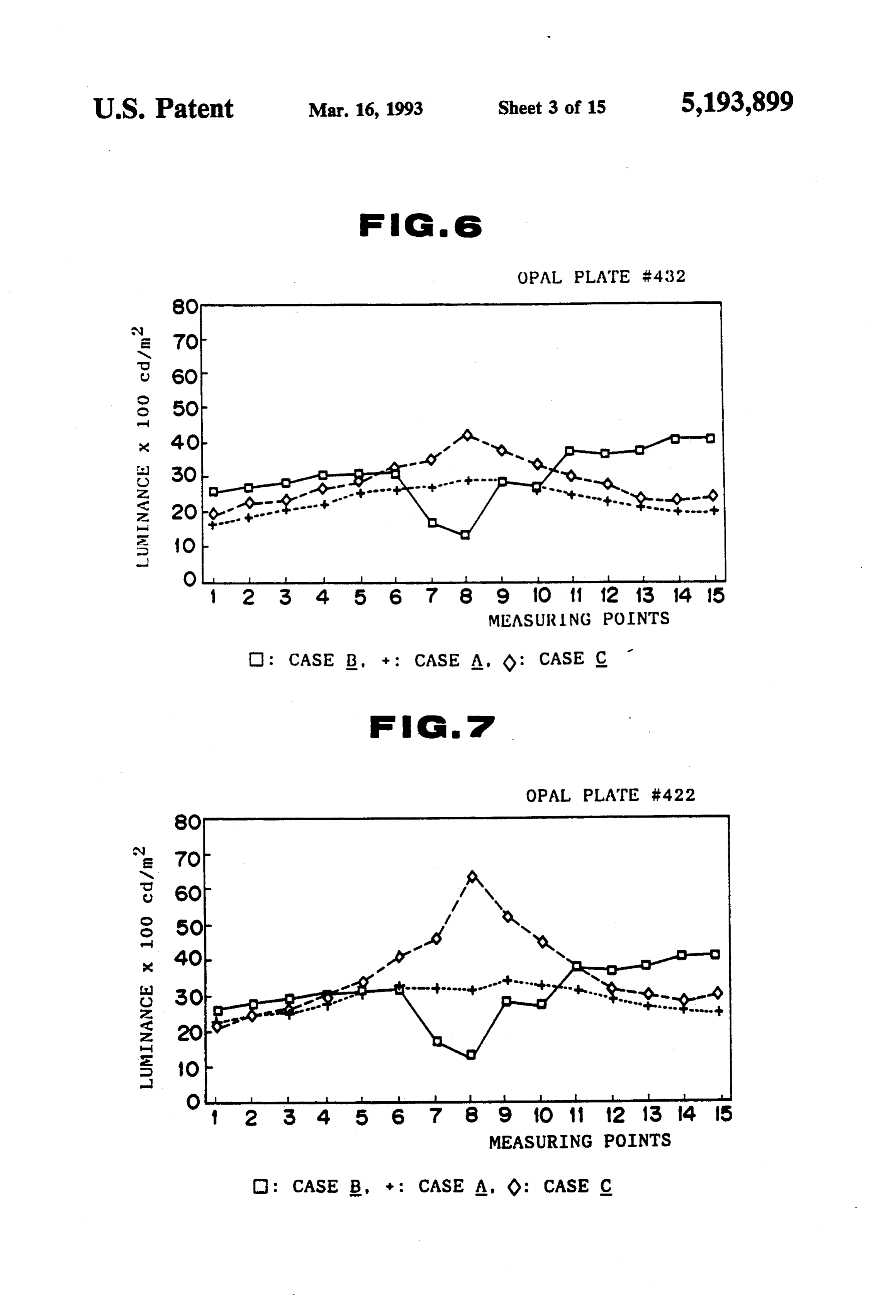
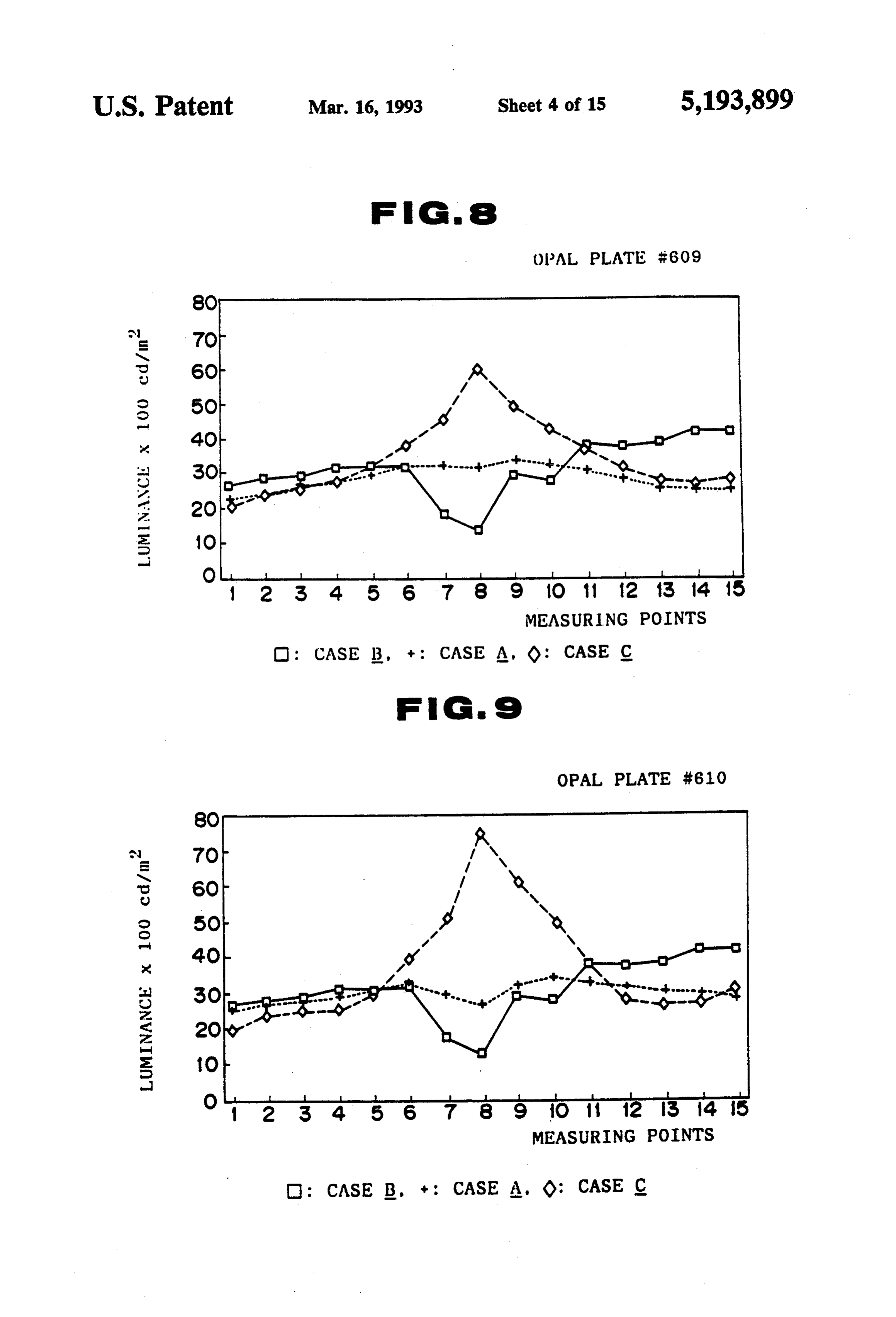
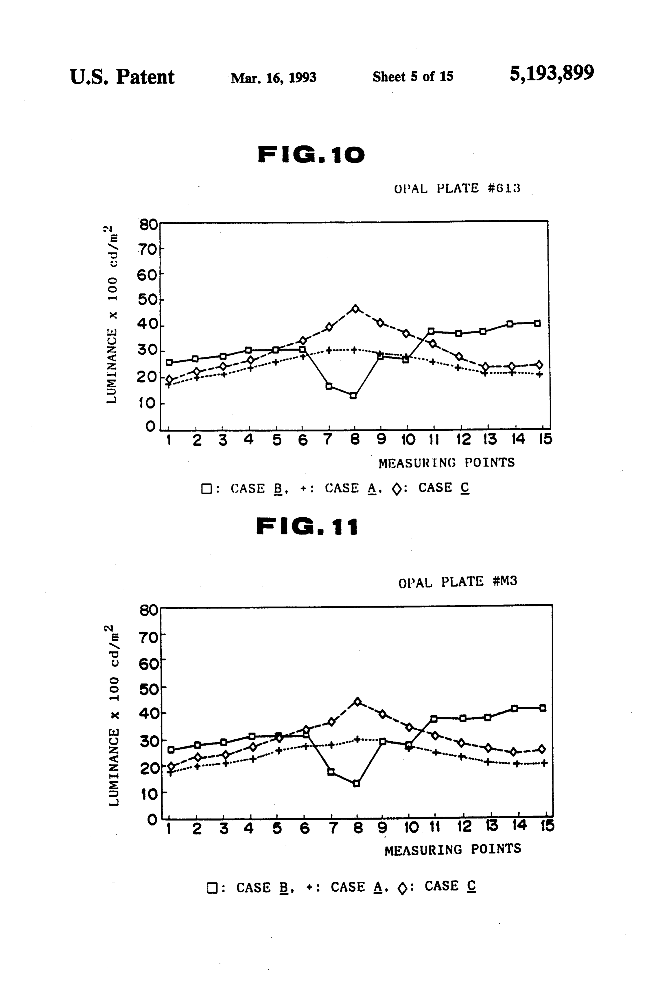
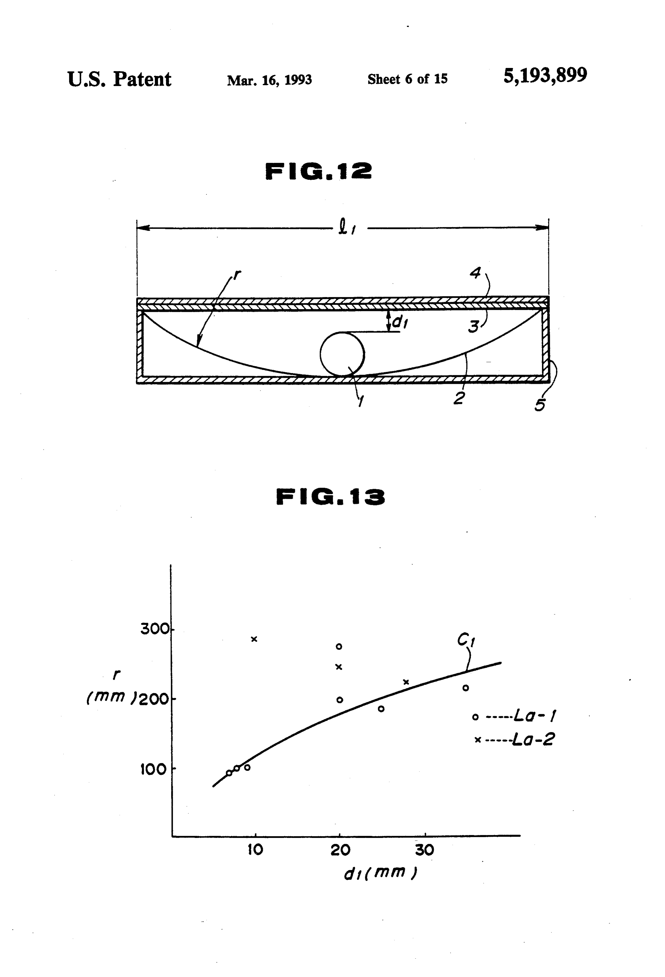
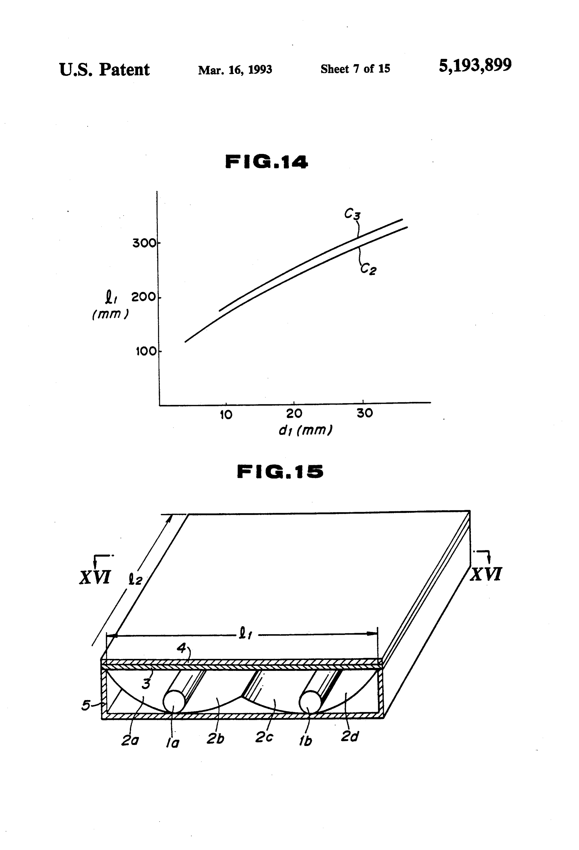
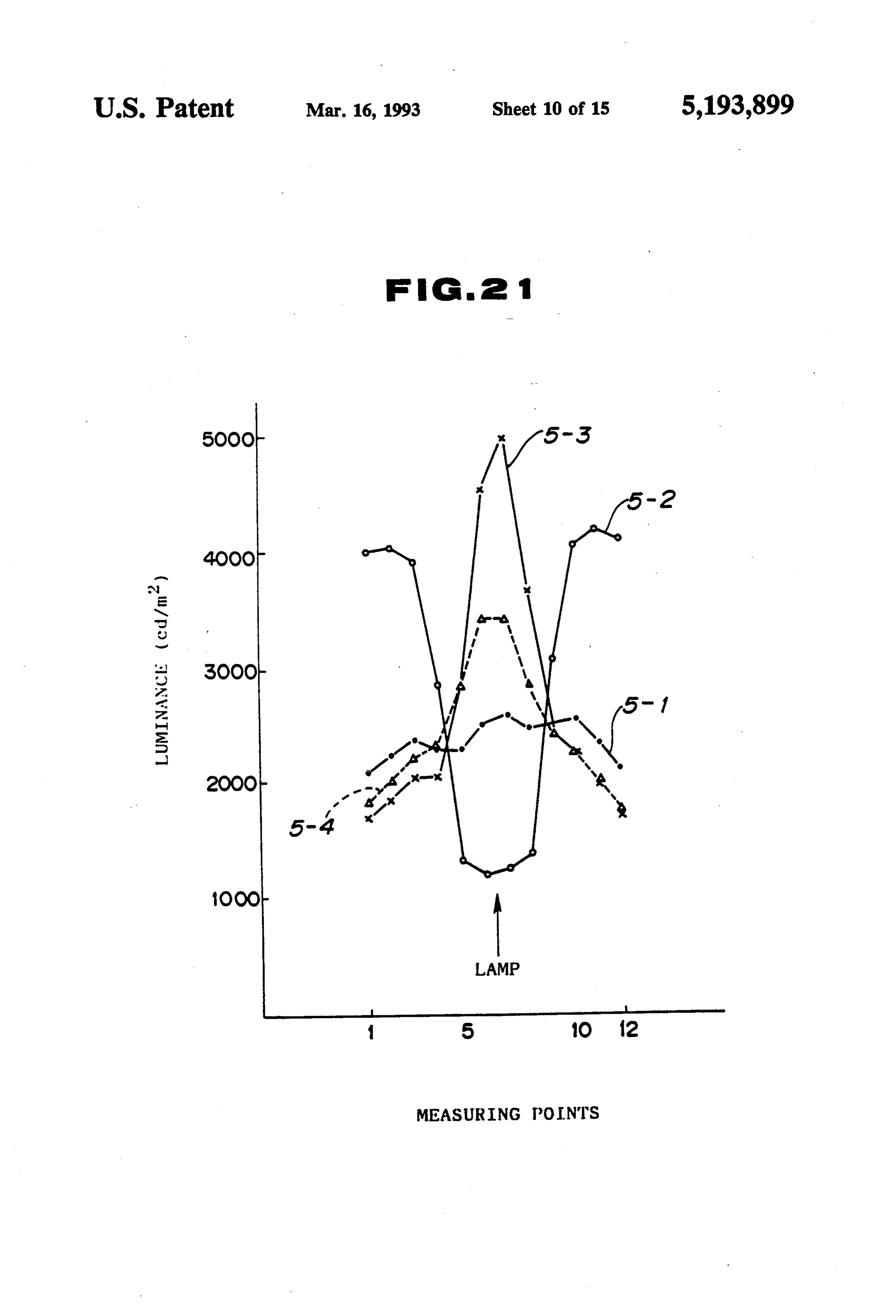
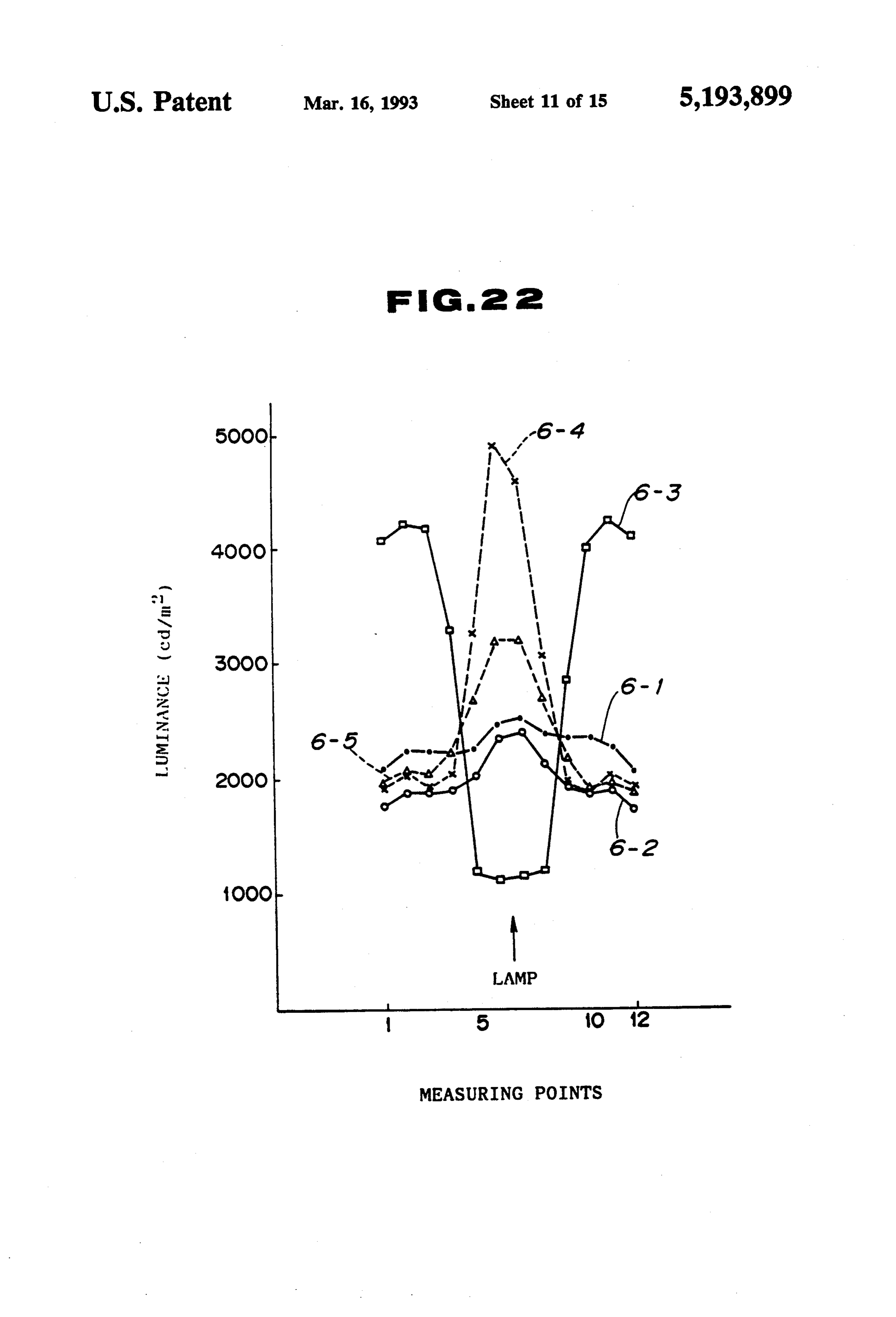
FIG. 1 is a perspective view showing an embodiment 35 reflecting surface 2 was an element in which a silver of the invention; vacuumde-position polyester filni having its thickness FIG. 2 is an enlarged cross-sectional view taken of 25 micorns was laminated onto a surface of an alumi along the line II-II in FIG. 1; num sheet having its thickness of 0.5 mm. The multi FIG. 3 is a fragmentary enlarged view of a multi prism sheet 3 used a colorless and transparent acrylic prism sheet; resinous plate (thickness: 1 mm), and was obtained such FIG. 4 is a fragmentary cross-sectional view of an that the acrylic resinous plate was heat-pressed together example which is used to consider a width of a stripe with a mold. As shown in FIG. 3, the multi-prism sheet like dark portion; 3 was used in which a group of prisms having generally FIG. 5 is a cross-sectional view of a light box which their configuration of regular triangle, whose pitch P is used to consider a configuration of a reflecting sur 45 was 0.38 mm, whose prism angle a1 and a2 were both face; 31.5' and whose head vertex angle a was 63', were FIGS. 6 through 11 are graphs evaluating perfor arranged so as to extend in parallel relation to each nance in the first embodiment of the invention; other. Further, the dark-portion removing sheet 4 used FIG. 12 is a cross-sectional view showing another various synthetic resinous translucent plates (thickness: embodiment of the invention; 2 mm and 1 mm), subsequently to be described. The FIGS. 13 and 14 are graphs showing a characteristic housing 5 was assembled into a box configuration by the of the embodiment illustrated in F.G. 12; use of a synthetic resinous plate. Dimensions of the FIG. 15 is a fragmentary cross-sectional perspective device at this time were such thatl was 150 mm which view showing a second embodiment of the invention; was six times the diameter of the fluorescent lamp, l. FIG. 16 is a cross-sectional view taken along the line 55 was 350mm, and a gap d between the fluorescent lamp XVI-XVI in FIG. 15; and an opening surface of the housing 5 was 5 mm. FIG. 17 is a graph evaluating performance in the second embodiment of the invention; (1) Measurement of Luminance Distribution as Light FIGS. 18 and 19 are cross-sectional views of other Box aspects of the second embodiment of the invention; 60 Of the devices constructed as described above, in FIG. 20 is a fragmentary cross-sectional perspective order to grasp the quantity of light of the housing pro view showing a third embodiment of the invention; vids: with the light source and the reflecting surface, FIGS. 21 and 22 are graphs evaluating performance the Saulti-prism sheet 3 and the dark-portion removing in the third embodiment; sheet 4 illustrated in FIG. 2 were first removed, and a FIG. 23 is a cross-sectional view showing another 65 colorless transparent acrylic resinous plate having its aspect of the third embodiment of the invention; thickness of 3 mm rested in place of the multi-prism FIG. 24 is a cross-sectional view showing an example sheet 3 and the dark-portion removing sheet 4, to form of an optical sheet which is used in the invention; a light box (hereafter the light box was used for conve
Page 19
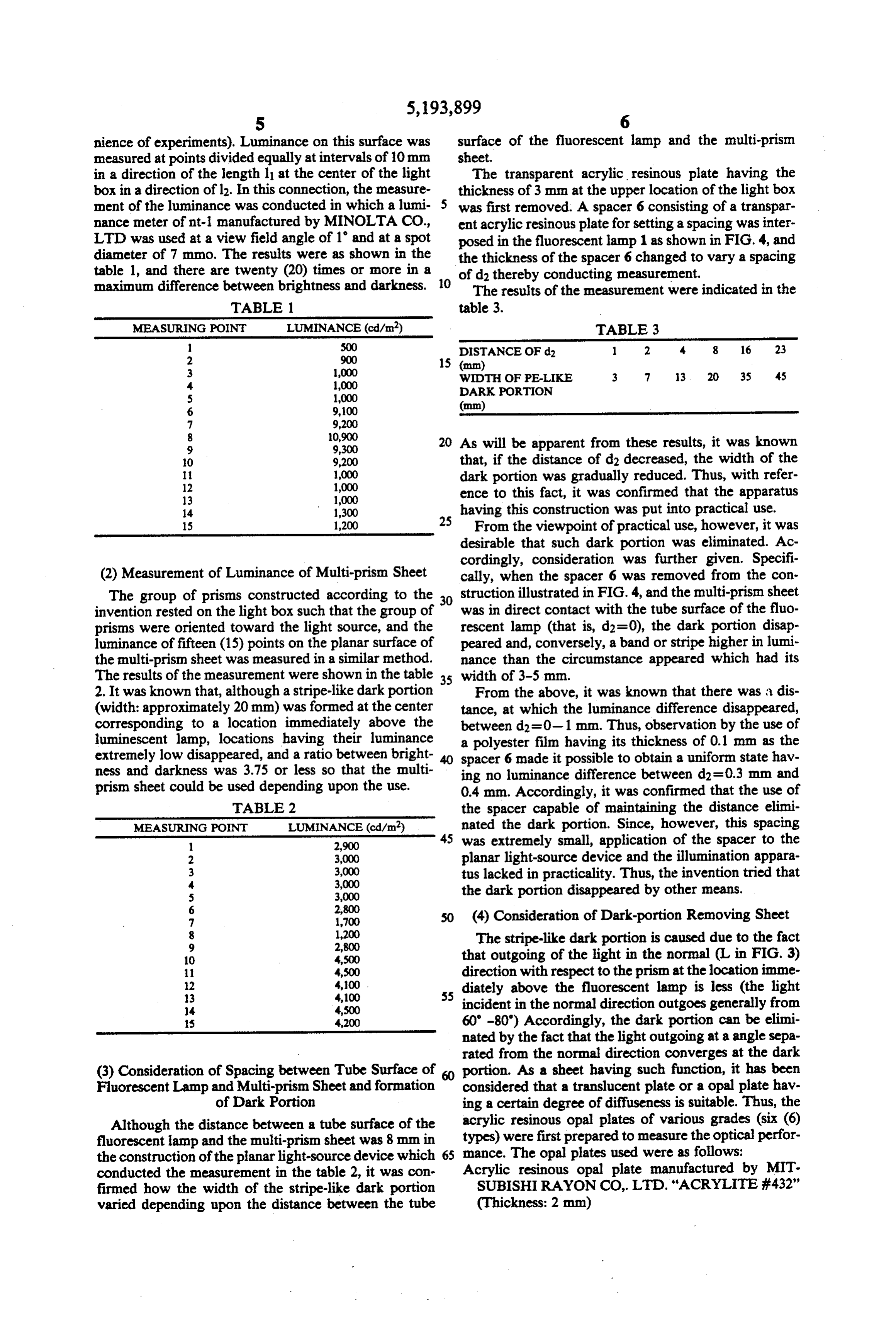
nience of experiments). Luminance on this surface was surface of the fluorescent lamp and the multi-prism measured at points divided equally at intervals of 10 mm sheet.
in a direction of the length l1 at the center of the light The transparent acrylic resinous plate having the box in a direction of 12. In this connection, the measure thickness of 3 mm at the upper location of the light box ment of the luminance was conducted in which a lumi- 5 was first removed. A spacer 6 consisting of a transpar nance meter of nit-1 manufactured by MINOLTA CO., ent acrylic resinous plate for setting a spacing was inter LTD was used at a view field angle of 1 and at a spot posed in the fluorescent lamp 1 as shown in FIG. 4, and diameter of 7 mmo. The results were as shown in the the thickness of the spacer 6 changed to vary a spacing table 1, and there are twenty (20) times or more in a of d2 thereby conducting measurement. maximum difference between brightness and darkness. 10 The results of the measurement were indicated in the
MEASURING POINT LUMINANCE (cd/m) TABLE 3 500 DISTANCE OF d2 1 2 4. 8 16 23
1,000 WDTH OF PE-LIKE 3 7 13 20 35 45
10,900 20 As will be apparent from these results, it was known
1. 9,200 that, if the distance of d2 decreased, the width of the 11 1,000 dark portion was gradually reduced. Thus, with refer 12 1,000 ence to this fact, it was confirmed that the apparatus
14 1,300 having this construction was put into practical use. 15 1,200 25 From the viewpoint of practical use, however, it was desirable that such dark portion was eliminated. Ac cordingly, consideration was further given. Specifi (2) Measurement of Luminance of Multi-prism Sheet cally, when the spacer 6 was removed from the con The group of prisms constructed according to the was struction illustrated in FIG.4, and the multi-prism sheet invention rested on the light box such that the group of in direct contact with the tube surface of the fluo prisms were oriented toward the light source, and the rescent lamp (that is, d2=0), the dark portion disap luminance of fifteen (15) points on the planar surface of peared and, conversely, a band or stripe higher in lumi the multi-prism sheet was measured in a similar method. nance than the circumstance appeared which had its The results of the measurement were shown in the table 35 width of 3-5 mm.
2. It was known that, although a stripe-like dark portion From the above, it was known that there was a dis (width: approximately 20 mm) was formed at the center tance, at which the luminance difference disappeared, corresponding to a location immediately above the between d2 = 0-1 mm. Thus, observation by the use of luminescent lamp, locations having their luminance a polyester film having its thickness of 0.1 mm as the extremely low disappeared, and a ratio between bright spacer 6 made it possible to obtain a uniform state hav ness and darkness was 3.75 or less so that the multi ing no luminance difference between d2=0.3 mm and prism sheet could be used depending upon the use. 0.4 mm. Accordingly, it was confirmed that the use of TABLE 2 the spacer capable of maintaining the distance elimi MEASURING POINT LUMINANCE (cd/m2) nated the dark portion. Since, however, this spacing 45 was extremely small, application of the spacer to the
3,000 planar light-source device and the illumination appara
tus lacked in practicality. Thus, the invention tried that 3,000 the dark portion disappeared by other means.
2,800 (4) Consideration of Dark-portion Removing Sheet
1,200 The stripe-like dark portion is caused due to the fact
4,500 that outgoing of the light in the normal (L in FIG. 3) 11 4,500 direction with respect to the prism at the location imme
diately above the fluorescent lamp is less (the light 14 4,500 incident in the normal direction outgoes generally from 15 4,200 60-80') Accordingly, the dark portion can be elimi nated by the fact that the light outgoing at a angle sepa rated from the normal direction converges at the dark (3) Consideration of Spacing between Tube Surface of portion. As a sheet having such function, it has been Fluorescent Lamp and Multi-prism Sheet and formation considered that a translucent plate or a opal plate hav of Dark Portion ing a certain degree of diffuseness is suitable. Thus, the Although the distance between a tube surface of the acrylic resinous opal plates of various grades (six (6) fluorescent lamp and the multi-prism sheet was 8 mm in types) were first prepared to measure the optical perfor the construction of the planar light-source device which mance. The opal plates used were as follows: conducted the measurement in the table 2, it was con Acrylic resinous opal plate manufactured by MIT firmed how the width of the stripe-like dark portion SUBISHI RAYON CO, LTD. "ACRYLITE #432" varied depending upon the distance between the tube (Thickness: 2 mm)
Page 20
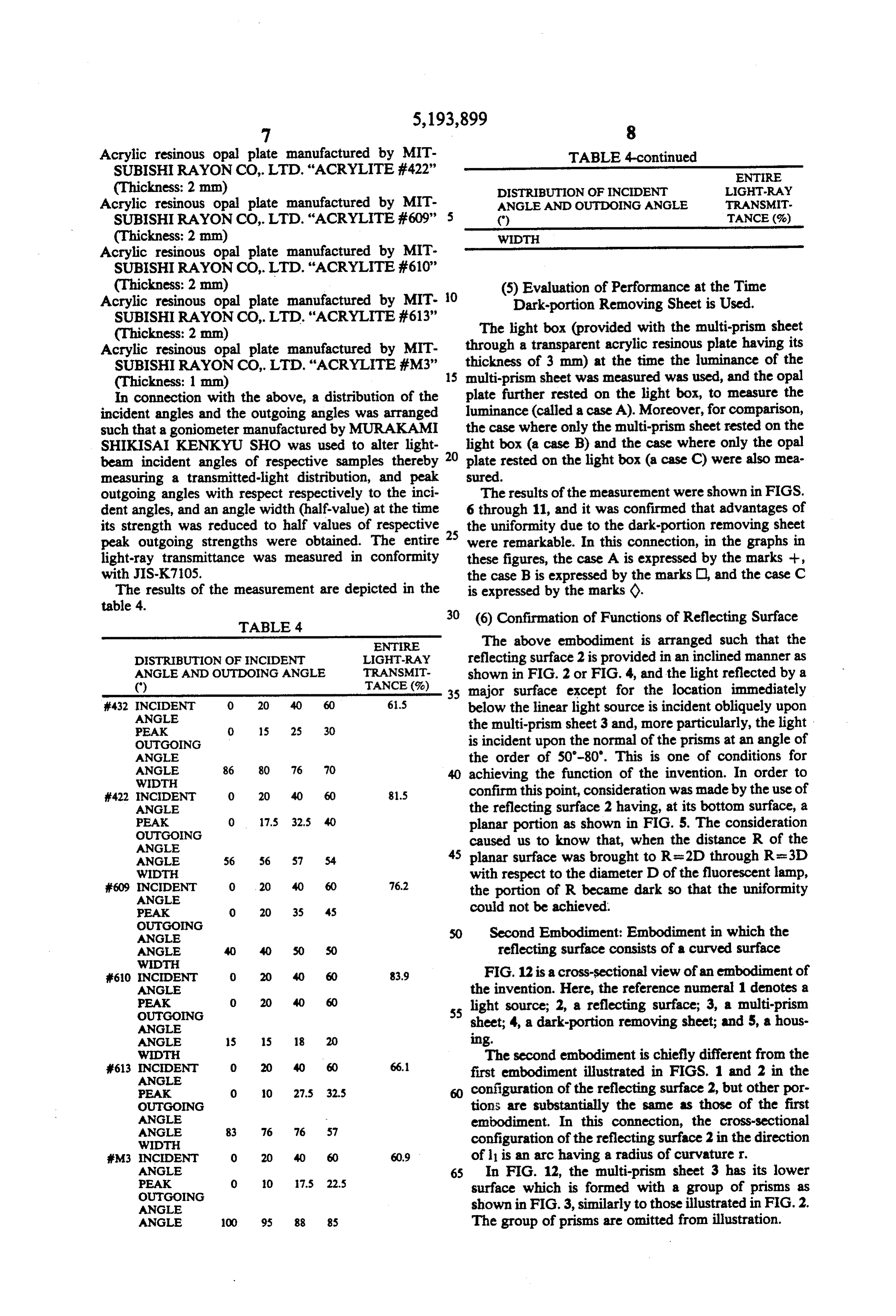
Acrylic resinous opal plate manufactured by MIT TABLE 4-continued SUBISHI RAYON CO, LTD. “ACRYLITE #422' ENTRE (Thickness: 2 mm) DISTRIBUTION OF INCIDENT LIGHT-RAY Acrylic resinous opal plate manufactured by MIT ANGLE AND OUTDONG ANGLE TRANSMIT. SUBISHI RAYON CO,LTD. “ACRYLITE #609' 5 () TANCE (%) (Thickness: 2 mm) WDTH
Acrylic resinous opal plate manufactured by MIT
SUBISHIRAYON CO.,LTD. "ACRYLITE #610"
(Thickness: 2 mm) (5) Evaluation of Performance at the Time Acrylic resinous opal plate manufactured by MIT O Dark-portion Removing Sheet is Used. SUBISHIRAYON CO,LTD. "ACRYLITE #613' The light box (provided with the multi-prism sheet (Thickness: 2 mm) through a transparent acrylic resinous plate having its Acrylic resinous opal plate manufactured by MIT
SUBISHI RAYON CO, LTD. “ACRYLITE #M3” 15 thickness of 3 mm) at the time the luminance of the (Thickness: 1 mm) multi-prism sheet was measured was used, and the opal In connection with the above, a distribution of the plate further rested on the light box, to measure the incident angles and the outgoing angles was arranged luminance (called a caseA). Moreover, for comparison, such that a goniometer manufactured by MURAKAMI the case where only the multi-prism sheet rested on the SHIKISAI KENKYU SHO was used to alter light light box (a case B) and the case where only the opal beam incident angles of respective samples thereby 20 plate rested on the light box (a case C) were also mea measuring a transmitted-light distribution, and peak sured.
outgoing angles with respect respectively to the inci The results of the measurement were shown in FIGS. dent angles, and an angle width (half-value) at the time 6 through 11, and it was confirmed that advantages of its strength was reduced to half values of respective 25 the uniformity due to the dark-portion removing sheet peak outgoing strengths were obtained. The entire were remarkable. In this connection, in the graphs in light-ray transmittance was measured in conformity these figures, the case A is expressed by the marks --, with JIS-K7105. the case B is expressed by the marks, and the case C The results of the measurement are depicted in the is expressed by the marks ().
table 4. 30 (6) Confirmation of Functions of Reflecting Surface
TABLE 4
ENTRE The above embodiment is arranged such that the
DESTRIBUTION OF INCIDENT LIGHT-RAY reflecting surface 2 is provided in an inclined manner as
ANGLE AND OUTDONG ANGLE TRANSMIT
TANCE (%)
shown in FIG. 2 or FIG. 4, and the light reflected by a () major surface except for the location immediately
432 INCIDENT
ANGLE
O 20 40 60 65 below the linear light source is incident obliquely upon PEAK 0. 15 2S 30 the multi-prism sheet 3 and, more particularly, the light OUTGOING is incident upon the normal of the prisms at an angle of ANGLE the order of 50-80'. This is one of conditions for ANGLE 86 80 76 70 achieving the function of the invention. In order to
WDTH
422 NCIDENT 0 20 40 60 815 confirm this point, consideration was made by the use of ANGLE the reflecting surface 2 having, at its bottom surface, a
PEAK
OUTGOING
0 17.5 32.5 planar portion as shown in FIG. 5. The consideration ANGLE caused us to know that, when the distance R of the ANGLE 56 57 54 45 planar surface was brought to R=2D through R=3D WDTH with respect to the diameter D of the fluorescent lamp, F609 NCIDENT O 20 76.2 the portion of R became dark so that the uniformity
ANGLE
PEAK O 20 35 45 could not be achieved.
OUTGOING
ANGLE Second Embodiment: Embodiment in which the ANGLE 40 50 SO reflecting surface consists of a curved surface
WOTH
610 NCOENT 0. 20 40 60 83.9 F.G. 12 is a cross-sectional view of an embodiment of ANGLE the invention. Here, the reference numeral 1 denotes a 55 light source; 2, a reflecting surface; 3, a multi-prism
OUTGONG sheet; 4, a dark-portion removing sheet; and 5, a hous
ANGLE
ANGLE 15 18 ling.
WOTH
The second embodiment is chiefly different from the
ANGLE
first embodiment illustrated in FIGS. 1 and 2 in the
PEAK O 10 27.5 325 configuration of the reflecting surface 2, but other por OUTGONG tions are substantially the same as those of the first ANGLE embodiment. In this connection, the cross-sectional
WIDTH configuration of the reflecting surface 2 in the direction M3 NCOENT O 60.9 of li is an arc having a radius of curvaturer.
ANGLE
65 In FIG. 12, the multi-prism sheet 3 has its lower
OUGOING surface which is formed with a group of prisms as ANGLE shown in FIG.3, similarly to those illustrated in FIG.2. ANGLE 100 95 88 85 The group of prisms are omitted from illustration.
Page 21
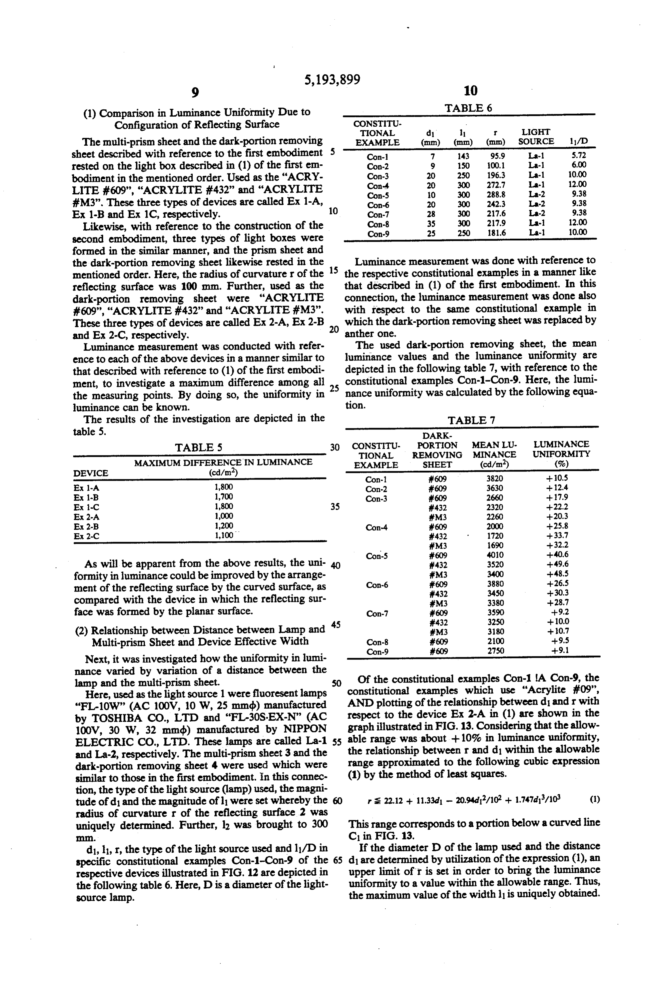
(1) Comparison in Luminance Uniformity Due to TABLE 6
Configuration of Reflecting Surface CONSTITU
The multi-prism sheet and the dark-portion removing EXAMPLE (mm) (mm) (mm) SOURCE 1 1/D sheet described with reference to the first embodiment 5 Con- 7 143 95.9 La-1 5.72 rested on the light box described in (1) of the first em Con-2
bodiment in the mentioned order. Used as the "ACRY Con-4 20 300 272.7 La- 12.00 LITE #609”, “ACRYLITE #432” and “ACRYLITE Con-5 O 300 288.8 La-2 9.38 #M3”. These three types of devices are called Ex 1-A, 10 Con-6 20 300 242.3 La-2 9.38 Ex 1-B and Ex 1C, respectively. Con-8
Likewise, with reference to the construction of the Con-9 25 250 8.6 La-l 10.00 second embodiment, three types of light boxes were formed in the similar manner, and the prism sheet and the dark-portion removing sheet likewise rested in the 15 Luminance measurement was done with reference to mentioned order. Here, the radius of curvaturer of the the respective constitutional examples in a manner like reflecting surface was 100 mm. Further, used as the that described in (1) of the first embodiment. In this dark-portion removing sheet were "ACRYLITE connection, the luminance measurement was done also #609', 'ACRYLITE #432' and “ACRYLITE #M3”. with respect to the same constitutional example in
These three types of devices are called Ex 2-A, Ex 2-B 20 which the dark-portion removing sheet was replaced by and Ex 2-C, respectively. anther one.
Luminance measurement was conducted with refer The used dark-portion removing sheet, the mean ence to each of the above devices in a manner similar to luminance values and the luminance uniformity are that described with reference to (1) of the first embodi depicted in the following table 7, with reference to the ment, to investigate a maximum difference among all constitutional examples Con-1-Con-9. Here, the lumi the measuring points. By doing so, the uniformity in 25 nance uniformity was calculated by the following equa luminance can be known. tion.
The results of the investigation are depicted in the TABLE 7 table 5. DARK
TABLE 5 30 CONSTITU- PORTION MEAN LU. LUMINANCE
TIONAL REMOVING MINANCE UNIFORMITY
MAXIMUM DIFFERENCENLUMINANCE EXAMPLE SHEET (cd/m2) (%) DEVICE (cd/m2) Con-1 #609 3820 -- 0.5 Ex 1-A 1,800 Con-2 609 3630 -- 12.4 Ex 1-B 1,700 Con-3 609 2660 --17.9 Ex-C 1,800 35 #432 2320 --22.2 Ex2-A 1,000 iFM3 2260 20.3 Ex 2-8 1,200 Con-4 609 2000 --25.8 Ex2-C 1,100 432 1720 --33.7
As will be apparent from the above results, the uni- 40 432 3520 - 49.6 formity in luminance could be improved by the arrange Con-6
ment of the reflecting surface by the curved surface, as 432 3450 --30.3 compared with the device in which the reflecting sur M3 3380 --28.7 face was formed by the planar surface. Con-7 #609 3590 --9.2 45 432 3250 - 10.0 (2) Relationship between Distance between Lamp and FM3 3180 -- 0.7 Multi-prism Sheet and Device Effective Width Con-8
Next, it was investigated how the uniformity in lumi nance varied by variation of a distance between the lamp and the multi-prism sheet. SO Of the constitutional examples Con-1. A Con-9, the Here, used as the light source 1 were fluoresent lamps constitutional examples which use "Acrylite #09', "FL-10W' (AC 100V, 10 W, 25 mmdb) manufactured AND plotting of the relationship between d1 and r with by TOSHIBA CO., LTD and "FL-30S-EX-N” (AC respect to the device Ex 2-A in (1) are shown in the 100V, 30 W, 32 mmdb) manufactured by NIPPON graphrange illustrated in FIG. 13. Considering that the allow ELECTRIC CO.,LTD. These lamps are called La-1 55 able the was about +10% in luminance uniformity, relationship between r and d1 within the allowable and La-2, respectively. The multi-prism sheet 3 and the dark-portion removing sheet 4 were used which were range approximated to the following cubic expression similar to those in the first embodiment. In this connec (1) by the method of least squares.
tion, the type of the light source (lamp) used, the magni tude of d1 and the magnitude of li were set whereby the rs 22.12 + 11.33d - 20.94d/10' + 1.747di/10 (1) radius of curvature r of the reflecting surface 2 was uniquely determined. Further, 12 was brought to 300 This range corresponds to a portion below a curved line . C1 in FIG. 13.
dl, l, r, the type of the light source used and lydin If the diameter D of the lamp used and the distance specific constitutional examples Con-1-Con-9 of the 65 d1 are determined by utilization of the expression (1), an respective devices illustrated in FIG. 12 are depicted in upper limit of r is set in order to bring the luminance the following table 6. Here, D is a diameter of the light uniformity to a value within the allowable range. Thus, source lamp. the maximum value of the width l is uniquely obtained.
Page 22
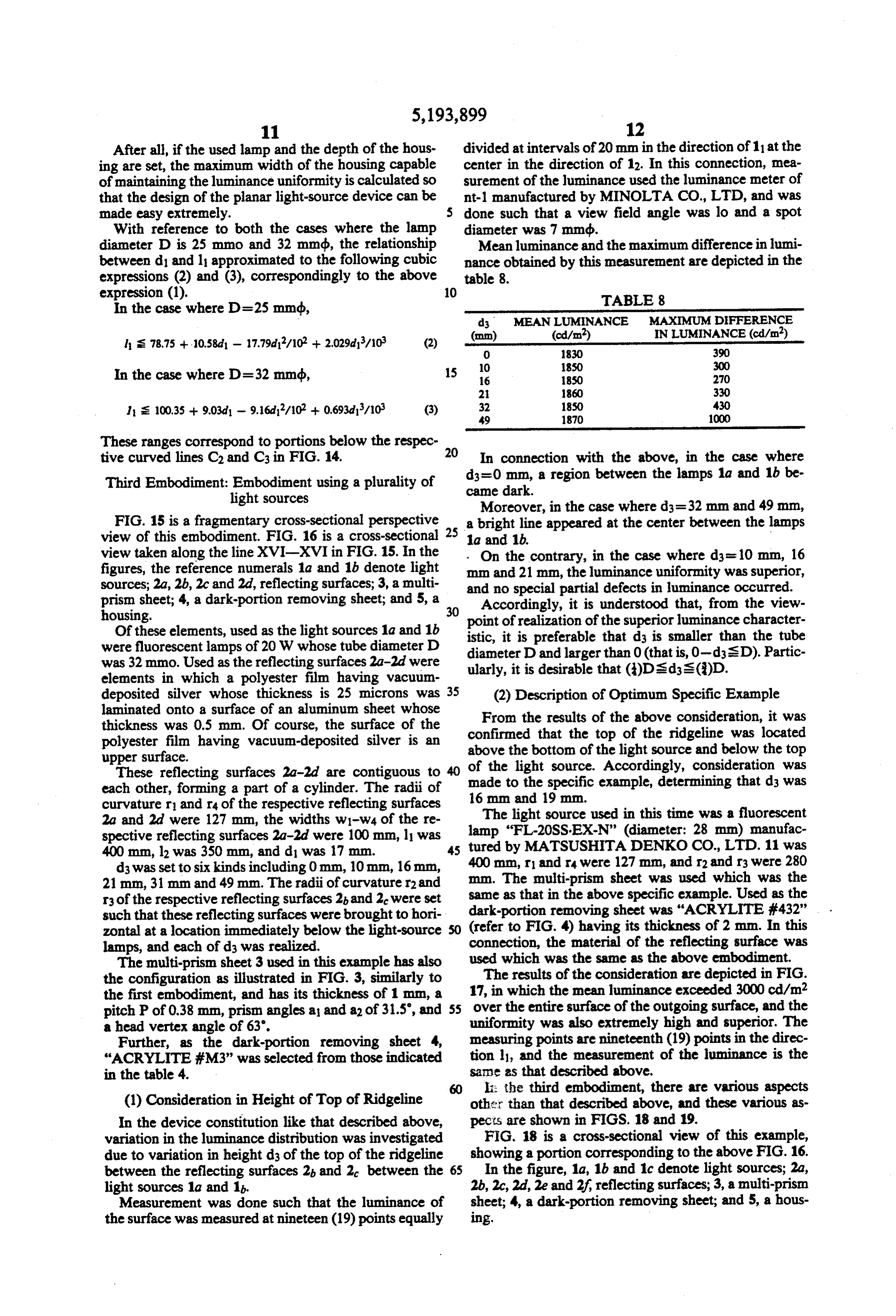
After all, if the used lamp and the depth of the hous divided at intervals of 20 mm in the direction of 11 at the ing are set, the maximum width of the housing capable center in the direction of 12. In this connection, mea of maintaining the luminance uniformity is calculated so surement of the luminance used the luminance meter of that the design of the planar light-source device can be int-1 manufactured by MINOLTA CO.,LTD, and was made easy extremely. done such that a view field angle was lo and a spot With reference to both the cases where the lamp diameter was 7 mmdb.
diameter D is 25 mmo and 32 mmdb, the relationship Mean luminance and the maximum difference in lumi between d1 and l approximated to the following cubic nance obtained by this measurement are depicted in the expressions (2) and (3), correspondingly to the above table 8.
TABLE 8
In the case where D=2.5 mmdb, d3 MEAN LUMINANCE MAXIMUM DIFFERENCE
ls 78.75 + 10.58d - 17.79d/102 + 2.029d/10 (2) 0. 1830 390
In the case where D=32 mmdb, 16 1850 270
1 s 100.35 + 903d - 9.16d17/102 + 0.693d/10 (3) 32 1850 430
These ranges correspond to portions below the respec 20 tive curved lines C2 and C3 in FIG. 14. In connection with the above, in the case where Third Embodiment: Embodiment using a plurality of came dark. d3=0 mm, a region between the lamps 1a and 1b be light sources Moreover, in the case where d=32 mm and 49 mm,
FIG. 15 is a fragmentary cross-sectional perspective 25 a bright line appeared at the center between the lamps view of this embodiment. FIG. 16 is a cross-sectional 1a and 1b.
view taken along the line XVI-XVI in FIG. 15. In the . On the contrary, in the case where ds= 10 mm, 16 figures, the reference numerals 1a and 1b denote light mm and 21 mm, the luminance uniformity was superior, sources; 2a, 2b, 2c and 2d, reflecting surfaces; 3, a multi and no special partial defects in luminance occurred. prism sheet; 4, a dark-portion removing sheet; and 5, a housing. 30 Accordingly, it is understood that, from the view point of realization of the superior luminance character
Of these elements, used as the light sources 1a and 1b istic, it is preferable that ds is smaller than the tube were fluorescent lamps of 20W whose tube diameter D diameter D and larger than 0 (that is, 0-disD). Partic was 32mmo. Used as the reflecting surfaces 2a-2d were ularly, it is desirable that ()Dsd3s()D. elements in which a polyester film having vacuum deposited silver whose thickness is 25 microns was 35 (2) Description of Optimum Specific Example laminated onto a surface of an aluminum sheet whose thickness was 0.5 mm. Of course, the surface of the From the results of the above consideration, it was polyester film having vacuum-deposited silver is an confirmed that the top of the ridgeline was located above the bottom of the light source and below the top upper surface.
These reflecting surfaces 2a-2d are contiguous to 40 of thetolight source. Accordingly, consideration was each other, forming a part of a cylinder. The radii of made the specific example, determining that ds was curvature r1 and ra of the respective reflecting surfaces 16 mm and 19 mm.
2a and 2d were 127 mm, the widths wi-ws of the re The light source used in this time was a fluorescent spective reflecting surfaces 2a-2d were 100 mm, 11 was lamp "FL-20SS-EX-N" (diameter: 28 mm) manufac 400 mm, lz was 350 mm, and d1 was 17 mm. 45 tured by MATSUSHITA DENKO CO.,LTD. 11 was d3 was set to six kinds including 0 mm, 10mm, 16mm, 400 mm, r1 and r were 127 mm, and r2 and r3 were 280 21 mm, 31 mm and 49 mm. The radii of curvature r2 and mm. The multi-prism sheet was used which was the r3 of the respective reflecting surfaces 2 and 2 were set same as that in the above specific example. Used as the such that these reflecting surfaces were brought to hori dark-portion removing sheet was "ACRYLITE #432" zontal at a location immediately below the light-source (refer to FIG. 4) having its thickness of 2 mm. In this lamps, and each of ds was realized. connection, the material of the reflecting surface was The multi-prism sheet 3 used in this example has also used which was the same as the above embodiment. the configuration as illustrated in FIG. 3, similarly to The results of the consideration are depicted in FIG. the first embodiment, and has its thickness of 1 mm, a 17, in which the mean luminance exceeded 3000 cd/m2 pitch P of 0.38 mm, prism angles a and a2 of 31.5', and 55 over the entire surface of the outgoing surface, and the a head vertex angle of 63. uniformity was also extremely high and superior. The Further, as the dark-portion removing sheet 4, measuring points are nineteenth (19) points in the direc "ACRYLITE #M3” was selected from those indicated tion l, and the measurement of the luminance is the in the table 4. same as that described above. li: the third embodiment, there are various aspects (1) Consideration in Height of Top of Ridgeline other than that described above, and these various as In the device constitution like that described above, pects are shown in FIGS. 18 and 19. variation in the luminance distribution was investigated FIG. 18 is a cross-sectional view of this example, due to variation in height ds of the top of the ridgeline showing a portion corresponding to the above FIG. 16. between the reflecting surfaces 2 and 2 between the 65 In the figure, 1a, 1b and 1c denote light sources; 2a, light sources 1a and 1b. 2b, 2c, 2d, 2e and 2f, reflecting surfaces; 3, a multi-prism Measurement was done such that the luminance of sheet; 4, a dark-portion removing sheet; and 5, a hous the surface was measured at nineteen (19) points equally 1ng.
Page 23
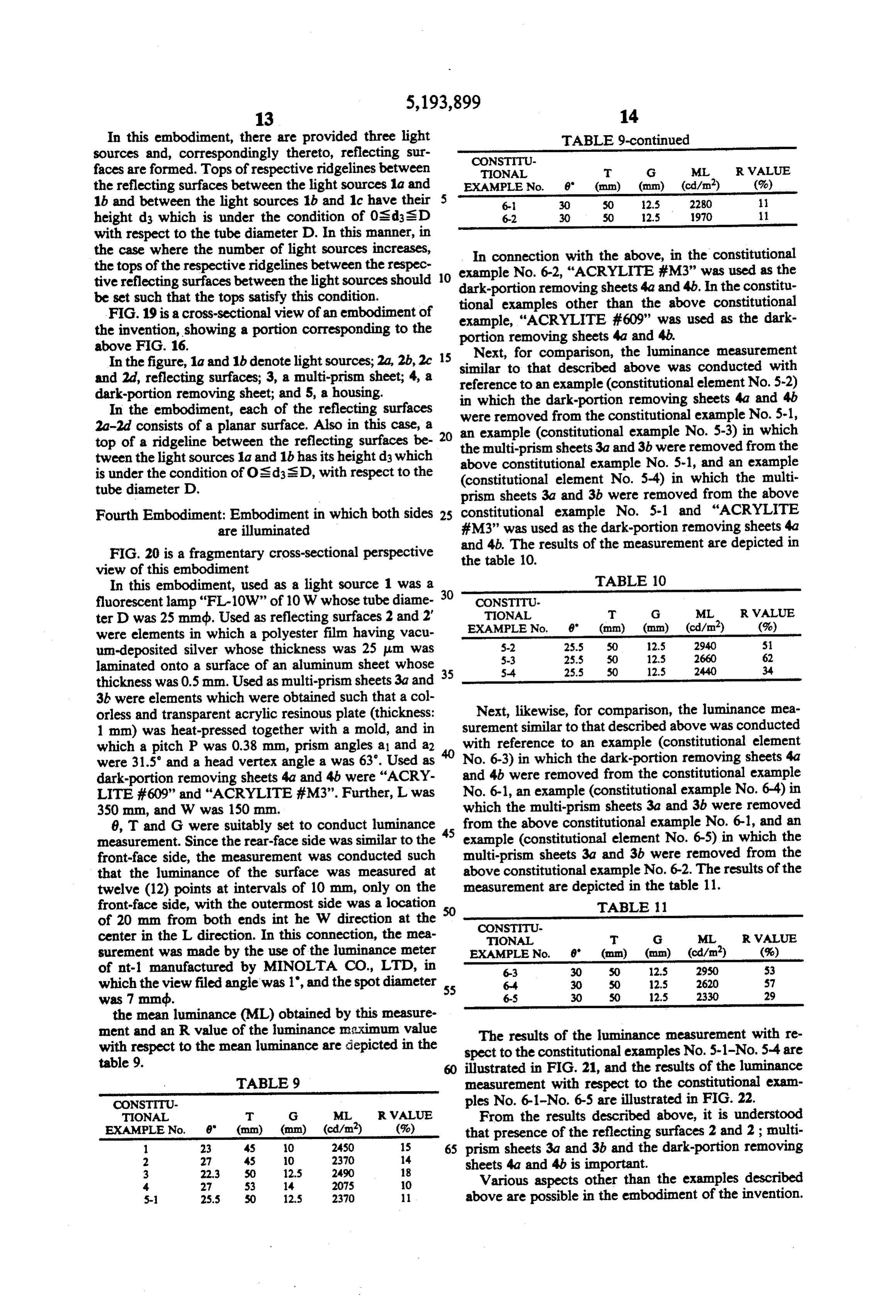
In this embodiment, there are provided three light TABLE 9-continued Sources and, correspondingly thereto, reflecting sur CONSTITU faces are formed. Tops of respective ridgelines between TIONAL T G ML RVALUE the reflecting surfaces between the light sources 1a and 5 EXAMPLE No. 8" (mm) (mm) (cd/m) (%) 1b and between the light sources 1b and 1c have their 6-1 30 50 12.S 2280 height ds which is under the condition of 0s dsD 6-2 30 50 2.5 1970 1 with respect to the tube diameter D. In this manner, in the case where the number of light sources increases, In connection with the above, in the constitutional the tops of the respective ridgelines between the respec example No. 6-2, "ACRYLITE #M3” was used as the
tive reflecting surfaces between the light sources should dark-portion be set such that the tops satisfy this condition. removing sheets 4a and 4b. In the constitu tional examples
FIG. 19 is a cross-sectional view of an embodiment of example, "ACRYLITE other than the above constitutional the invention, showing a portion corresponding to the portion removing sheets #609” 4a and was used as the dark
above FIG. 16. Next, for comparison, the luminance measurement
In the figure, 1a and 1b denote light sources; 2a, 2b, 2c similar to that described above was conducted and 2d, reflecting surfaces; 3, a multi-prism sheet; 4, a reference to an example (constitutional element No.with 5-2) dark-portion removing sheet; and 5, a housing. in which the dark-portion removing sheets 4a and 4b In the embodiment, each of the reflecting surfaces were removed from the constitutional example No. 5-1, 2a-2d consists of a planar surface. Also in this case, a 20 an example (constitutional example No. 5-3) in which top of a ridgeline between the reflecting surfaces be the multi-prism sheets 3a and 3b were removed from the tween the light sources 1a and 1b has its height d which above constitutional example No. 5-1, and an example is under the condition of OsdsD, with respect to the (constitutional element No. 5-4) in which the multi tube diameter D. prism sheets 3a and 3b were removed from the above Fourth Embodiment: Embodiment in which both sides 25 constitutional example No. 5-1 and "ACRYLITE are illuminated #M3” was used as the dark-portion removing sheets 4a FIG. 20 is a fragmentary cross-sectional perspective and 4b. The results of the measurement are depicted in the table 10.
view of this embodiment
In this embodiment, used as a light source 1 was a TABLE 10 fluorescent lamp"FL-10W" of 10W whose tube diame 30 CONSTITU TIONAL T G ML R VALUE ter D was 25 mmdb. Used as reflecting surfaces 2 and 2' EXAMPLE No. 8" (mm) (mm) (cd/m) (%) were elements in which a polyester film having vacu S-2 25.5 50 2.5 2940 5 un-deposited silver whose thickness was 25 um was 5-3 25.5 50 12.5 2660 62 laminated onto a surface of an aluminum sheet whose 5-4 25.5 50 12.5 2440 34 thickness was 0.5mm. Used as multi-prism sheets 3a and 35 3b were elements which were obtained such that a col orless and transparent acrylic resinous plate (thickness: Next, likewise, for comparison, the luminance mea 1 mm) was heat-pressed together with a mold, and in surement similar to that described above was conducted which a pitch P was 0.38 mm, prism angles a1 and a2 with reference to an example (constitutional element were 31.5' and a head vertex angle a was 63. Used as No. 6-3) in which the dark-portion removing sheets 4a dark-portion removing sheets 4a and 4b were "ACRY and 4b were removed from the constitutional example LITE #609" and "ACRYLITE #M3”. Further, L was No. 6-1, an example (constitutional example No. 64) in 350 mm, and W was 150 mm. which the multi-prism sheets 3a and 3b were removed 8, T and G were suitably set to conduct luminance from the above constitutional example No. 6-1, and an measurement. Since the rear-face side was similar to the 45 example (constitutional element No. 6-5) in which the front-face side, the measurement was conducted such multi-prism sheets 3a and 3b were removed from the that the luminance of the surface was measured at above constitutional example No. 6-2. The results of the twelve (12) points at intervals of 10 mm, only on the measurement are depicted in the table 11. front-face side, with the outermost side was a location TABLE 1. of 20 mm from both ends int he W direction at the SO CONSTITU center in the L direction. In this connection, the nea TONAL T G ML R VALUE surement was made by the use of the luminance meter EXAMPLE No. 6' (mm) (mm) (cd/m) (%) of nt-1 manufactured by MINOLTA CO., LTD, in 6-3 30 SO 12.S 2950 53 which the view filed angle was 1", and the spot diameter 55 6-4 30 SO 12S 57 2620 was 7 mmdb. 6-5 30 S0 12.529 2330 the mean luminance (ML) obtained by this measure ment and an R value of the luminance maximum value The results of the luminance measurement with re with respect to the mean luminance are depicted in the spect to the constitutional examples No. 5-1-No. 5-4 are table 9. illustrated in FIG. 21, and the results of the luminance TABLE 9 measurement with respect to the constitutional exam
CONSTITU ples No. 6-1-No. 6-5 are illustrated in FIG. 22.
TIONAL T G ML RVALUE From the results described above, it is understood EXAMPLE No. 8" (mm) (mm) (cd/m2) (%) that presence of the reflecting surfaces 2 and 2; multi 1 23 4S 10 2450 15 65 prism sheets 3a and 3b and the dark-portion removing 2 27 4S 0 2370 14 sheets 4a and 4b is important.
4. 27 S3 14 2075 O Various aspects other than the examples described 5- 25.5 SO 12.5 2370 11 above are possible in the embodiment of the invention.
Page 24
FIG. 23 is a cross-sectional view showing an exam nation apparatuses, will next be described with refer ple. In the figure, components similar to these illustrated ence to the drawings.
in FIG. 20 are designated by the same reference numer FIG. 26 is an example of a guidance lamp which is so als. used as to be mounted to an emergency exit or the like. This example differs from the example illustrated in The guidance lamp has its front face which is provided FIG. 20 in the configuration of a pair of reflecting sur with a display 7 indicating guidance In this connection, faces 2 and 2', and the front-face-side portion and the the cross-section except for the display (generally, a rear-face-side portion are formed into their respective printed plastic sheet) is substantially the same as that configurations in which they have curved surfaces con illustrated in FIG. 2 The guidance lamp is uniform and cave toward a multi-prism sheet 3a or 3b. O bright, and it is possible to thin the housing 5. As de The description has been made above in detail in scribed same as previously, this example is substantially the the cross-section illustrated in FIG. 2 and, ac accordance with the embodiments. However, the con tents of the invention should not be limited to these cordingly, description will be made quoting this. The examples, but various modifications can be made to the 15 housing designated by the reference numeral 5 serves invention. For instance, the light source of the inven multi-prismhousing also as a for the illumination apparatus. The tion may use, other than the linear light source such as sheet 4 are arranged3 onandthethe sheet side dark-portion removing of the front face of the the fluorescent lamp, light sources which are arranged housing 5, and the reflecting surface linearly such as an LED array, a link lamp, a quenching . the side opposite to the light source 21. isThe provided on display 7 lamp or the like. 20 illustrated in FIG. 26 is provided further on the side of The reflecting surface 2 can also select a suitable metallic reflecting surface or the like. If the reflecting theInfront face of the multi-prism sheet 3. connection with the above, when the length of the surface has such function that a light from the light illumination apparatus in the 12 direction increases to source is reflected to make a major light obliquely inci enlarge the area, it is preferable dent upon the multi-prism sheet 3, the reflecting surface 25 source source device illustrated inthat the planar light
does not care about its configuration such as, for exam incorporated in the illumination apparatus. Further, ple, a surface which is composed of any combination of when planar surfaces having an upwardly concave surface, or sides, itdisplays is are provided respectively on the both preferable that the planar light-source device the like. illustrated in FIG. 20 or FIG. 23 is incorporated in the As the multi-prism sheet 3 employed in the invention, illumination apparatus. The illumination apparatus it is possible to use, other than the acrylic resin, syn shown in this figure is not limited to such guidance thetic resin such as polycarbonate resin, styrene resin, lamp, but is widely applicable to a display device for vinyl chloride resin or the like, or inorganic glass. As illuminating form its internal part. It is needless to say the multi-prism sheet 3, it is possible to use not only an that other displays are mounted whereby a display ill element like a plate (thickness: of the order of 0.5-5 35 lumination apparatus for various uses can be used, in mm), but also a film-like element thinner than the plate which, if an advertisement display is mounted to the like element. Further, the configuration of the prism illumination apparatus, an advertisement lamp can be should also be such that the direct light from the linear formed, in which, if a time display for trains is mounted light source or a light once reflected and incident from to the illumination apparatus, a time display lamp can be an oblique direction is concentrated in a direction per formed and, furthermore, in which, if a part of an elon pendicular to the multi-prism sheet 3 or in an optional gated destination display sheet is in contact with a dis direction to set the prism angle in accordance with the play surface, a destination displayboard for buses, trains direction in which the light outgoes. In this connection, or the like can be formed, or the like. the surface in which the group of prisms are not formed FIG. 27 shows an illumination apparatus for a liquid may be a fine roughened surface such as a mat-finishing 45 crystal display applied to the planar light-source device surface or the like. according to the invention. In the figure, the reference In connection with the above, in the case where a thin numeral 8 denotes a planar light-source device which is plate or a film is used as the multi-prism sheet 3 or the identical in constitution with the above-described pla dark-portion removing sheet 4 and in case of necessity, nar light-source device. Aliquid-crystal display element a transparent plate for prevention of deflection may be 9 rests on an illumination surface of the planar light interposed between the multi-prism sheet 3 and the light source device.
source 1. This liquid-crystal display device is arranged such Moreover, as the multi-prism sheet 3 and the dark that the light source 1 of the planar light-source device portion removing sheet 4 of the invention, it is also 8 is turned on to outgo a light toward the liquid-crystal possible to use an element in which the multi-prism 55 element 9 from the front face of the multi-prism sheet 3 sheet and the dark-portion removing sheet are bonded thereby applying an image signal voltage to a location together and united as shown, for example, in FIG. 24 between a pair of internal electrodes 15 and 16 of the at manufacture of the multi-prism sheet 3 or at timing liquid-crystal element 9, whereby a color image is de differentiated from the manufacture. Further, such as picted on a liquid-crystal display surface of the liquid FIG. 25, the reflecting surface 2 may also be con crystal display element 9. In this connection, the liquid structed such that a plurality of units having their halves crystal display element 9 illuminated comprises a pair of resting, extending along the light source and having its glass substrates 10 and 11 spaced a predetermined dis length which is substantially equal to the light source tance by a spacer, a pair of deviation plates 12 and 13 may be used, with two units used in the example illus provided respectively on the outer surfaces of the glass trated in FIG. 1, and with four units used in the example 65 substrates 10 and 11, a color filter layer 14 provided on illustrated in FIG. 23. an inner surface of the upper glass substrate 10, the Examples, in which the planar light-source device internal electrode 15 provided on an outer surface of the according to the invention is applied to various illumi color filter layer 14, the internal electrode 16 provided
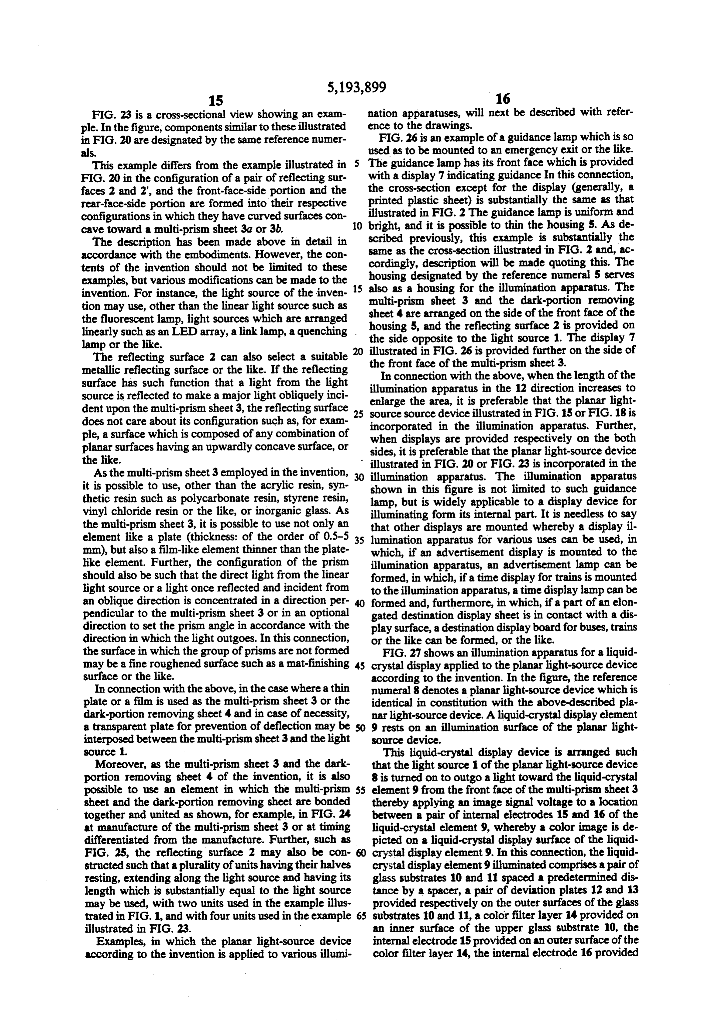
Page 25
on an inner surface of the lower glass substrate 11, and nar light-source device is brought to a waterproof con a liquid crystal 17 filled between the pair of glass sub struction or the like.
strates 10 and 11. FIG. 30 shows an illumination apparatus such as a The internal electrode 16 is constructed such that a schaukasten or the like having incorporated therein the plurality of fine picture-elements electrodes are ar 5 planar light-source device according to the invention. ranged longitudinally and laterally. Further, the color The illumination apparatus is not particularly different filter layer 14 is such that three color filters including from that illustrated in FIG. 15 except that a frame 23 red, green and blue are arranged correspondingly to the used. provided with a retainer 22 such as a film or the like is above-described picture-element electrodes to form 10 Since the invention is constructed as described above, picture elements.
The liquid-crystal display device 1 constructed as the light invention has such advantages that the light from above has such an advantage that, in the planar light the be source is effectively utilized so that there can provided the planar light-source device which is source device 8, a major portion of a light reflected by the reflecting surface 2 is obliquely incident upon the 5 bright, high in uniformity, and capable of being suffi ciently thinned. Further, the invention has such an ad multi-prism sheet 3, and the light directly or obliquely vantage that there can be provided various illumination incident upon the multi-prism sheet 3 outgoes in con apparatuses centration on the direction toward the liquid-crystal light-sourceeach having incorporated therein the planar device.
display device and, accordingly, the light from the light What is claimed is:
source 1 is effectively utilized so that there can be pro 1. An illumination apparatus used for an internal vided a liquid-crystal display device which is bright, illumination type display device comprising a box-type high in uniformity and capable of being thinned suffi housing provided ciently. It is needless to say that a digital-watch display source or a light with source a display surface, a linear light arranged linearly accommo element, a processor display element or a liquid-crystal dated in said housing, a reflecting display element for displaying guidance or advertise 25 rear face of said light source, andsurface provided at a a multi-prism sheet ment is mounted in place of the color liquid-crystal provided at an inner surface of said display surface, display element, whereby such liquid-crystal display wherein said reflecting surface has such function that device can be used as liquid-crystal display devices for a major portion of a light reflected by said reflect various uses. ing surface is obliquely incident upon said multi FIG. 28 shows an example in which the planar light 30 prism sheet, wherein said multi-prism sheet has an source device according to the invention is incorpo inner surface formed with a group of prisms so rated as an internal-illumination type display device for arranged as to extend in parallel relation to the an automatic vending machine. Such automatic vending light source and having such function that the light machine is extremely advantageous because an illumina incident directly or obliquely in reflection outgoes tion apparatus large in depth cannot be mounted in 35 in concentration toward a predetermined direction, relation to an accommodating space. and a non-directionally diffusing dark-portion re In this figure, the planar light-source device 8 accord moving sheet for eliminating a dark portion at a ing to the invention is arranged at the front face of the location immediately above the light source, ar automatic vending machine 18. It is of course, however, ranged on an outer surface of said multi-prism that the invention is not limited to this example. Since, sheet.
as the internal construction of the planar light-source 2. An illumination apparatus for use with a box-type device 8, the internal construction illustrated in FIG. 2 planar light-source device having incorporated therein can be used as it is, the description of the internal con a linear light source or a light source arranged linearly struction will be omitted. A film or the like having and provided, at its rear face, with a reflecting surface applied thereto an optional display, or the like is bonded 45 and, at its front face, with a multi-prism sheet, and a to the front face of the planar light-source device 8. In liquid-crystal display device for conducting a display in this connection, the reference numeral 19 in the figure illumination with a liquid-crystal element mounted on denotes a sample exhibiting section; 20, a charge throw the multi-prism sheet serving as a back light, character ing and operational section; and 21, a commodity tak ized in ing-out section. SO that said reflecting surface of said planar light-source FIG. 29 shows an example in which the planar light device has such function that a major portion of a source device according to the invention is incorpo light reflected by said reflecting surface is rated in an illumination apparatus which is mounted to obliquely incident upon said multi-prism sheet, a wall surface of a building. This example can widely be wherein said multi-prism sheet has its inner surface applied to wall-surface illumination apparatuses which 55 formed with a group of prisms so arranged as to are mounted, for example, to an outer wall surface or an extend in parallel relation to the light source and inner wall surface of a building, or a wa trface of an having such function that the light incident directly underground market or an undergrouz; passage, and or obliquely in reflection outgoes in concentration which is used as an illumination or an ir:tinal-illuminat toward a predetermined direction, and a non-direc ing c display. 60 tionally diffusing dark-portion removing sheet for In this example, the planar light-source device 8 ac eliminating a dark portion at a location immedi cording to the invention is mounted to the wall surface ately above the light source, arranged on an outer of the building. Since, however, the planar light-source surface of said multi-prism sheet. device 8 having its construction as shown in FIG. 2 or 3. An illumination apparatus for use with an observa FIG. 15 can be used as it is, the description of the planar 65 tion device such as a film or the like comprising a box light-source device 8 will be omitted. In this connec type housing, a linear light source or a light source tion, in the case where establishment is the outdoor, arranged linearly accommodated in said housing, a such consideration or attention is required that the pla reflecting surface provided at a rear face of said light
Page 26
source, and a multi-prism sheet provided at an inner and having such function that the light incident surface of an observation surface of said housing, char- directly or obliquely in reflection outgoes in con acterized in centration toward a predetermined direction, and a that said reflecting surface has such function that a non-directionally diffusing dark-portion removing major portion of a light reflected by said reflecting sheet for eliminating a dark portion at a location surface is obliquely incident upon said multi-prism immediately above the light source, arranged on an sheet, wherein said multi-prism sheet has its inner surface formed with a group of prisms so arranged outer surface of said multi-prism sheet. as to extend in parallel relation to the light source sk
Provenance
- Collection
- Cited prior art
- Original PDF
- patentimages.storage.googleapis.com →
- Filed
- 1991-10-31
- Pages
- 26
- Method
- pdftotext (the PDF's own text layer) + pdftoppm 300dpi page scans
- Source
- Google Patents bibliographic record
- Granted
- 1993-03-16
- Inventors
- Makoto Oe; Issei Chiba; Mitsubishi Rayon Co Ltd
- Transcribed from
- patentimages.storage.googleapis.com →