patent · US4726642
Artificial light source device
23 February 1988
Page 1 — bibliographic record
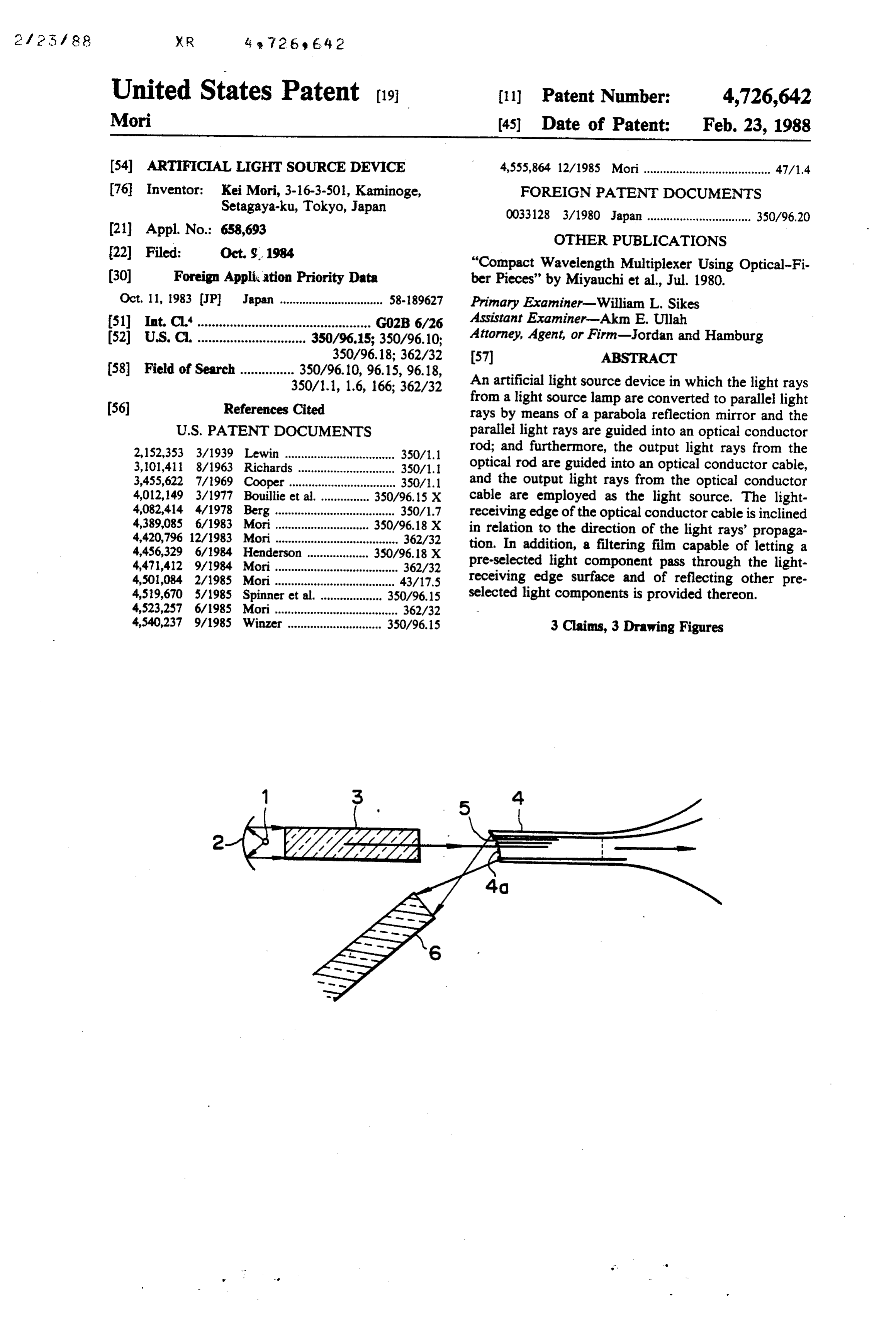
United States Patent (19. (11) Patent Number: 4,726,642 Mori (45) Date of Patent: Feb. 23, 1988 (54) ARTIFICIAL LIGHT SOURCE DEVICE 4,555,864 12/1985 Mori....................................... 47/.4 76 Inventor: Kei Mori, 3-16-3-501, Kaminoge, FOREIGN PATENT DOCUMENTS Setagaya-ku, Tokyo, Japan 0.033128 3/1980 Japan ................................ 350/96.20 21 Appl. No.: 658,693 OTHER PUBLICATIONS (22 Filed: Oct. 9, 1984 "Compact Wavelength Multiplexer Using Optical-Fi 30 Foreign Application Priority Data ber Pieces" by Miyauchi et al., Jul. 1980. Oct. 11, 1983 JP Japan ................................ 58-189627 Primary Examiner-William L. Sikes 51) Int. Cl:"................................................ GO2B 6/26 Assistant Examiner-Akin E. Ullah 52 U.S. C. .............................. 350/96.15; 350/96.10; Attorney, Agent, or Firm-Jordan and Hamburg 350/96.18; 362/32 57 ABSTRACT
350/1.1, 1.6, 166; 362/32 An artificial light source device in which the light rays
from a light source lamp are converted to parallel light rays by means of a parabola reflection mirror and the
2,152,353 3/1939 Lewin .................................. 350/1.1 rod; and furthermore, the output light rays from the 3,101,411 8/1963 Richards .. ... 350/1. optical rod are guided into an optical conductor cable, 3,455,622 7/1969 Cooper................................. 350/1.1 and the output light rays from the optical conductor 4,012,149 3/1977 Bouillie et al. 350/96.15 X cable are employed as the light source. The light 4,082,414 4/1978 Berg ..................................... 350/1.7 4,389,085 6/1983 350/96.18 X receiving edge of the optical conductor cable is inclined 4,420,796 12/1983 Mori...................................... 362/32 in relation to the direction of the light rays' propaga 4,456,329 6/1984 ... 350/96.18 X tion. In addition, a filtering film capable of letting a 4,47,412 9/1984 Mori...................................... 362/32 pre-selected light component pass through the light 4,501,084 2/1985 Mori ..................................... 43/17.5 receiving edge surface and of reflecting other pre 4,519,670 5/1985 Spinner et al. ... 350/96.15 selected light components is provided thereon. 4,523,257 6/1985 Mori...................................... 362/32 4,540,237 9/1985 Winzer ............................. 350/96.15 3 Claims, 3 Drawing Figures
Page 2
Drawing sheet — no readable text.
Page 3
ARTIFICAL LIGHT SOURCE DEVICE
of the solar rays and the source of the artificial light rays in order to employ then in an alternating way. On some
BACKGROUND OF THE INVENTION occasions it is necessary to use the solar rays and the artificial light rays from both of the light ray sources at
The present invention relates, in general, to an artific the very same time.
ial light source device, and in more detail, to one in In an artificial light source device as described above, which the light rays from a light source lamp are con the light rays from an artificial light source lamp are verted to parallel light rays by means of a parabola converted to parallel light rays. The parallel light rays reflection mirror and the parallel light rays are guided O are guided into an optical conductor rod and are further into an optical conductor rod. Furthermore the light guided through it into another optical conductor cable. rays coming from the optical rod are then guided into When the light rays from the artificial light source lamp the optical conductor cable and the light rays coming are guided through the optical conductor rod into the from the optical conductor cable are then employed as optical conductor cable in such a manner, the heat rays a light source. In such a device, the light-receiving edge and the ultraviolet rays are among the light rays from of the optical conductor cable is inclined in relation to 15 the artificial light source, and the light rays or visible the direction of the light rays' propagation. In addition rays can be effectively guided into the optical conduc to that, a filtering film capable of letting a pre-selected tor cable.
part of the light pass through the light-receiving edge surface and of reflecting other pre-selected portions of SUMMARY OF THE INVENTION the light thereon, is provided in this proposed device. In 20 It is the primary object of the present invention to such a manner, a part of the light is separated from the provide an artificial light source device which is an rest by means of a filtering film.
In general, it is possible to illuminate any place improvement over previous devices. through the use of an electric lamp. However, in the vide an artificialobject
It is another of the present invention to pro light source in which a pre-selected case of illuminating in an explosive atmosphere or in 25 light component, for instance ultraviolet rays, is pre water, there necessarily exists a danger of explosion or vented from being guided into an optical conductor electric leakage. For this reason, the electric instrument cable.
to be used in such places has to be of an explosion-proof It is another object of the present invention to pro type or a water-proof type. However, in the past, such an explosion-proof or water-proof instrument was 30 vide an artificial light source in which more high-qual heavy and expensive when completed, and it was also ity light components, for instance visible rays, can be impossible to manufacture such completely explosion guided into an optical conductor cable. proof or water-proof instruments as made possible by It is another object of the present invention to pro this new device. vide an artificial light source device comprised of a light Furthermore, the present applicant has previously 35 source lamp, a reflection mirror for reflecting light rays proposed a light compound reaction device for nurtur from the light source lamp in the form of parallel light ing chlorella or the like and an intensive cultivation rays, an optical conductor rod having a light-receiving device for cultivating plants in an atmosphere contain edge surface placed opposed the reflection mirror, the ing carbon dioxide (carbonic acid gas). In such devices, parallel light rays being guided into an optical conduc the light rays are necessary for creating a light com tor rod and an optical conductor cable, a light-receiving pound reaction. In order to emit the necessary light rays edge surface of which is placed at the light-emitting for achieving its purpose, it needs to have a large num edge surface of the optical conductor rod so as to be ber of small spotlight sources without emitting any heat opposite the light-emitting edge surface thereof and and ultraviolet rays. In order to obtain the light source which employs the light rays from the optical conduc as mentioned above, the present applicant has previ 45 tor cable as a light source, the light-receiving edge ously proposed various methods and apparatuses in surface of the optical conductor cable being inclined in which solar rays are focused by a lens or the like and relation to the direction of the light rays' propagation, guided into an optical conductor cable consisting of a and a filter for letting only pre-selected light component large number of optical fibers, and the solar rays are pass through the inclined surface and for reflecting further guided through the optical conductor cable into SO other pre-selected light components thereon is provided the light compound reaction device of the chlorella in the artificial light source device. nurturing device or the intensive plant cultivation de BRIEF DESCRIPTION OF THE DRAWINGS vice, and the light rays emitted from the optical fiber are employed as a spotlight source. In this regard, refer FIG. 1 is a cross-sectional view showing a prior art ence is made to U.S. Pat. No. 4,389,085 issued June 21, 55 artificial light source device. 1983; No. 4,420,796 issued Dec. 13, 1983; No. 4,471,412 FIGS, 2 and 3 are cross-sectional views for explain issued Sept. 11, 1984; No. 4,523,257 issued June 11, ing the construction of the first and second embodi 1985; No. 4,555,864 issued Dec. 3, 1985; and U.S. patent ments according to the present invention. application SerNo. 520,337 filed Aug 4, 1983 U.S. Pat.
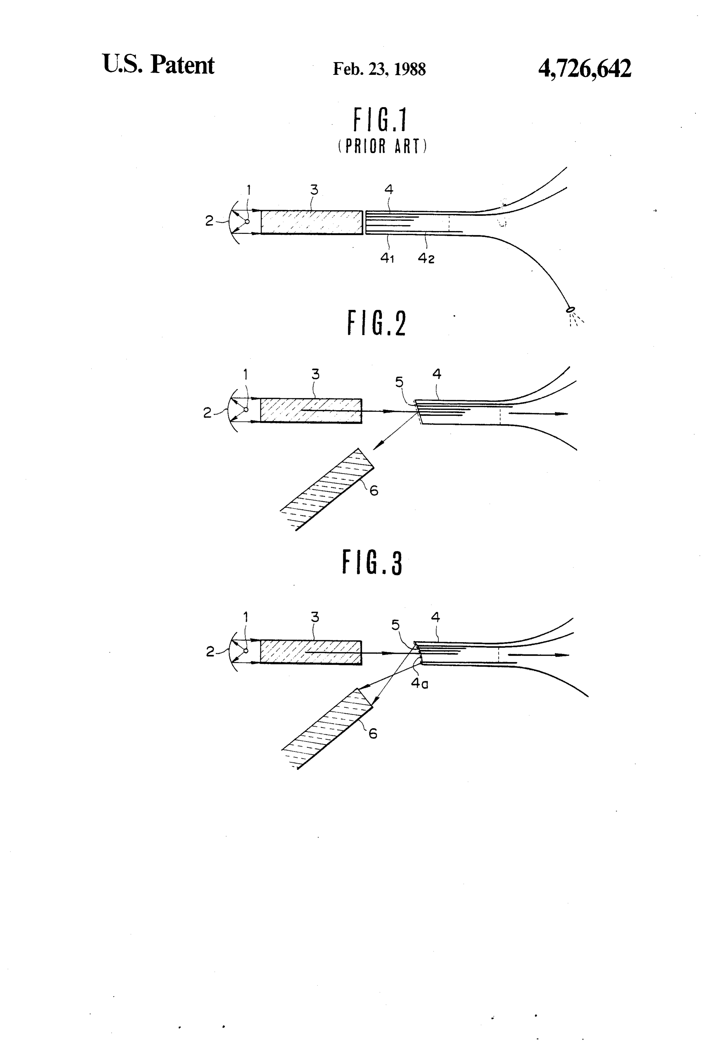
No. 4,501,084. DESCRIPTION OF THE PREFERRED However, if the light compound reaction device is EMBODIMENTS effective even in the night time, only artificial light rays FIG. 1 is a cross-sectional view showing an embodi are employed instead of solar rays as the main light ment of the artificial light source device previously source. In such a case, the light rays from the artificial proposed by the present applicant. In FIG. 1, 1 is an light source lamp are guided into the optical conductor 65 artificial light source lamp, 2 is a reflection mirror i.e. a cable and further guided through the optical conductor parabola reflection mirror for converting light rays cable into the light compound reaction device. In such from the artificial light source lamp 1 to parallel light a device it is necessary to switch alternately the source rays and for reflecting thereon. 3 is an optical conductor
Page 4
rod for receiving the parallel light rays from the reflec guided into another optical conductor cable 6 for em tion mirror 2, and 4 is an optical conductor cable con ploying then in a desired way. sisting of a large number of optical fibers 41, 42, etc. Moreover, an absorptive filter can be employed in As shown in FIG. 1, the light rays from the artificial stead of a reflective filter. However, if the absorptive light source lamp 1 are converted to parallel light rays. filter is employed, the light components absorbed are The parallel light rays are initially guided into the opti converted to heat and the property of matter is thereby cal conductor rod 3, and then further guided through thermally changed. Therefore, the absorptive filter may the optical conductor rod 3 into the optical conductor not be preferable for that reason.
cable 4. Furthermore, when the light rays from the An embodiment for separating the ultraviolet rays artificial light source lamp 1 are guided through the O and the infrared rays from the artificial light source's optical conductor rod into the optical conductor cable light rays is described heretofore. However, the present in such a manner, the heat rays and the ultraviolet rays invention is not limited to the afore-mentioned embodi are among the light rays from the artificial light source, ment. For instance, in the case of nurturing, cultivating, and the light rays can be effectively guided into the and testing non-bacterial animals or plants, it is neces optical conductor cable. 15 sary to prohibit persons from entering the testing room. However, in an artificial light source according to the In such a case, according to the present invention, the present invention, pre-selected light components, for light-emitting edge side of the optical conductor cable is instance ultraviolet rays, are prevented from being guided into the non-bacterial room and the light source guided into the optical conductor cable effectively and lamp can be put outside of it. Therefore, when the light as a result more high-quality light components, for in 20 source lamp is broken, persons need not enter the non stance visible rays, can be guided into the optical con bacterial room, making it very convenient. ductor cable. Furthermore, in such a case, the necessary light con FIG. 2 is a cross-sectional view for explaining an ponents and the unnecessary or harmful light compo embodiment of the present invention. In FIG. 2, the nents will differ depending on the kinds of animals or same reference numeral as FIG. 1 is attached to the part 25 plants to be nurtured or cultivated there. On such an performing the same action as that of FIG. 1. In the occasion, a suitable filter has to be selected in relation to present invention, the light-receiving edge of the optical the kinds of animals or plants. Furthermore, the light conductor cable 4 is slightly inclined in relation to the components from the light source lamp may be em direction of the propagation of the light rays and a ployed also in accordance with the kinds of animals or filtering film, for instance a gold evaporation layer 5 30 plants.
capable of letting the visible rays pass through and of As is apparent from the foregoing description, ac reflecting the ultraviolet rays thereon, is provided on cording to the present invention, a specially designed the inclined surface. As a consequence, among the par light component, for instance, an ultraviolet ray compo allel light rays from the optical conductor rod 3, the nent can be effectively separated from among the light ultraviolet rays and the infrared rays are reflected by 35 rays coming from an artificial light source lamp, and the the filtering film 5 and taken out therefrom, and only more high-quality light rays for instance visible rays, the visible rays are guided into the optical conductor can be guided into the optical conductor cable. cable 4. y - What is claimed is:
As mentioned heretofore, according to the present 1. An artificial light source device comprising a light invention, the light-receiving edge of the optical con source lamp, a reflection mirror for reflecting light rays ductor cable 4 is established so as to be slightly inclined from said light source lamp in the form of parallel light in relation to the direction of the light rays' propaga rays, an optical conductor rod having a first light tion. If the light-receiving edge of the optical conductor receiving end surface and a first light-emitting end sur cable 4 is not inclined at all, the ultraviolet rays re face, said first light-receiving end surface being dis flected by the filtering film 5 are at this time inversely 45 posed opposite said reflection mirror, said optical con transmitted through the optical conductor rod 3 to the ductor rod having a longitudinal axis, said parallel light light source lamp side and are reflected thereon and rays being guided into said optical conductor rod paral propagated to the optical conductor cable side again. lel to said longitudinal axis, an optical conductor cable After the repetition of such a cycle, almost all of the having a concave light-receiving end surface disposed ultraviolet rays and infrared rays are guided into the 50 opposite to and spaced from said first light-emitting end optical conductor cable. If the light-receiving edge surface of said optical conductor rod such that there is surface of the optical conductor cable 4 is inclined in a first space between said concave light-receiving end relation to the direction of the light rays' propagation, surface and said first light-emitting end surface and the as shown in the present invention, the light rays re light rays pass from said first light-emitting end surface flected on the inclined surface do not propagate to the 55 through said first space to said concave light-receiving light source side. end surface, filter means on said concave surface opera FIG. 3 is a cross-sectional view for explaining the ble to pass only a pre-selected light component through construction of another embodiment according to the the filter means to said optical conductor cable, said present invention. In that embodiment, the light-receiv concave surface and said filter means reflecting and ing edge 4a of the optical conductor cable 4 is shaped in focusing other pre-selected hight components in a direc a concave fashion. By using such a shape, the parallel tion which extends at an acute angle relative to the light rays from the optical conductor rod 3 can not only longitudinal axis of said optical conductor rod, and an be guided more effectively into the optical conductor 4, optical conductor means having a longitudinal axis but also the reflected light rays are focused, so that they disposed at an acute angle relative to the longitudinal can be effectively guided into the optical conductor 6. 65 axis of said optical conductor rod, said optical conduc The ultraviolet rays taken out in such a manner as tor rod and said optical conductor means being spaced mentioned before may be allowed to dissipate. How from one another, said optical conductor means having ever, on some occasions, the ultraviolet rays may be a second light-receiving end surface, said second light
Page 5
receiving surface being disposed opposite to and spaced wherein said filter means comprises a gold film which is from said concave surface having said filter means thereon such that there is a second space between said evaporated onto said concave surface. second light-receiving end surface and said concave 3. An artificial light source according to claim 1, surface and said reflected and focused other pre- 5 wherein said filter means is disposed on the outside of selected light components pass through said second - - - - space into said optical conductor means. said concave surface within said first and second spaces. 2. An artificial light source according to claim 1, x : x :
Provenance
- Collection
- Cited prior art
- Original PDF
- patentimages.storage.googleapis.com →
- Filed
- 1984-10-09
- Pages
- 5
- Method
- pdftotext (the PDF's own text layer) + pdftoppm 300dpi page scans
- Source
- Google Patents bibliographic record
- Granted
- 1988-02-23
- Inventors
- Kei Mori
- Transcribed from
- patentimages.storage.googleapis.com →