patent · US1380835
Artificial limb
7 June 1921
Page 1
Drawing sheet — no readable text.
Page 2
Drawing sheet — no readable text.
Page 3
UNITED STATES PATENT OFFICE.
ALBERTO PECORELLA AND WINCENT PATRICOLO, OF BUFFALO, AND FREDERICK H.
APEL, OF ATHOL SPRINGS, NEW YORK.
ARTIFICIAT LIMIB.
1,880,885. Specification of Letters Patent. Patented June 3, 1921. Application filed October 23, 1919. Serial No. 332,698.
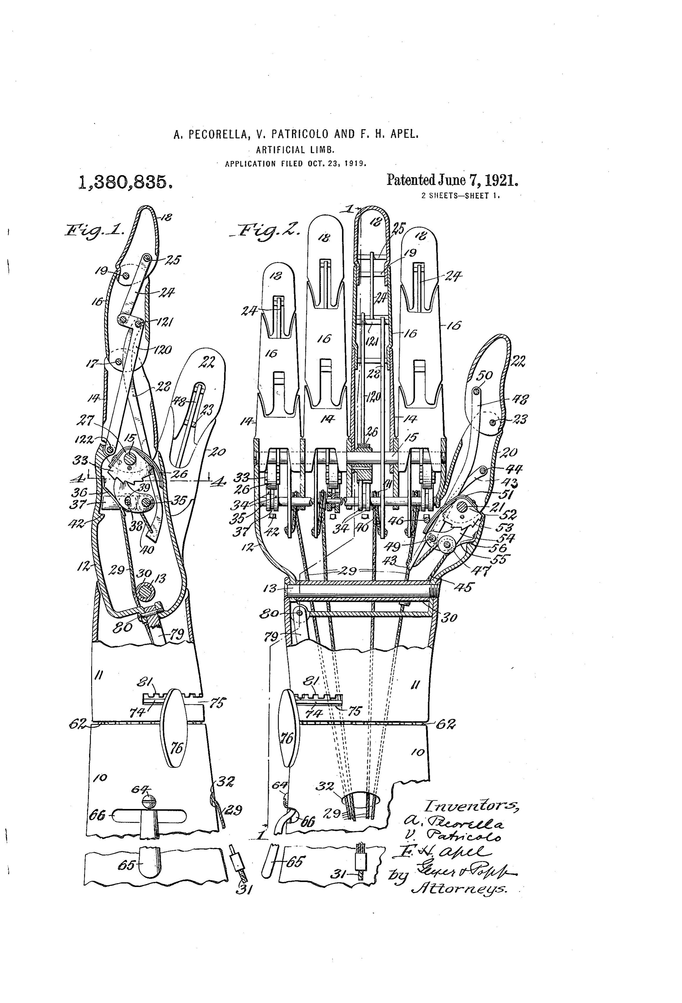
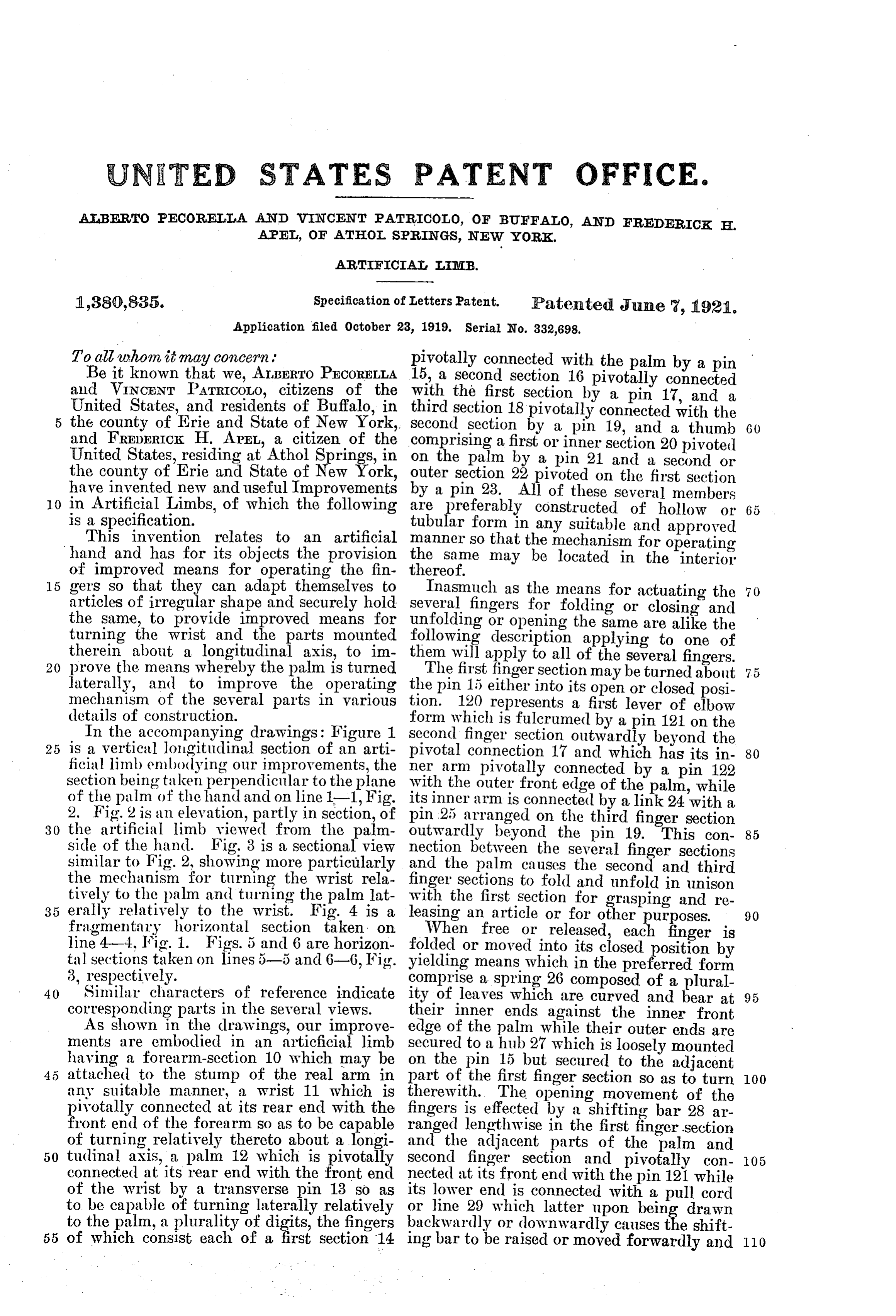
To all whom it may concern; pivotally connected with the palm by a pin Be it known that we, ALBERTO PECORELLA 15, a second section 16 pivotally connected and WINCENT PATRICOLO, citizens of the With the first section by a pin 17, and a United States, and residents of Buffalo, in third section 18 pivotally connected with the the county of Erie and State of New York, Second section by a pin 19, and a thumb 60 and FREDERICK H. APEL, a citizen of the
United States, residing at Athol Springs, in comprising on the palm a first or inner section 20 pivoted by a pin 21 and a second or the county of Erie and State of New York, Outer section 22 have invented new and useful Improvements by a pin 28. Allpivoted of on the first section these several members 0. in Artificial Limbs, of which the following are Preferably constructed of hollow or 65 is a specification.
This invention relates to an artificial tubular form in any suitable and approved hand and has for its objects the provision the same that manner so may the mechanism for operating be located in the interior of improved means for operating the fin thereof.
15 gers so that they can adapt themselves to Inasmuch as the means fororactuating the articles of irregular shape and Securely hold Several fingers for folding closing and the same, to provide improved means for unfolding or opening the same are alike the turning the wrist and the parts mounted following description applying to one of therein about a longitudinal axis, to im then will apply to all of the several fingers. 20 prove the means whereby the palm is turned laterally, and to improve the operating theThe pin first finger section may be turned about 75 15 either into its open or closed posi mechanism of the several parts in various tion. 120 represents a first lever of elbow details of construction.
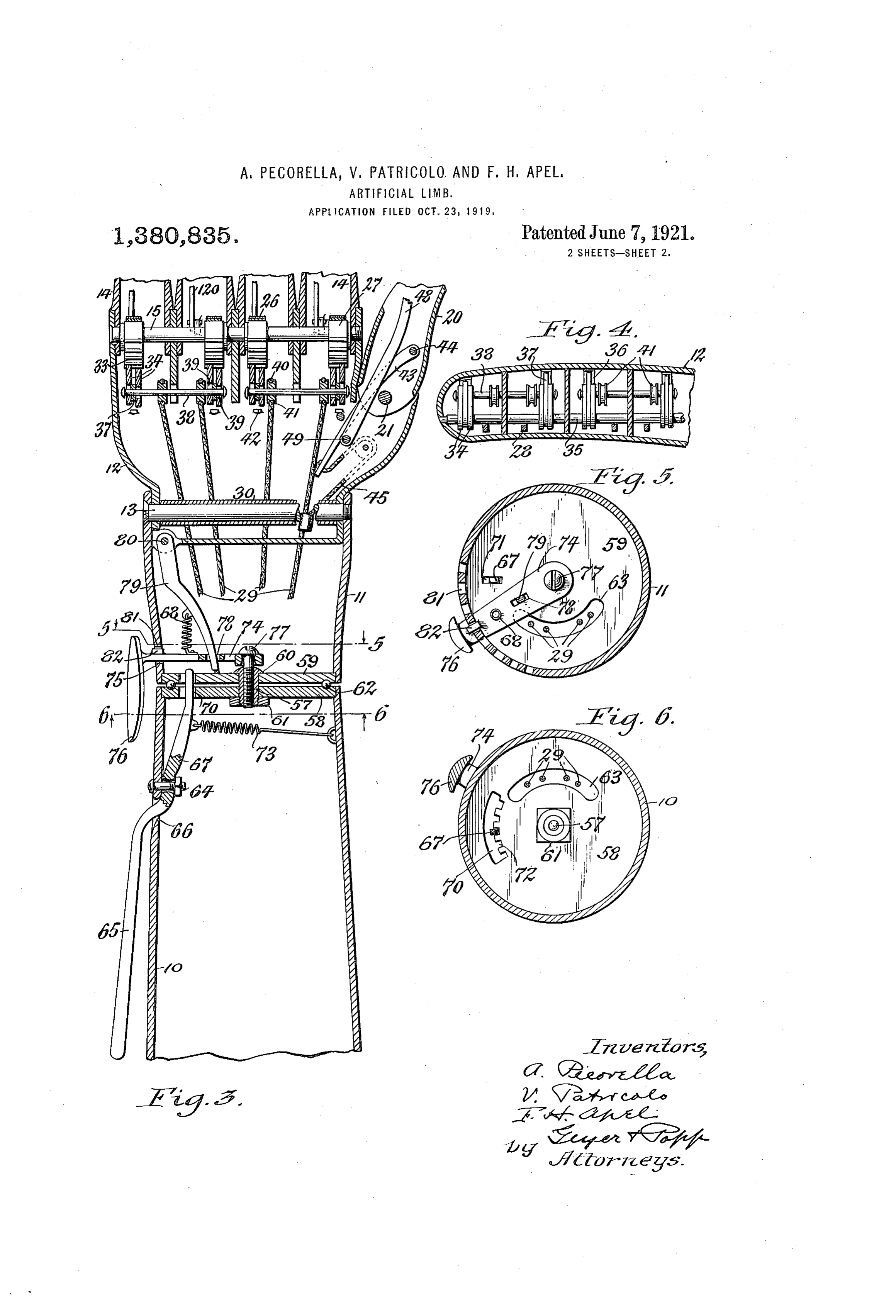
In the accompanying drawings: Figure 1. form which is fulcrumed by a pin 121 on the Second finger Section outwardly beyond the 25 is a vertical longitudinal section of an arti pivotal connection 17 and which has its in 80 ficial limb embodying our improvements, the ner arm pivotally connected by a pin 122 section being taken perpendicular to the plane With the outer front edge of the palm, while of the palm of the hand and on line 1-1, Fig. inner arm is connected by a link 24 with a 2. Fig. 2 is an elevation, partly in section, of its pin 25 arranged on the third finger section 30 the artificial limb viewed from the palm outyardly beyond the pin 19. This con 85 side of the hand. Fig. 3 is a sectional view nection between the several finger sections similar to Fig. 2, showing more particularly and the palm causes the second and third the mechanism for turning the wrist rela finger sections to fold and unfold in unison tively to the palm and turning the palm lat with the first section for grasping and re 35 erally relatively to the wrist. Fig. 4 is a leasing an article or for other purposes. 90 fragmentary horizontal section taken on When free or released, each finger is line 4-4, IFig. 1. Figs. 5 and 6 are horizon folded tal sections taken on lines 5-5 and 6—6, Fig. yieldingormeans moved into its closed position by which in the preferred form 3, respectively. complise a Spring 26 composed of a plural 40 Similar characters of reference indicate ity of leaves which are curved and bear at 95 corresponding parts in the several views. their inner ends against the inner front As shown in the drawings, our improve edge of the palm while their outer ends are ments are embodied in an articficial limb Secured to a hub 27 which is loosely mounted having a forearm-section 10 which may be on the pin 15 but Secured to the adjacent attached to the stump of the real arm in part of the first finger section so as to turn 00 any suitable manner, a wrist 11 which is therewith. The opening movement of the pivotally connected at its rear end with the fingers is effected by a shifting bar 28 ar front end of the forearm so as to be capable ranged lengthwise in the first finger section of turning relatively thereto about a longi and the adjacent parts of the palm and 50 tudinal axis, a palm 12 which is pivotally Second finger section and pivotally con 05 connected at its rear end with the front end nected at its front end with the pin 121 while of the wrist by a transverse pin 13 so as its lower end is connected with a pull cord to be capable of turning laterally relatively or line 29 which latter upon being drawn to the palm, a plurality of digits, the fingers backwardly or downwardly causes the shift 55 of which consist each of a first section 14 ing bar to be raised or moved forwardly and 110
Page 4
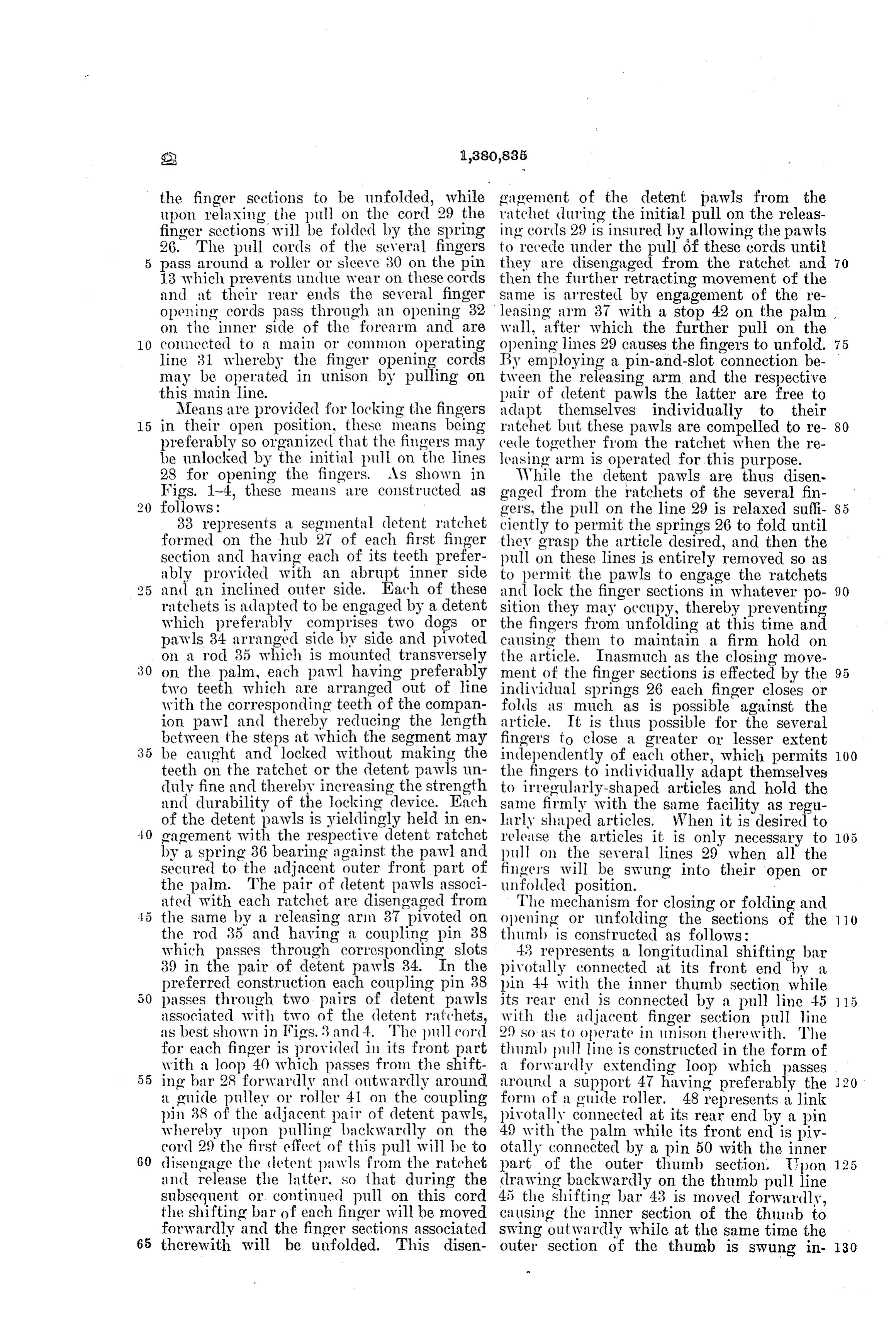
the finger sections to be unfolded, while gagement of the detent pawls from the upon relaxing the pull on the cord 29 the ratchet during the initial pull on the releas finger sections will be folded by the spring ing cords 29 is insured by allowing the pawls 26. The pull cords of the several fingers to recede under the pull Óf these cords until 70 pass around a roller or sieeve 30 on the pin they are disengaged from the ratchet and i3 which prevents undue wear on these cords then the further retracting movement of the and at their rear ends the several finger same is arrested by engagement of the re opening cords pass through an opening 82 leasing arm 37 with a stop 42 on the palm on the inner side of the forearm and are wall, after which the further pull on the 10 connected to a main or common operating opening lines 29 causes the fingers to unfold. 75 line 31 whereby the finger opening cords By employing a pin-and-slot connection be may be operated in unison by pulling On tween the releasing arm and the respective this main line. pair of detent pawls the latter are free to Means are provided for locking the fingers adapt themselves individually to their 15 in their open position, these means being ratchet but these pawls are compelled to re 80 preferably so organized that the fingers may cede together from the ratchet when the re be unlocked by the initial pull on the lines easing arm is operated for this purpose. 28 for opening the fingers. As shown in While the detent pawls are thus disen Figs. 1-4, these means are constructed as gaged from the ratchets of the several fim follows: gers, the pull on the line 29 is relaxed suffi 85 33 represents a segmental detent ratchet ciently to permit the springs 26 to fold until formed on the hub 27 of each first finger they grasp the article desired, and then the section and having each of its teeth prefer pull on these lines is entirely removed so as ably provided with an abrupt inner side to permit the pawls to engage the ratchets and an inclined outer side. Each of these and lock the finger sections in whatever po 90 ratchets is adapted to be engaged by a detent sition they may occupy, thereby preventing which preferably comprises two dogs or the fingers from unfolding at this time and pawls 34 arranged side by side and pivoted causing them to maintain a firm hold on on a rod 35 which is mounted transversely the article. Inasmuch as the closing move 30 on the palm, each pawl having preferably ment of the finger sections is effected by the two teeth which are arranged out of line individual springs 26 each finger closes or with the corresponding teeth of the compan folds as much as is possible against the ion pawl and thereby reducing the length article. It is thus possible for the several between the steps at which the segment may fingers to close a greater or lesser extent 35 be caught and locked without making the independently of each other, which permits 100 teeth on the ratchet or the detent pawls um the fingers to individually adapt themselves duly fine and thereby increasing the strength to irregularly-shaped articles and hold the and durability of the locking device. Each same firmly with the same facility as regu of the detent pawls is yieldingly held in en larly shaped articles. When it is desired to 40 gagement with the respective detent ratchet release the articles it is only necessary to 05 by a spring 36 bearing against the pawl and pull on the several lines 29 when all the secured to the adjacent outer front part of finger's will be swung into their open or the palm. The pair of detent pawls associ unfolded position.
ated with each ratchet are disengaged from The mechanism for closing or folding and the same by a releasing arm 37 pivoted on opening or unfolding the sections of the 10 the rod 35 and having a coupling pin 38 thumb is constructed as follows: which passes through corresponding slots 43 represents a longitudinal shifting bar 39 in the pair of detent pawls 34. In the pivotally connected at its front end by a preferred construction each coupling pin 38 pin 44 with the inner thumb section while passes through two pairs of detent pawls its rear end is connected by a pull line 45 15 associated with two of the detent ratchets, with the adjacent finger section pull line as best shown in Figs, 3 and 4. The pull cord 29 SO as to operate in unison there with. The for each finger is provided in its front part thumb pull line is constructed in the form of with a loop 40 which passes from the shift a forwardly extending loop which passes 55 ing bar 28 forwardly and outwardly around around a support 47 having preferably the 120 a guide pulley or roller 41 on the coupling form of a guide roller. 48 represents a link pin 38 of the adjacent pair of detent pawls, pivotally connected at its rear end by a pin whereby upon pulling backwardly on the 49 with the palm while its front endis piv cord 29 the first effect of this pull will be to otally connected by a pin 50 with the inner 60 disengage the detent pawls from the ratchet part of the outer thumb section. Upon 125 and release the latter, so that during the drawing backwardly on the thumb pull line subsequent or continued pull on this cord 45 the shifting bar 43 is moved forwardly, the shifting bar of each finger will be moved causing the inner section of the thumb to forwardly and the finger sections associated Swing outwardly while at the same time the 65 therewith will be unfolded. This disen outer section of the thumb is swung in- 130
Page 5
wardly by the link 48. When the inner The plates 58, 59 are provided with corre thumb section 20 is swung inwardly the sponding openings 63, preferably of Seg outer section 22 is swung outwardly rela mental form through which the pull lines tively to the fingers. In this way the nat 29 pass and which permit the forearm and 5 ural movement of the hand is simulated in wrist to turn relatively to each other with 70 that the tip of the thumb swings slightly out interference from said lines. away from the palm of the hand while the Means are provided for turning the wrist fingers are folding and thus cause the fin relatively to the forearm and locking the gers and thumb to close around or adapt same in various positions relatively to each 10 themselves to the object to be grasped in a other without requiring the use of a natural 75 manner closely resembling the action of a hand for this purpose. The preferred form human hand. . of these means as shown in the drawings The folding action of the thumb sections comprises a longitudinal adjusting lever 65 is effected when the latter are free by means pivoted by a swivel joint on a bolt 64 to 5 of a spring 51 preferably of leaf form, the forearm so as, to swing croSSwise rela 80 which is secured at its outer end to a hub tively thereto and having a rear arm 65 52 which is mounted on the rear end of the projecting through an opening 66 in the inner thumb section, so as to turn therewith forearm to the exterior thereof while its while its inner end bears against an abut front arm 67 projects through a circum 85 20 {?? pin 46 on the adjacent part of the ferential slot 70 in the forearm plate, 58 palm. and into a radial slot 71 in the wrist plate For the purpose of locking the thumb sec 59. The inner edge of the slot 70 is pro tions against unfolding while an article is vided with a plurality of notches 72 which grasped by the hand, a locking device is are arranged in a circumferential row and 25 provided which preferably consists of a seg the front arm 67 of the wrist adjusting le 90 mental ratchet 53 formed on the hub 52, a ver is held in engagement with one or an detent pawl 54 pivoted on the pin 49 and other of these notches by a spring 73 which carrying the roller 47, a spring 55 mounted connects the front arm 67 with the adjacent on the palm and bearing against the pawl part of the forearm. When it is desired to 30 54 for moving the same into engagement turn the wrist relatively to the forearm, the with the ratchet 53, and a stop 56 arranged rear arm 65 of the wrist shifting lever is on the palm and adapted to be engaged by first moved inwardly, and then pressed side the pawl 54 for limiting its movement away wise, thereby first unlocking this lever from from the ratchet. the notched edge of the slot 70 and then 35 Upon pulling on the lines 29 and 45 for turning the wrist relatively to the forearm. 00 adapting the hand to an article to be After the Wrist has been turned the required grasped, the first effect of the line 45 is to extent the pressure against the rear arm 65 withdraw the pawl 54 from the ratchet 53 is released, whereby the spring 73 draws and thus permit, the inner section to be its front arm 67 into engagement with the 40 swung inwardly by the spring 55 and the adjacent notch 72 and locks the wrist against 105 outer thumb section to be swung outwardly turning out of this position. by the link 48 upon partly relaxing the pull Means are provided for rocking the palm on these lines. When the thumb and finger laterally relatively to the wrist and holding sections have reached the desired position, the same in various positions relatively to O 45 the pull on the lines 29 and 45 is fully re each other, which means are constructed as laxed, thereby permitting the detent pawls follows: wM of the fingers and thumb to engage their re 74 represents an adjusting lever project spective ratchets and hold the fingers and ing laterally through a circumferential slot thumb sections in their folded position. 75 in the rear part of the Wrist and pro 50 The pivotal connection between the wrist vided outside of the latter with a head or 15 and forearm for turning these members handle 76 while its inner end is pivoted by about a longitudinal axis relatively to each a swivel joint to the front end of a screw 77 other preferably comprises a longitudinal which is secured axially to the bolt 57 which pivot bolt 57 passing through correspond couples the plates 58, 59. This adjusting 55 ing openings formed centrally in two plates lever is provided with a slot or opening 78 20 58, 59 which are mounted on the opposing which receives the lower or rear end of a ends of the forearm and wrist, the head 60 shifting arm 79, the latter being pivoted at and nut 61 of said bolt bearing against the its upper or front end on the wrist by a opposite sides of said plates, as shown in pin or screw 80 so as to permit the shifting 60 Fig. 3. Near the margins of these plates arm to swing radially relatively to the axis 25 their opposing surfaces are provided with of the wrist but compelling the same to turn annular ball races which receive a row of bodily with the wrist about the pivotal con balls 62 whereby the rotary movement of nection between the palm and the wrist. the wrist is relieved of undue friction, noise The upper side of the slot 78 is constructed 65 and wear. to form a segmental row of notches 81 and 130
Page 6
the upper side of the adjusting arm is pro finger pivotally connected with said palm 65 vided with a tooth 82 which is yieldingly and having a plurality of pivotally connect held in engagement with one or another of ed Sections, a shifting bar connected with the these notches by a spring 68 which connects finger Sections, a pull line connected with the adjusting lever 74 with the shifting said bar and having a forwardly extending arm 79. loop, a ratchet connected with the rearmost 70 When it is desired to tilt the palm more finger Section, a detent pawl engaging said or less the adjusting lever 74 is first pressed ratchet, and a guide roller which is mov backwardly or downwardly to disengage the able bodily with said pawl and around which 10 same from the respective notch 81 and then Said loop passes.
turned circumferentially relatively to the 5. An artificial limb comprising a palm, a 75 wrist in one direction or the other, which finger pivotally connected with said palm movement is transmitted to the palm by the and having a plurality of pivotally connect shifting arm 79. When the palm has ed sections, a shifting bar connected with the 15 reached the desired position the adjusting finger sections, a pull line connected with lever 74 is released and permitted to inter said bar and having a forwardly extending 80 lock with the adjacent notch 81 by the spring loop, a ratchet connected with the rearmost 68, thereby holding the palm in its adjusted finger section, a detent pawl engaging said position. By pivoting the shifting arm 79 ratchet, a guide roller which is movable bod 20 on the palm, eko same is free to follow the ily with said pawl and around which said adjusting lever 74 as the same Swings around loop passes, and a stop for limiting the move 85 ment of Said detent pawl away from said the axis of the pivotal connection between the ratchet.
wrist and forearm without producing any cramping action of the parts. 6. An artificial limb comprising a palm, a 25 The operation of the adjusting levers finger pivotally connected with said palm 65-67 and 74 may be effected by engaging and having a plurality of pivotally connect 90 the same with any object such as the body ed Sections, a shiftino bar connected with of a person, or the surface of a table, chair the finger sections, a pull line connected with or the like, thus enabling this adjustment to said bar and having a forwardly extending 30 be effected without the use of any hand. loop, a ratchet connected with the rearmost A change of position of the fingers and finger section, a detent pawl engaging said 95 thumb is thus possible in order to simulate ratchet and provided with a slot, a releasing a natural hand without attracting the at arm provided with a pin engaging with said tention of other persons, and thereby avoid slot, a roller arranged on said pin and receiv 35 ing the annoyance and embarrassment usu ing said loop, and a stop which limits the ally attending the adjustment of artificial movement of said arm and pawl away from 00 hands. said ratchet.
We claim as our invention: 7. An artificial limb comprising a palm, a 1. An artificial limb comprising a palm, a finger pivotally connected with said palm 40 finger pivoted on said palm, and means Op and having a plurality of pivotally con erating constantly to turn said finger into nected sections, a shifting bar connected 05 a closed position relatively to said palm com with the finger sections, a pull line connected prising a hub mounted on the finger, and a with said bar and having a forwardly ex leaf spring secured at one end to said hub tending loop, a ratchet connected with the and engaging its opposite end with said rearmost finger section, a pair of detent palm. pawls having differently arranged teeth 0 2. An artificial limb comprising a palm, a engaging the ratchet and provided with finger pivoted on said palm and having a slots, a releasing arm provided with a cou plurality of pivotally connected Sections, pling pin arranged in Said slots, a guide and means for unfolding said finger Sections roller arranged on Said pin and receiving comprising a shifting bar connected at its Said loop, and a stop for limiting the move 15 front end with said finger sections, and a ment of Said a'm away from said ratchet. pull line connected with the rear end of Said 8. An artificial limb comprising a palm, bar. W a thumb having an inner section pivoted to 3. An artificial limb comprising a palm, a said palm and an outer section pivoted on finger pivoted on said palm and having a said inner section, a shifting bar connected 20 plurality of pivotally connected Sections, and at its front end with said inner section, and means for unfolding said finger sections a link connecting said palm with said outer comprising a shifting bar connected at its section.
60 front end with said finger sections, a pull line 9. An artificial limb comprising a palm, connected with the rear end of Said bar and a thumb having an inner section pivoted to having a forwardly extending loop, and a said palm and an outer section pivoted on support around which said loop passes. said inner section, a shifting bar connected 4. An artificial limb comprising a palm, a at its front end with said inner section, a
Page 7
link connecting said palm with said outer laterally relatively thereto, and means for 50 section, and a pull line connected with said adjusting said palm comprising an adjust shifting bar. ing lever pivoted on the wrist and opera 10. An artificial limb comprising a palm, tively connected with said palm, said wrist a thumb having an inner section pivoted to being provided with a row of notches with said palm and an outer section pivoted on which said lever is adapted to engage. 55 said inner section, a shifting bar connected 15. An artificial limb comprising a wrist at its front end with said inner section, a provided in its side with a slot having one of link connecting said palm with said outer its circumferential edges constructed to form O section, a pull line connected with said shift a row of notches, a palm pivoted on said ing bar and having a forwardly extending wrist to swing laterally relatively thereto, 60 loop, and a support around which said loop an adjusting lever pivoted by a swivel con passes. nection to said wrist and projecting through 11. An artificial limb comprising a palm, said slot, a shifting arm pivotally connected 5 a thumb having an inner section pivoted to at one end with said lever and pivoted at its said palm and an outer section pivoted on opposite end on said palm so as to be capable 65 said inner section, a shifting bar connected of swinging radially relatively to said lever at its front end with said inner section, a but compelled to turn with said palm about link connecting said palm with said outer the axis of the latter, and a spring connect 20 section, a pull line connected with said ing said arm and lever and operating to hold shifting bar and having a forwardly extend the latter yieldingly in engagement with one 70 ing loop, a roller around which said loop of said notches.
passes, a spring operating to fold said inner 16. An artificial limb comprising a fore section, a ratchet connected with the inner arm, a wrist pivoted on said forearm to turn 25 section, a detent pawl engaging said ratchet about the longitudinal axis of the same, and and carrying said roller, a spring for mov means for adjusting said wrist relatively to ing said pawl toward said ratchet, and a said forearm comprising a lever pivoted on stop for limiting the movement of said pawl said forearm and having one end projecting away from said ratchet. on the exterior of the same while its other 30 12. An artificial limb comprising a wrist, end is operatively connected with said wrist. a palm pivoted on said wrist so as to swing 17. An artificial limb comprising a fore 80 laterally relatively thereto, and means for arm, a wrist pivoted on said forearm to turn adjusting said palm comprising an adjust about the longitudinal axis of the same, and ing lever pivoted on the wrist, and 35 arm mounted on the palm and engaging a shifting means for adjusting said wrist relatively to said forearm comprising a lever pivoted by with said lever. . a swivel joint on said forearm and having a 85 13. An artificial limb comprising a wrist, rear arm extending to the exterior of the a palm pivoted on said wrist so as to swing forearm, a plate arranged on the forearm laterally relatively thereto, and means for 40 adjusting said palm comprising an adjust and provided with a row of notches, a plate arranged on the wrist and provided with a ing lever pivoted on the wrist and provided radial slot which is engaged by the front 90 with an opening, and a shifting arm engag arm of said lever, and a spring connecting ing one end with said opening and pivoted said lever and forearm and operating to hold at its opposite end to said palm so as to be said front arm yieldingly in engagement 45 free to swing radially relatively to said lever with said notches. but compelled to turn with the palm about the axis of the latter. ALBERTO PECORELLA. 14. An artificial limb comprising a wrist, WINCENT PATRICOLO. a palm pivoted on said wrist so as to swing EREDERICK H. APEL.
Provenance
- Collection
- Cited prior art
- Original PDF
- patentimages.storage.googleapis.com →
- Filed
- 1919-10-23
- Pages
- 7
- Method
- pdftotext (the PDF's own text layer) + pdftoppm 300dpi page scans
- Source
- Google Patents bibliographic record
- Granted
- 1921-06-07
- Inventors
- Pecorella Alberto; Patricolo Vincent; Frederick H Apel
- Transcribed from
- patentimages.storage.googleapis.com →