patent · US1975805
Art and apparatus for sterilizing
9 October 1934
Page 1
Drawing sheet — no readable text.
Page 2
Drawing sheet — no readable text.
Page 3
Drawing sheet — no readable text.
Page 4
Drawing sheet — no readable text.
Page 5
Drawing sheet — no readable text.
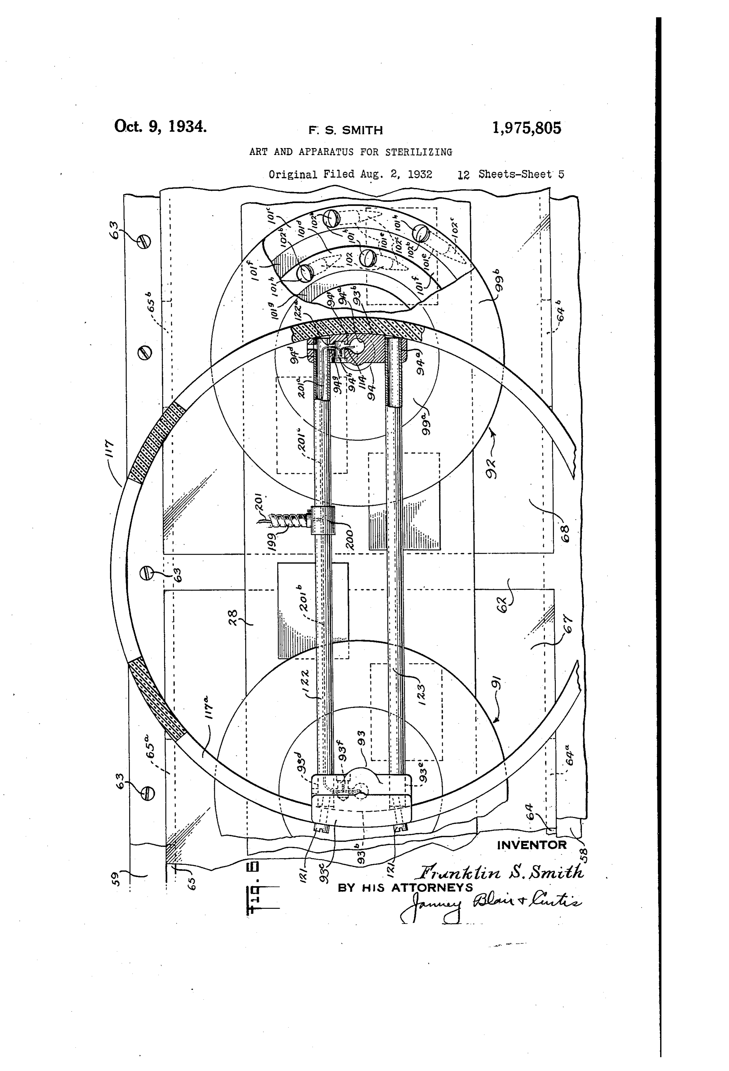
Page 6
Drawing sheet — no readable text.
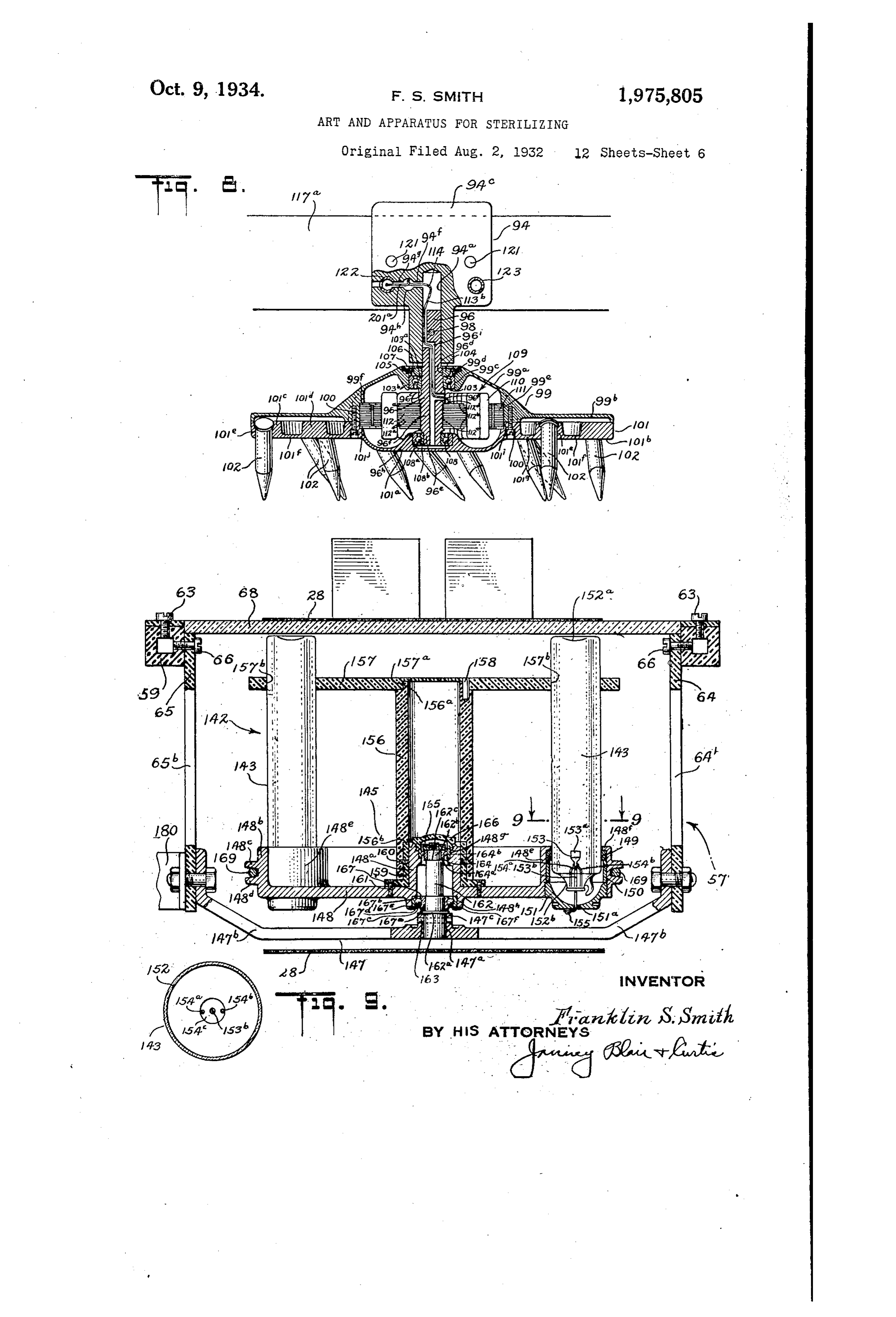
Page 7
Drawing sheet — no readable text.
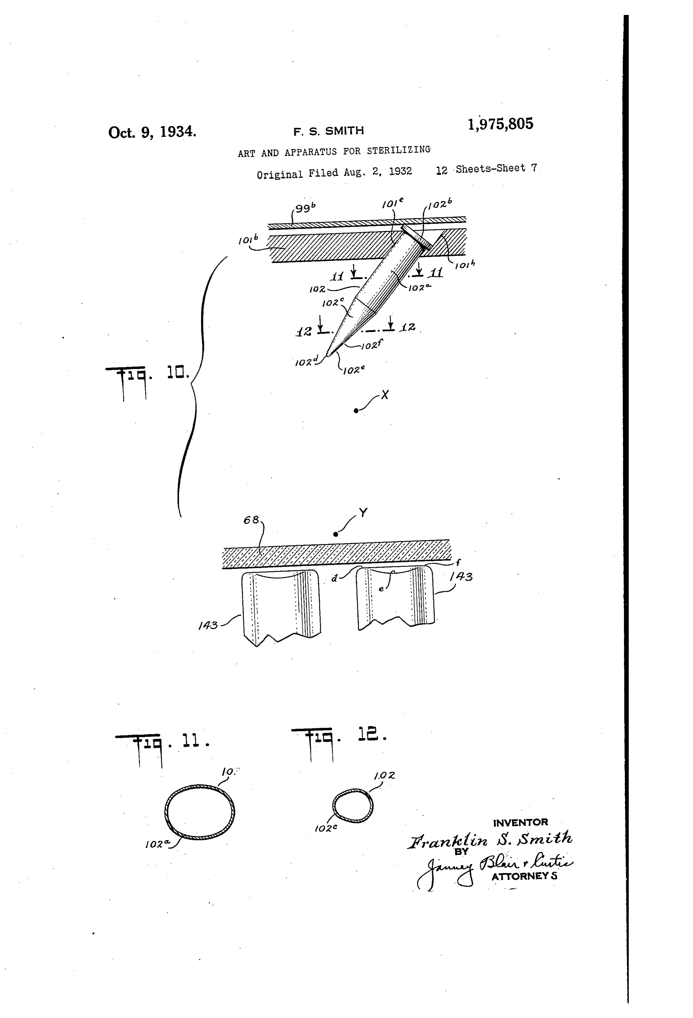
Page 8
Drawing sheet — no readable text.
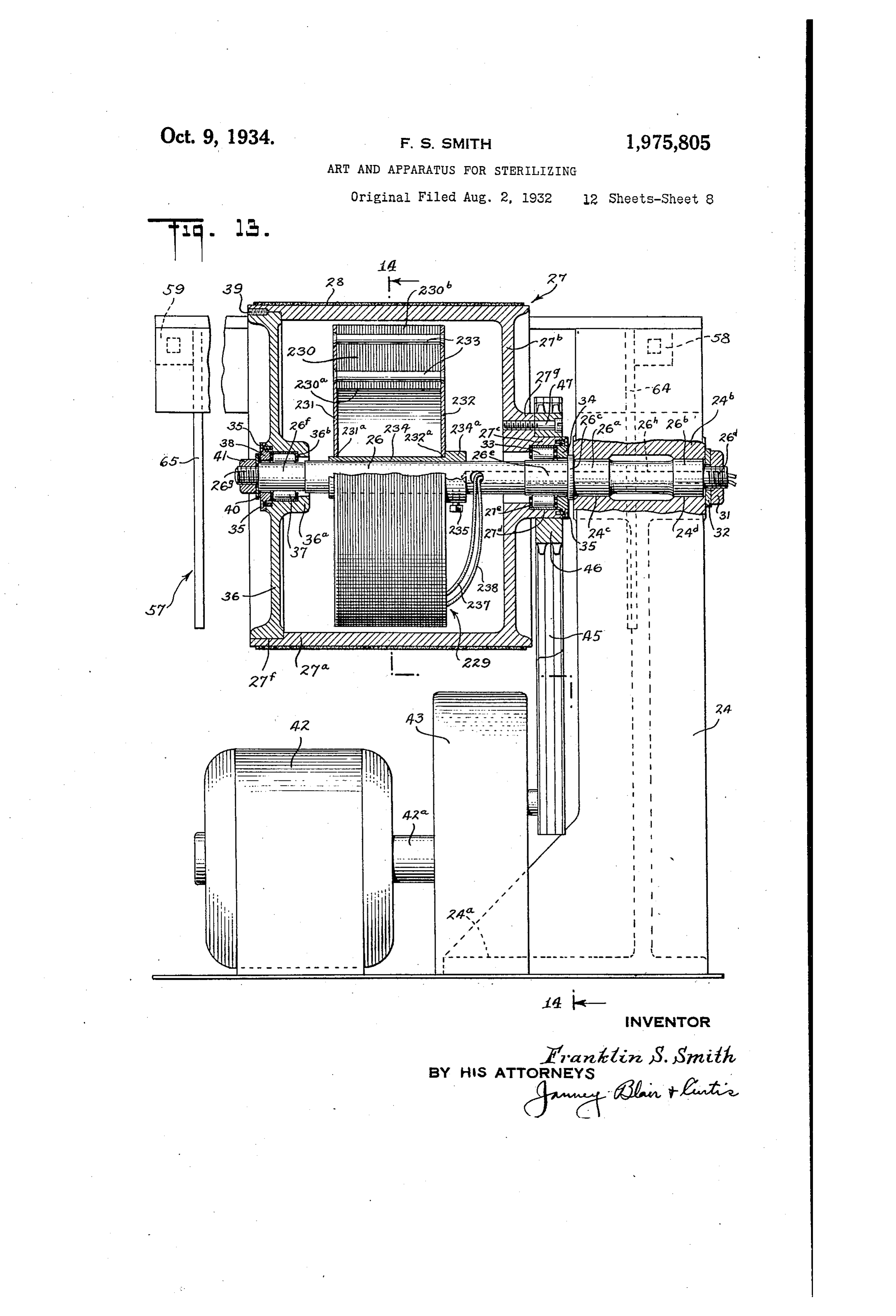
Page 9
Drawing sheet — no readable text.
Page 10
Drawing sheet — no readable text.
Page 11
Drawing sheet — no readable text.
Page 12
Drawing sheet — no readable text.
Page 13
UNITED STATES
ARTE AND APPARATTEUS FOR STAFJERËZLEZINJG.
Franki?tan S. Småbla, Nevy HaySta, COAA,
Application August 2, 1932, Serial Ro. 8 ?291
Remet7ed Teceikatar 23, is33
This invention relates to an art and apparatus Weyor Supporting Structure as See along, te line äCº ºstäº37ing insecº ližeir food and cier prod 4- oš Figure ;
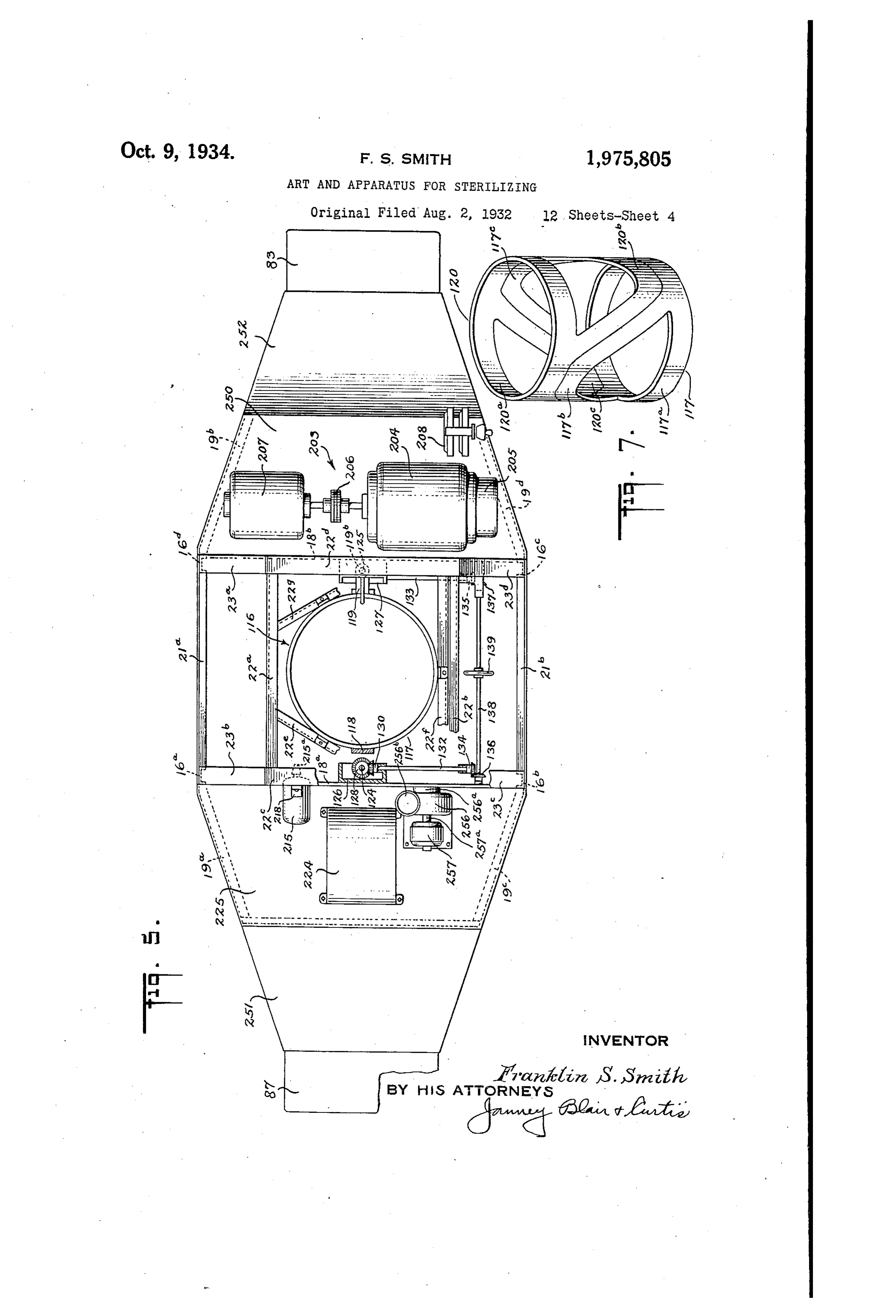
ta:S. figuSe 5 is a plain view of the apparatus, sub Cine of the objects of this invention is to pro-, st32ntially as seen along the line 5-5 of Figure 1; 3 vide E, throughly reliable art and apparatus foi Sigure 6 is a horizontal Sectional view, on an { Suijscting food and other products containing &nlarged scale, of certain featuires of tie inven. i?ASec?S and/or their eggs, arvae and pupae to S, tioºn Substantially as seen ºloºg ühe line 3–6 of Click and deg2ndable treatinent or destroying Sigure ;
Sucía insect iže "7i?khout in any V578y darmaging the Figure is an isometric Viety of 2, piece of insul. 30 product &eated. Another object is to provide lating tubing showing the maininer of producing aI &Fi arad. 22paratus of the above-IIaentioned a portion of the elect30de suggo;ting stricture cž23:8,ýc?s: V7žnich is tyell adapted to be used in con öhere);
junctic: 'ith another food or product-handling :Figue 8 is a visitical cross-sectional view of 2.99&atils, such as packaging and/or wrapping certain parts of tre apparatus, substantially as 5 Yaachines, without decreasing the output of the SeeT) along te line 3-8 of Figure i; other Ynaciaines and without in any Way sacric Figure 9 is a cross-sectional view, on an ein ing 33iciency aid reliacility of treatment as set, larged scale, of an electronic conduction device, £oith 2:073. Another object is to provide an art Substantiall:7 as seen along the line 9-9 of Fig 27ad 3323aius of the 8bove-mentioned character utre 3;
20 is a 7&aich 3, Coughness and reliability of treat Figura i3 is 2, detached elevation view, on an Saent of 320d and other products is assured. Witia enlarged scale, of an electrode member and an I. Inirii LRT of size, Wy?igit andi cost of appara electronic conduction device in cooperating rela t3S. Ainother object is to provide an art and ap tion therevii;h;
paratus of the above-mentioned character which Figure ii is a horizontal cricss-sectional view of is 7&ll adapted to...haindle products of various kinds an electrodie member as seen along the line 11-ii and sizes which lends itself to an ease and depand of Figure 10; 80 ability of control and which is thoroughly soo. Eigre 2 is a horizontal cross-sectional view? proof and Safe. Another. object is to provide as of ine tip portion of an electrode member as art and apparatus of the above-mentioned char Seen along the line 12-12 of Figure 10; acter in which highly efficient and thoroughly re Figure 3 is a vertical sectional view, On 2n 35 liable results are achieved with apparatus of nin enlarged scale, of certain parts of the apparatus inu in size, weight and cost, and maximum de Substantially as seen along the line 13-13 of pendability and Safety. Other objects Will be in Figure ;
part obvious or in part pointed out, hereinafter. Figure 14 is a Vertical Sectional VieW7, Om an The invention accordingly consists in the fea enlarged scale, of certain features of the appa 90 tures of construction, combinations of elements, ratus substantially as seen along the line 4-14 arrangements of parts and in the several steps and of Figure 13; - relation and Order of each of the same to one or Figure 15 is a detached front elevation, on more of the others, all as will be illustratively an enlarged Scale, of a portion of the casing for 40 described herein, and the scope of the application the apparatus including a door by means of
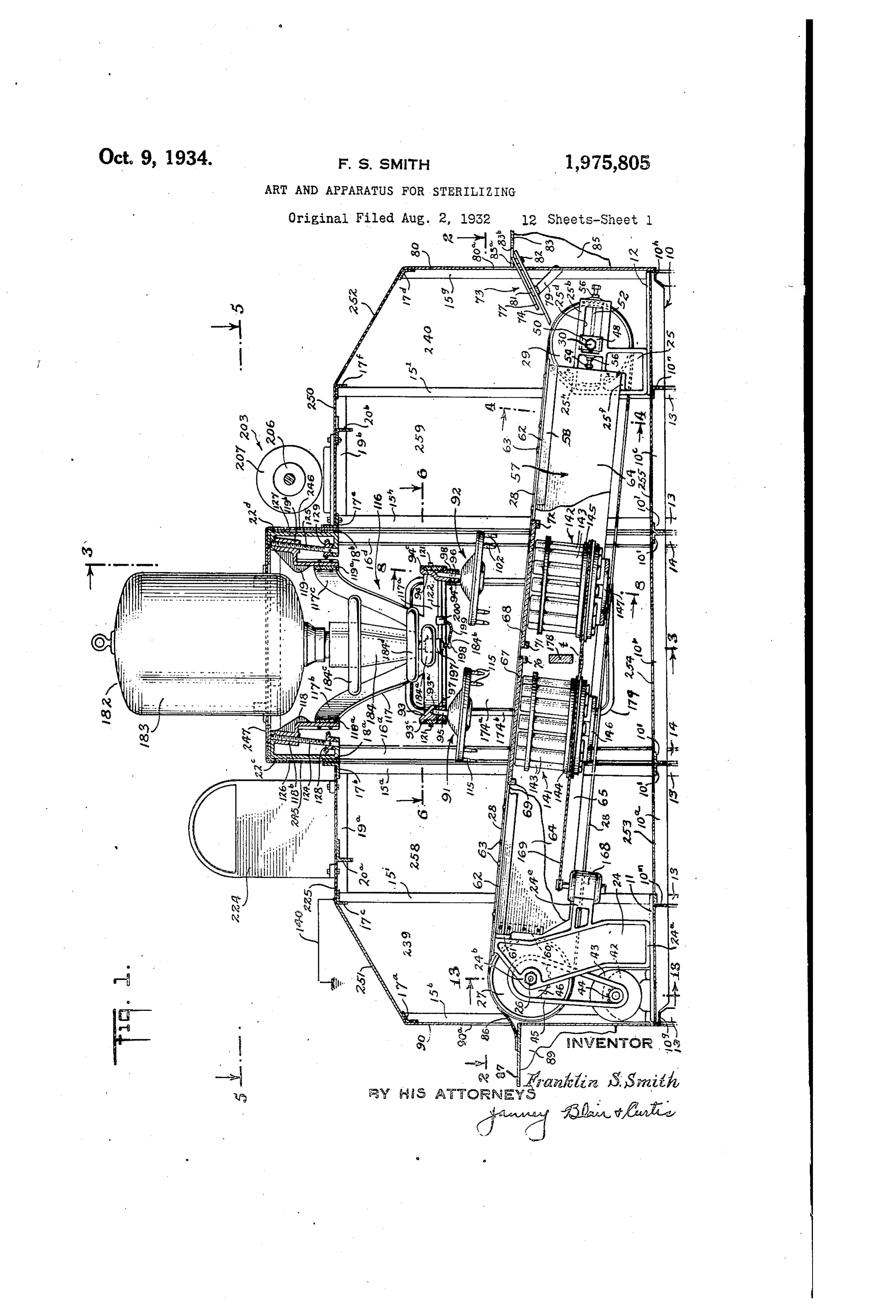
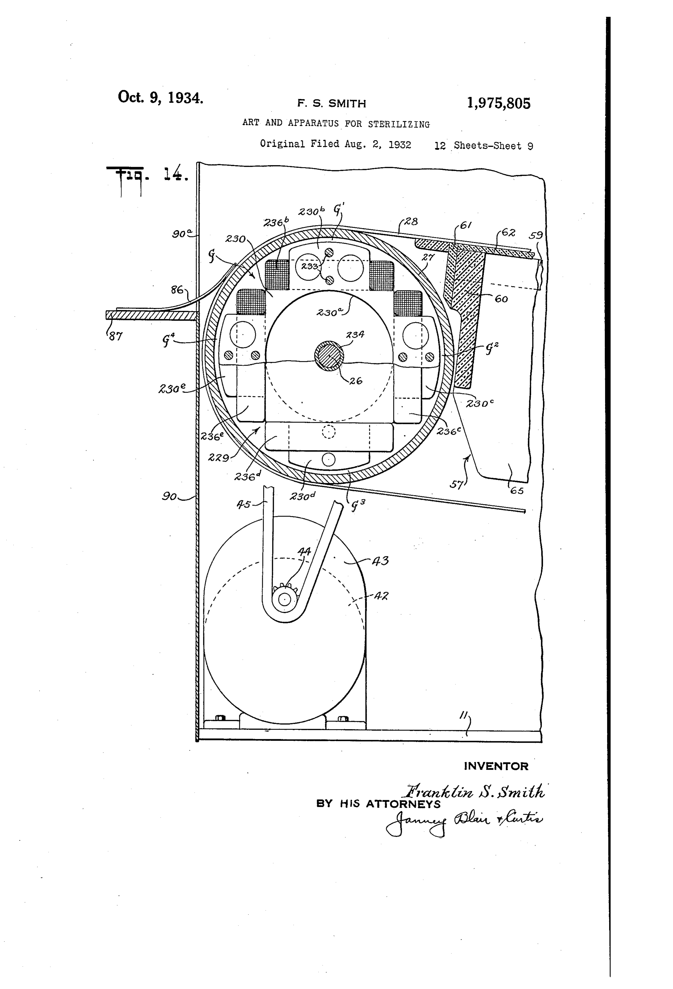
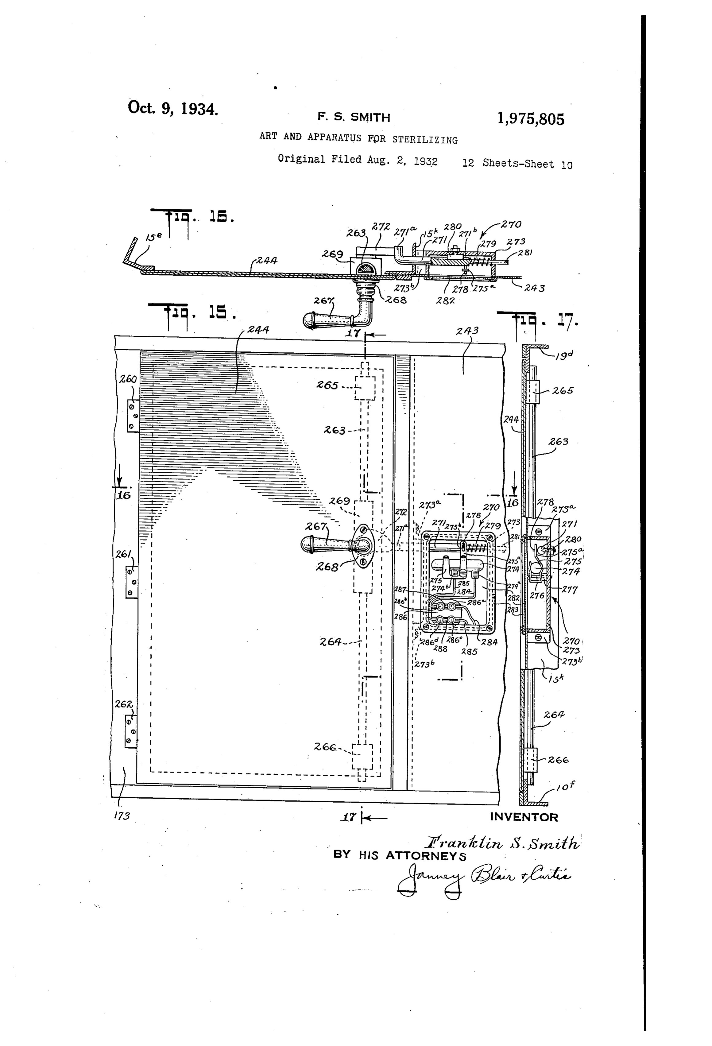
of which will be indicated in the following claims. which access is had to the apparatus; In the accompanying drawings in which is Figure 16 is a horizontal cross-sectional view shown one of the various possible embodiments of a portion of the casing substantially as seen of the electrical and mechanical features of my along the line 16-16 of Figure 15; 45 invention, ? Figure 17 is a vertical sectional viev of a por Figure 1 is a front elevation of the apparatus, tion of the casing Substantially as seen along the 100 certain parts being broken away to more clearly line 17-17 of Figure 15;
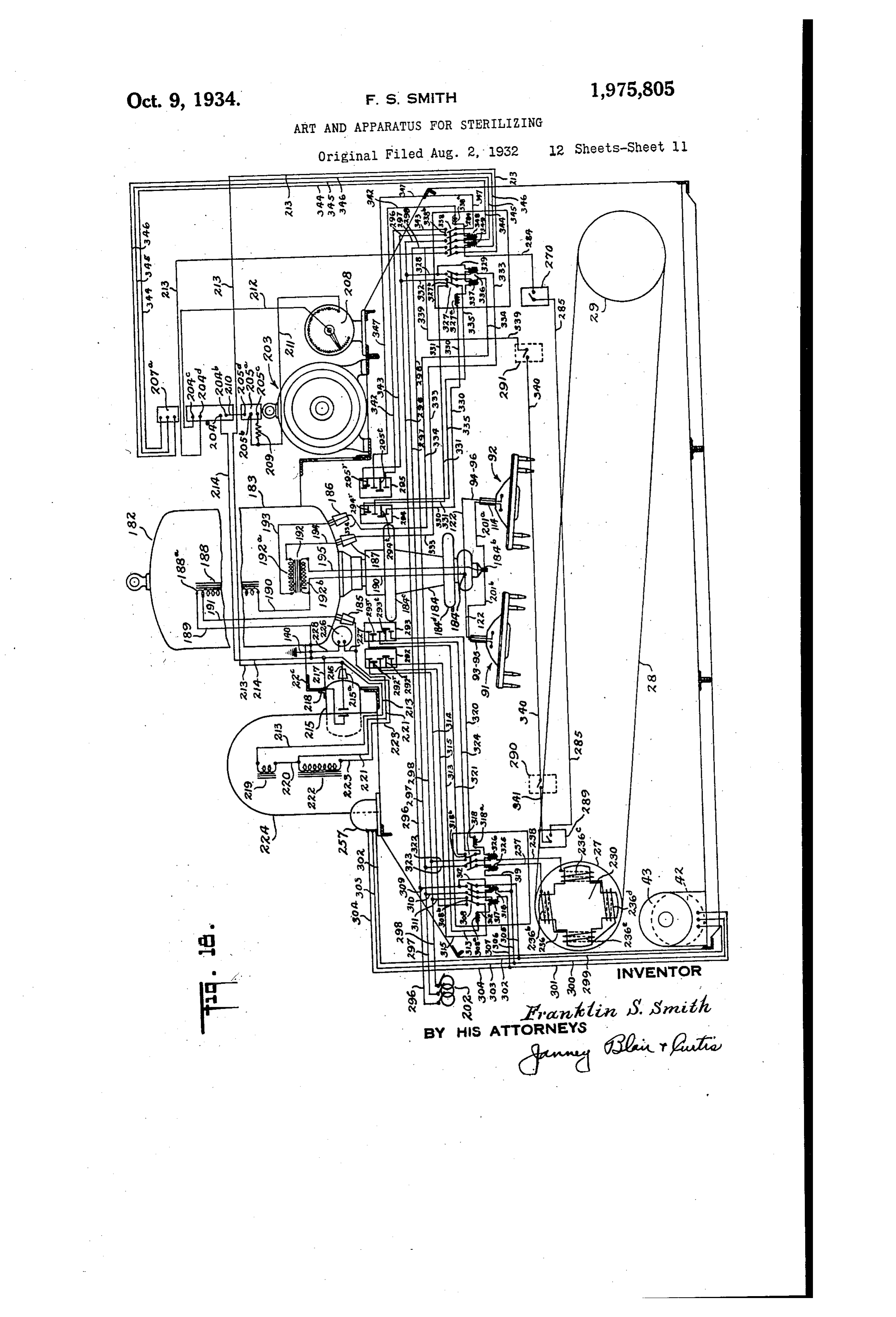
disclose certain features of the invention and Figure 18 is a wiring diagram for the treating other parts being shown in section; apparatus;
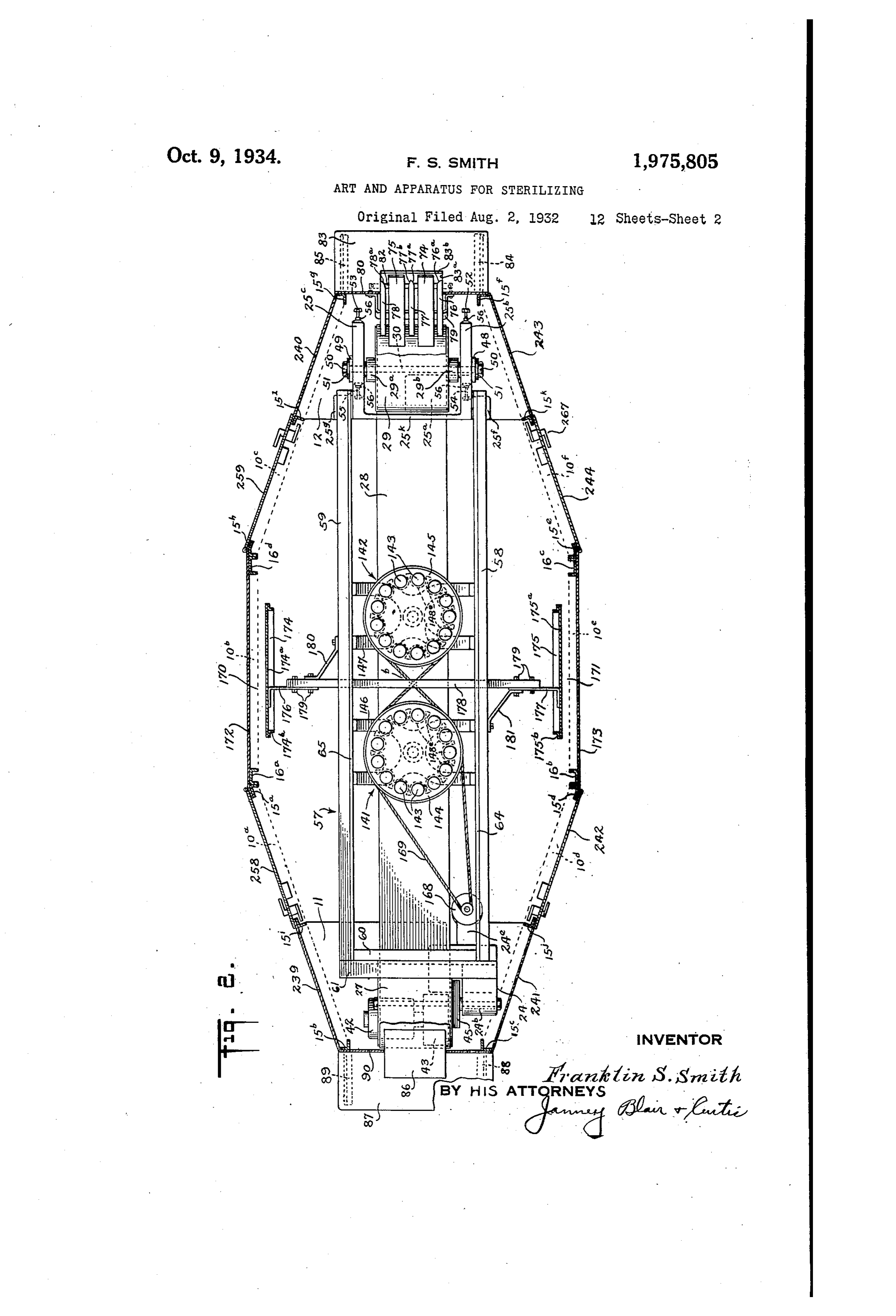
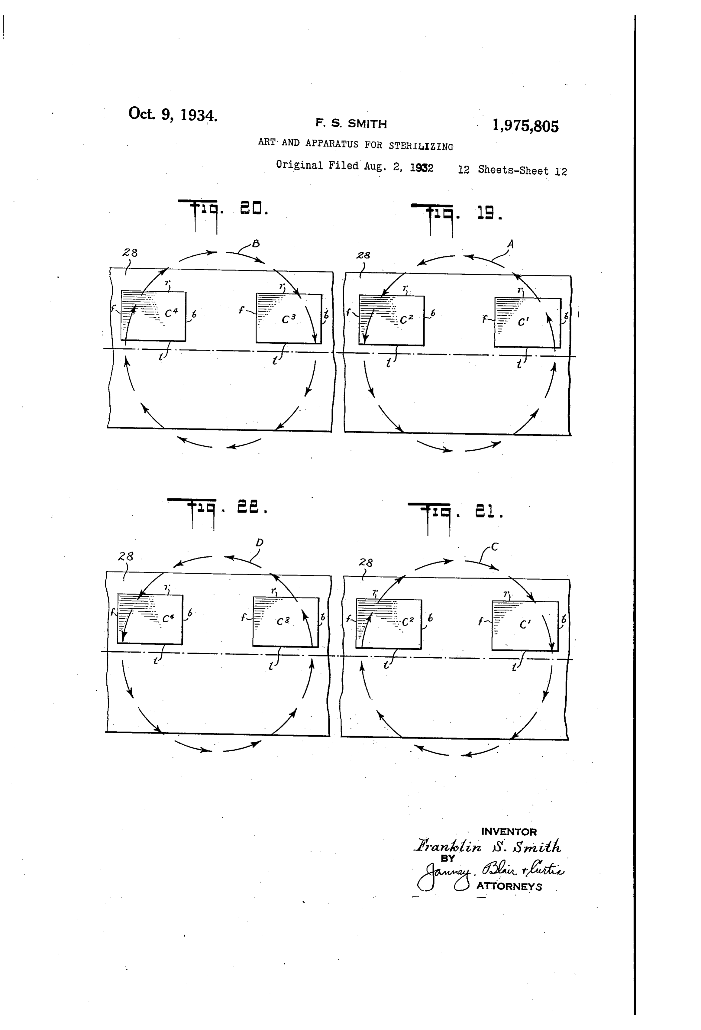
50 Figure 2 is a plan view of the apparatus sub stantially as seen along the line 2-2 of Figure 1: of Figures 19 and 20 are fragmentary pian views 05 the conveyor belt showing packaged products
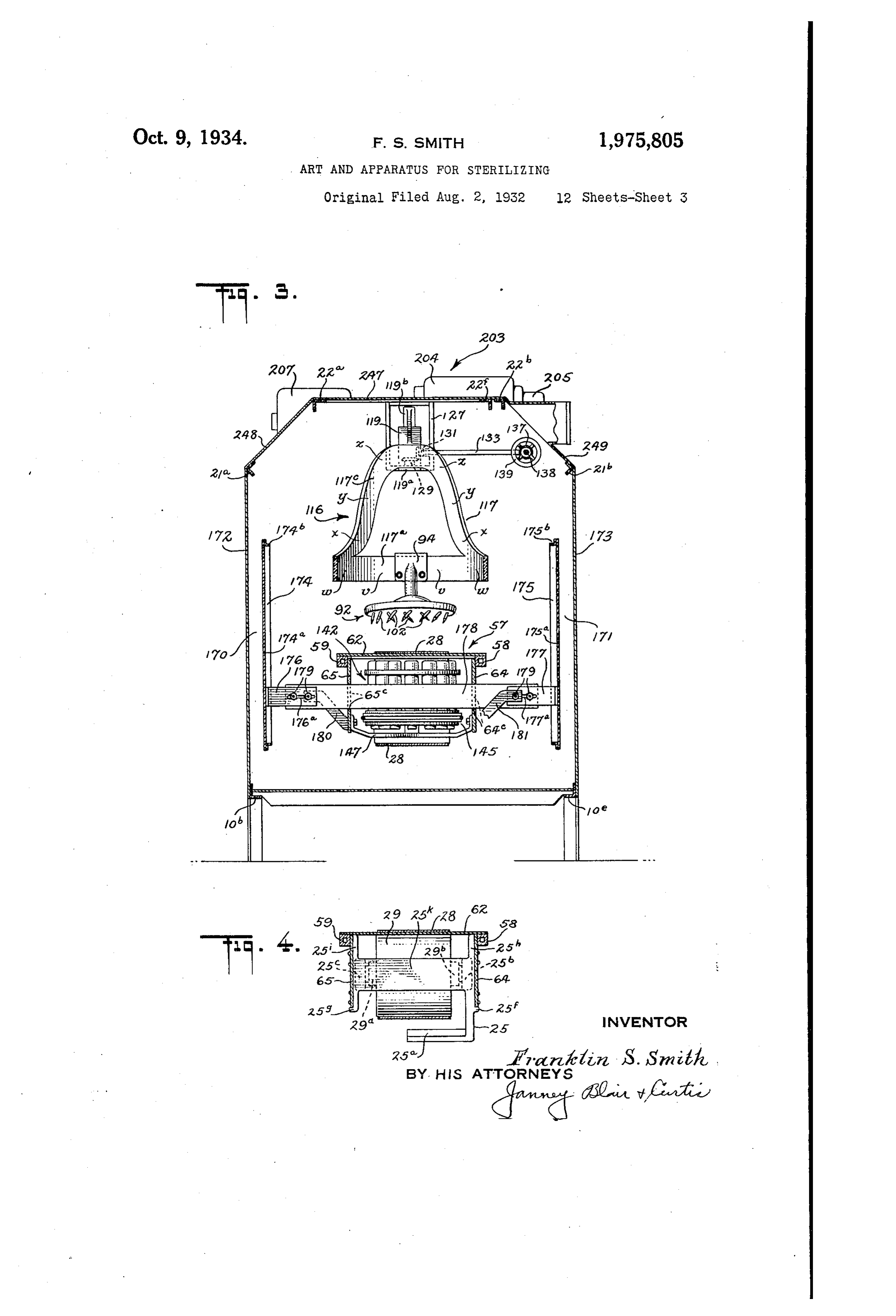
Figure 3 is a sectional elevation of the appara thereon and indicating diagrammatically cer tus substantially as seen along the line 3-3 of tain electrical actions on the packages resulting Figure 1; from the different electrodes; 55 Figure 4 is a vertical cross-section of the con Figures 21 and 22 are fragmentary plan views O
Page 14
of the conveyor. belt showing packages thereon tions 15b and 150 are fastened to the horizontal and indicating diagrammatically certain electri cross-member 17a; the corner sections 15 and 15d to the horizontal section 17b, and the mid cal actions on the packages resulting from the angle-iron motion of the electronic conduction devices. . sections 15 and 15 to the horizontal RO Similar reference characters refer to similar Section 17e. Likewise, the end corner sections parts throughout the several views in the draw 15-158, the corner sections 15-15h, and the ingS. mid-sections 15k-15 are respectively fastened Referring now to the drawings and more par to the horizontally extending angle-iron sections ticularly to Figures 1 and 2, there is shown a iron 17d, 17e and 17. The upper ends of channel 0. Substantially horizontal Octagonal frame 10 pre sections 16a and 16b are secured to the 85 ferably elongated in form and comprising a plu horizontal cross-member 18, and similarly the rality of angle-iron side sections 10, 10 and 10 upper ends of channel-iron sections 16 and 16d and 10d, 10e and 10 with end sections 108 and areRelativesecured to the horizontal cross-member 18. movement between the angle-iron sec 90 10h preferably fastened together as by welding. tions 15 and 15, and between the angle-iron Sec The horizontal frame is strengthened by the transversely extending angle-iron Sections tions 15h and 15 is prevented by the horizontal 10-10 and 10k-10 conveniently welded to the longitudinally extending angle-iron sections 19a side sections 10, 10b and 10, and 10d, 10e and and 19b, respectively, (see Figure 1); in a similar 10. Further strengthening is effected by the manner the angle-iron sections 15-15d and 15e -15k are preserved in proper spaced relation 95.
20 transversely extending angle iron-sections 10 by similar horizontal angle-iron Sections not and 10n, preferably parallel to the end sections 108 and 20h, which are conveniently welded to shown. - the angle-iron sections 10-10d and 109-10, ingSuitably secured to the longitudinally extend horizontal angle-iron sections, as by welding 100 respectively.
25 To the opposite ends of frame 10 are fastened thereto, are cross-members 20s and 20h which the mounting plates 11 and 12 which are prefer serve to strengthen the frame and additionally ably of cast iron and so dimensioned that their serve as part of the supporting structure for cer edge portions are directly supported by the an tain parts of the electrical treating apparatus, all gleafron sections 10s, 10m, 10a and 10d for the as will upperappear more fully hereinafter. ends of the channel-iron sections 105 30 plate 11, and 10h, 10, 100 and 10 for the plate 12. 16aThe and 16d on One side of the skeleton frame The mounting plates 11 and 2 are convenient work are fastened to a horizontal longitudinally ly bolted to the supporting angle-iron sections of extending frame 10 and serve to strengthen the frame as angle-iron section 21 (see Figure 5); well as to present plane supporting surfaces upon likewise, the upper ends of the channel-iron Sec 110 35 which various portions of the apparatus are tions 16b and 16 on the other side of the skeleton mounted, as will appear more fully hereinafter. frame-work are secured to the angle-iron Sec While the horizontal frame 10 may be directly tion 2b.
laid on the shop, mill, or factory floor adjacent A substantially square frame comprising an other machinery, such as packaging or wrapping gle-iron sections 22 and 22, and channel-iron 15 40 machines, fór reasons of cleanliness and econo sections 22e and 22d, preferably welded together my, the frame is preferably supported on legs to form a rigid construction, is Supported in a 13 of angle-iron and additional legs 14 of chan substantial horizontal position spaced above the nel-iron conveniently welded to the frame (seé mid-section of the skeleton frame by the Slanting also Figure 3). To assure firmness and rigidity channel-iron sections 23, 23, 23 and 23d pref 12C 45 of the frame and to prevent creeping along the erably welded to the channel-iron members 22 floor as a result of the vibrations encountered in and 22d of the square frame and to the vertical actual use, the legs are preferably fastened to channel-iron
Spectively.
the floor in any suitable fashion, such as by lag
Screws or by bolts. Extending crosswise of the frame 22-22 125 50 To the Octagonal horizontal frame 10 are 220-22d and substantially tangent at points fastened, as by Welding, the vertical angle-iron spaced are 120° apart to a circle described within the sections 158, 15, 15c, 15d, 15e, 15, 15s, and 15h frame, illustratively three angle-iron Sections Spaced about the octagonal frame conveniently 22e, 22f, and 228 suitably secured to the Square at its corners (see Figure 2) and the additional frame as by welding. The frame-work thus pro 130 vertical channel-iron sections 15, 15, 15k and vided serves to support, in a vertical central posi tion, a part of the treating apparatus to be de 15 preferably spaced intermediate the long sides 10, 10, 10 and 10, respectively. The various scribed hereinafter.
Referring back to Figures 1 and 2, there are vertical angle-iron sections serve as a skeleton frame-work by which the casing or housing for shown at 24 and 25 upstanding Conveyor Sup the apparatus is supported, and they further porting members preferably of a webbed cast iron 135 Serve to support certain parts of the treating ap construction suitably fastened to mounting plates paratus, all as will appear more fully hereinafter. 11The and 12, respectively, by screws or bolts.
support 24 is of a cast iron Webbed con
Additional support for certain parts of the ap paratus is preferably achieved by, illustratively, struction, as above noted, (see also Figure 13) and is provided with a pedestal or base portion 140 four vertical channel-iron sections 16a, 16b, 160 and 16d. which are conveniently mounted adjacent 24a which rests on and is Suitably Secured to the angle-iron sections 15, 15d, 15e and 15h, re thethe mounting plate 11. The upper portion of upstanding support 24 is provided with a spectively, at corners of the frame 10 adjacent its thickened wall portion 24 which is adapted to re 145
3. The various vertical angle-iron and channel 26 upon whichone end of a horizontally extending shaft iron sections are maintained in. their respective is rotatably mounted a driving vertical positions by suitable horizontal trans drum 27 which partially supports and transmits versely extending angle-iron Sections preferably motion to a conveyor belt 28. secured to the vertical Sections by welding. Thus, The conveyor belt 28, is preferably mounted in 50 (Figure 1) the upper ends of the angle-iron Sec an inclined position spaced above the center line
Page 15
of the elongated octagonal frame 10 by driving The driving drum thus tonstructed and ro drum 27 and supporting drum 29 rotataly mounted on shaft 30 which is suitably supported tatably mounted on the shaft 26 is prevented from longitudinal displacement by the raised shoulder by the upstanding support 25. portion 26 on the one end and by a Suitable Considering the driving drum and its asso Washer 40 and nut 41 engaging the threaded end e 3 ciated Supporting structure in greater detail, portion 265 of the shaft 26 on the other end. A (see Figure 13) the supporting shaft 26 is pro slight end play is permitted, however, to prevent vided with thickened end portions 268 and 26b localized Wear of the bearings and shaft; motion which firmly contact the contracted wall gortions toward the right, as seen in Figure i3, being pre 24° and 24d, respectively, of the thickened Wall yented by the outside of the retaining ring 34. portion 24b of support 24. Thus, in effect there Coming up against the shoulder 26, while motion is provided a two point support for the shaft toward the left, as seen in Figure 3, is prevented 26 which enables it to withstand the lateral by the retaining ring 38 conning up against the forces, such as the weight of the driving drun YªyaSheir 40.
5 and the pull of the conveyor belt, without, urdue bending or displacernent. Ifechanical driving energy is supplied to drun 27 by an electric notor 42, illustratively a three
The shaft 26 is provided with a raised shoulder phase induction motor, whose shaft 42, is directly portion 26 which abuts one end of the thickened connected to the reduction gearing 43. Both tine Wall portion 24b of the upstanding support 24, notor 42 and reduction gearing Inechanism 43 are firm contact being assured by nut 31 engaging preferably directly nounted on the mounting a threaded contracted end portion 26d of the plate 11 and are fastened thereto by suitable Shaft, and urging Washer 32 against the opposite Screws or bolts.
end of thickened Wall portion 24b of the up Reduction gearing rechanish 4:3 drives a suit Standing Support. The rigid mounting for shaft able toothed gear wheel 44 (see Figure 14) which 2 26 thus formed serves to maintain it in a horizon transmits notion to a, link belt or chain 45 serv tal position, as above-mentioned, free from aš ing to drive the drun. 27. The Outer surface 200 eral, longitudina, or rotational movement. of the driving drum hub 27.c is adapted to receive Rotatably mounted on the horizontally extendi the toothed. Wheel or Sprocket 46 which prefer ing shaft 26 is a driving drum 27 preferably ably abuts a plurality of projecting portions in . . 30 formed of cast iron with a cylindrical wall por tion 27a and an integral end wall portion 2. tegral with the closed end portion 27b of the The end wall portion 27b is preferably provided driving drum, one of which is shown at 278. The toothed wheel or sprocket 46 is preferably
With a thickened central or hub portion 27c which fastened to the drum by screws 47 threadedly re is centrally bored so as to be received over the ceived in the projecting portions 278 of the drum 35 Shaft 26. The hub portion 27c is provided with end. Toothed gear wheel 44 associated with the an enlarged chamber portion 27d which is adapt reduction gearing mechanism 43 and the toothed ed to Snugly receive the roller bearing assen wheel or sprocket bly 33. 46 associated with driving drun Displacement of the bearing assembly is pre 27 are mounted in Substantial alignment and are mechanically interconnected by link beli, or chain 30 vented by a retaining ring 34, fastened to the 45.
hub portion 270 by screws 35, which urge the ing Thus, upon energization of the electric driv bearing assembly against a shoulder portion 27e hereinafter,42,motion notor in a manner described in Ore fully is transmitted by shaft 42,
Of the hub.
reduction gearing 43, toothed gear 44, link belt
The cylindrical driving drum 27, with its as-, 45, 45 Sociated roller bearing assembly 33, is adapted the and sprocket 46 to the driving drum 27 and to conveyor belt 28.
to be mounted on the shaft, 26 which is provided The speed rating of the motor, the Speed ratio with an accurately machined portion 26e ad transmission of the reduction gearing, the rela jacent the raised shoulder portion 260 which receives the roiler bearing assembly 33 and thus tive sizes of the toothed gear wheels, and the diameter of the driving drum are preferably ali axially supports the driving drum 27 in a po so proportioned that the conveyor belt is driven sition free to rotate. 125 To assure an axial mounting of driving drum at Referring a speed of illustratively 25 feet per minute.
now back to Figures 1 and 2, the Con 27 against lateral forces, such as its own weight veyor belt 28, and the tension of the conveyor belt 28, the in part by the indriving addition to being supported drum 27, as above set 55 cylindrical wall portion 27 of the driving drum forth, is supported by the driven drum 29 which 30 is preferably recessed as at 27f and receives end is preferably cylindrical in form and Substantially closure member 36 in the form of a circular disk. identical in construction
This closure member is preferably provided with driving drum. The driventodrum the above-described is provided with a central hub portion 36a which is adapted to hub portions 29a and 29b (see Figure 2) which in 60 Snugly receive the roller bearing assembly 37. clude roller bearing assemblies by which the drum 135 One end of the bearing assembly is maintained rotatably mounted on the horizontal shaft 30. in firm contact with a shoulder portion 36 of is Shaft 30 is supported by the upstanding sup the hub 36a by a retaining ring 38 which presses port 25 which is preferably of a cast iron webbed against the other end of the bearing assembly;
65 the retaining. ring being fastened to the hub construction having a lower base or foot por portion 368 by suitable screws 35. tion 25, and upper outwardly extending arm 40 portions 25b and 25 interconnected by a flat
End closure member 36, with its associated horizontal portion of reduced section 25k prefer roller bearing assembly 37, is mounted on an ably formed integral tierewith (see Figure 4). accurately machined reduced end portion 26 of The support 25 is p(eferably mounted on the N 0. the horizontal shaft 26. Its outer periphery, as mounting plate 12 and Secured thereto by suit 145 above-mentioned, is received within a recessed able screws or bolts so that the driven drum 29 is portion 27 of the driving drum 27 and is se supported in substantial alignment with the driv cured thereto by suitable set-screws conveniently ing spaced about the periphery, the one end of which tionsdrum 75 is shown at 39.
27. The outwardly extending arms por 25 and 25 of the upstanding support are preferably slotted as at 25d for the arm portion-150
Page 16
25 (see Figure 1), and similarly slotted for the cal rigidity and strength, and conveniently in the arm portion 25e. These slotted portions are form of square tubing, the opposite ends of which adapted to receive the mounting blocks 48 and are fastened to the upstanding supports 24 and .
49 in slidable relation.
The blocks 48 and 49 are preferably provided One end of the parallel beam structure is fas- 80 with central holes which snugly receive opposite tened by suitable screws or bolts to an end-plate ends of the shaft 30 and maintain it in a rigid 60 which in turn is bolted to an angle-iron sec horizontal position; the shaft being fastened in tion 61 mounted in a horizontal position on the proper place by nuts 50 threadedly engaging op upper end of the upstanding support 24 and rig 0. posite ends of the shaft and their associated Wash idly secured thereto by suitable screws. The 85 ers 51 firmly contacting blocks 48 and 49. Nuts other end of the parallel beam structure is Sup 50 are turned up on shaft 30 just sufficiently so ported by the upstanding support 25, in a man that undue longitudinal motion of the shaft is ner more particularly described hereinafter. Beams 58 and 59 serve to slipport the flat elon prevented, nevertheless, permitting the blocks and gated 5 shaft to be slid lengthwise without binding along rectangular sheet of insulating material 90 62, preferably of dielecto or laminated bakelite, the tracks provided by the slotted portions of which is in intimate arms 25 and 25 of the upstanding support. contact with the lower Sur Motion of the shaft with its associated mount face of the upper side of conveyor belt 28 and in ing blocks in a direction lengthwise of the shaft direct supporting relation thereto. 20 is effectively prevented by raised shoulders pro For economical reasons, the upper insulating 95 vided on the outer portions of the blocks which supporting sheet 62 preferably comprises a num contact the outer sides of arms 25th and 25° ad ber of smaller sheets placed in end to end rela jacent the slotted or track portions formed. tion and suitably fastened to the parallel support therein. - ing beams 58 and 59 by screws 63 (see also Figure 25 Shaft 30, and consequently the driven drum 8). To effectively prevent bending of the paral 100 29, may be moved toward or away from the driv lel beams 58 and 59 under the weight of the prod ing drum by adjustment screws 52 and 53 acting uct conveyed by the belt 28, the belt, supporting on blocks 48 and 49 to urge them toward driving structure 57 preferably includes a pair of flat drum 27, and adjustment screws 54 and 55 act elongated insulating members 64 and 65 which 105 30 ing on blocks 48 and 49, respectively, to urge them are fastened in edgewise relation to the parallel away from the driving drum. Each of the Screws beams 58 and 59 respectively as by Screws 66 (see is threadedly received within the arm portions also Figures 8 and 13).
25b and 250 of the upstanding support and are These flat insulating members are preferably secured in their respective positions of adjust fastened interiorly of the parallel beams 58 and 110 59 and afford substantial resistance to the down 35 ment by lock nuts 56. Arms 25b and 25 of the ward bending of the insulating conveyor belt upstanding support are preferably inclined to the horizontal to the same extent as is the upper COn supporting frame. One end of the parallel edge veying Surface of the conveyor belt. wise mounted side members is fastened to the end Thus, as the conveyor belt, preferably of cotton plate 60 by suitable screws, while the opposite 15 or asbestos fabric having sufficient tensile end 40 strength rests upon pedestals 25 and 256 (see also and flexibility to transport the product Figures 2 and 4) formed integrally with the up standing Support 25 and which are preferably to be treated, and of sufficiently high electrical fastened characteristics to withstand the high potential by suitable screws to the broad portions gradients to which it is Subjected, as it Wears and 25h and 25 of arms 25b and 250, respectively of 45 stretches may nevertheless be maintained tight support 25 which contact the inner surfaces of 120 the extreme right-hand ends of side members. 64 about the drums 27 and 29 without changing the and 65. The upper part of the extreme right plane of the belt supporting surface. As the conveyor belt lengthens in use, proper belt ten hand end of the conveyor belt supporting struc sion may be maintained by loosening the adjust ture just falls short of contacting the outer pe riphery of drum 29 in the extreme left-hand 125 50 ment screws 52 and 53 and by tightening up on position of the latter so that as the drum is moved the screws 54 and 55. These adjustments force the shaft supporting blocks 48 and 49 along the to the right to compensate for belt stretch, the slot portion of the arms 25 and 25 to change unsupported length of belt does not get to objec the position of driven drum 29 with respect to the tionable
To givevalues.
a maximumY length of Supporting Sur- 30 55 driving drum 27 and to take up the slack in the conveyor belt 28, all as above-mentioned, without face for the conveying portion of the conveyor effecting a change in the plane of the upper Sup belt, the upper insulating supporting sheet 62 porting surface of the conveyor belt 28. overhangs the main body portion of the Support In order that the upper surface of the conveyor on the right-hand end, as seen in Figure 1, and 60 belt may be maintained substantially in a single just clears the upper portion of the driven drum 185 plane slightly inclined to the horizontal against 29 in extreme left-hand position, while the upper belt sag and the weight of the product conveyed, portion of the angle iron 61 just clears the upper the belt driving tension is preferably placed On portion of the driving drum 27 and effects a result the upper belt side as by rotating the driving similar to the overhanging portion of the insul 40 65 drum 27 in a counter-clockwise direction, as seen lating sheet 62. . in Figure 1. While an insulating supporting sheet of uni Further assurance that the upper surface of the form characteristics may be used to effectively conveyor belt is maintained in a single plane is support the conveyor belt, the mid portion of the achieved by the electrically insulating conveyor belt supporting structure generally shown at 57. supporting away at two sheet or conveyor frame top is cut 145 points spaced along the length of
This supporting structure preferably comprises a the conveyor supporting structure and replaced pair of parallel insulating supporting beams 58 by substantially square plates and 59 preferably of a material, such as laminat material, such as Pyrex glass oforsolid dielectric ed “Bakelite or Dielecto,' having high electrical 67 and 68, the purpose of which willfused quartz, appear more 15 75 resistance characteristics coupled with mechani
Page 17
Drawing sheet — no readable text.
Page 18
shaped pins 97 and 98 passing through suitable tip portions 102d of the various electrode members holes provided in bracket 93, stem 95, and lie along two concentric circles and preferably bracket 94 and stem 96, respectively. in a common plane.
For reasons of economy, as will appear more Electrode 92 is preferably rotated, in a man 80 ner to be more fully described hereinafter, in 5 fully hereinafter, the brackets 93 and 94 are such preferably mounted on a horizontal frame form a direction that the upper head portions of ing an acute angle with the common plane of the the electrode members are leading with the ex electrode members 91 and 92. treme tip portions trailing; for the electrode 92 In order that the electrodes 91 and 92 may be the rotation, as seen looking down on the elec 85 10 firmly and rigidly supported by the bracketS 93 trode (see Figure 6) is in a counter-clockwise and 94, respectively, the brackets are preferably direction. An individual electrode member (see of unsymmetrical construction the one, 94, Figure 10) illustratively moves in a direction being of an increased length since it extends from left to right with its upper portion leading across the wider portion of the above-mentioned and with its lower tipº portion trailling. A hori 90 5 angle between planes. Similarly, the stem por ZOntal Section taken through the main portion of tion 96 of the electrode 92 associated with the the electrode member (see Figure 11) is elliptical longer bracket 94 is preferably of an increased in form and through the tip portion substan length to give added rigidity to the connection tially egg-shaped in form (see Figure 12) thus with the longer bracket. giving a substantially stream-line construction 20 Electrode members 91 and 92 are preferably of to the slainting electrode member which effects 95 a minimum disturbance of the ambient air, the analogous construction for reasons of manufac desirability turing economy so that a detailed discussion of of which will appear more fully here but one of the electrode members 92 will now be in after in considering certain electrical actions given. of the apparatus, as the electrode is rapidly ro 25 Referring now more particularly to Figure 8, tated as indicated above. 100 there is shown at 99 an inverted dish-shaped While various numbers of electrode members housing preferably of cast aluminum, having may be used in the construction of an electrode high electrical conductivity, with a central depending upon the diameter of the rotatable humped body portion 99 and a flat rim portion electrode, the number of rings of concentric elec 105 30 99?. trode members, the size of electrode members, Fastened to the inverted dish-shaped housing and the spacing between them, I conveniently 99, by suitable screws 100, is a dish-shaped employ electrode members spaced from each other -housing portion 101 also preferably of cast in a circle so that their projected lengths are aluminum having a central downwardly extend approximately equal to the distance between 110 85 ing body portion 101 and a flat outwardly ex these projections.
tending rim portion 101b. The diameters of the illustratively two concen The outer rim portion 101b of the lover por tric circles in which the electrode members are tion of the housing preferably includes two Con arrayed are preferably Such that the projection of centric thickened ring portions 101 and 101, the outer circle falls beyond both edges of the 409 each of which are provided with spaced hole por conveyor belt 28 (see Figure 6), while the pro 5 tions. 101e (see Figure 6) in an alternate or stag jection of the inner circle overlaps and just falls outside of the path of travel of the packaged gered relation which are adapted to receive elec product or articles to be treated; the diameter trode members 102. Between concentric thick of the latter circle is preferably slightly greater ened ring portions 101 and 101d of the rim 101 than the width belt, while that of 120 45 is a relatively thin interconnecting section 101, the smaller circleofis conveyor and similarly between the inner thickened ring For a conveyor beltslightly less. of about 14 inches in width, portion 101d and a central downwardly extending body portion 101a is a relatively thin intercon the Outer ring of electrode members is about 16 necting section 101g; this construction makes for inches in diameter including illustratively 9 elec 50 a saving in material yet permits adequate mount trode members of 4 inches in length spaced 40° 125 ings for the electrode members 102. apart, while the inner ring of electrode members The various electrode members 102 are pref is about 10% inches in diameter including illus erably of identical construction comprising (See tratively 9 electrode members 4 inches long Figure 10) a main cylindrical body portion 102, spaced 40 apart and alternating with the elec 55 an upper flat circular head portion 102, and a trode members of the Outer ring. lower conical sharp tip portion 102°. The va The various highly polished, illustratively rious electrode members are preferably made of nickel-steel, electrode members are removably nickel steel tubing worked into the form indicated positioned in the various above-mentioned holes and highly polished, particularly adjacent the provided in lower portion 101b of the electrode 33 housing and so held that their various flat head 60 extreme tip portions thereof, to give smooth un portions 102b are Snugly received within counter broken surfaces free from irregularities and sunk portions 101h (see Figures 6, 8 and 10), by small projections; the advantages to be derived contact with the lower surface of the flat rim from this construction will appear more fully portion 99b of the upper portion of the electrode hereinafter. housing; upper and lower portions of the housing 40 The various hole portions 101e arranged in two being held in assembled relation by screws 100. concentric rings about the concentric ring por With this construction the various electrode . tions 1010 and 101d, respectively, of the lower portion of the housing, are preferably inclined at members may be removed and replaced by other a common angle of 50° or 60 with respect to the electrode members of the same kind or by elec trode members of a different kind, longer or 70 plane of the electrode; the center lines of the shorter, holes and consequently the center lines of the with the extreme tip portion sharper or various electrode members individually associated amore blunt, or of a different material, all with with the holes lie in planes substantially tangent minimum disturbance of the other portions of to either of the two concentric ring portions of the apparatus. Furthermore, such a construc 5 the lower electrode housing. Thus, the extreme tion gives a good firm support to the various elec- 15
Page 19
trode members which in addition is well adapted 11 associated there with nounted Oil housihg to transfer the heat produced at the tip portions 99-0.
of the electrode members to the body of the elec The field 110 preferably includes a laminated trode where it is readily dissipated; the construc iron core 32 illustratively conprising 3, stack of tion is also of high electrical conductivity and individual light in weight, all of which makes for a high circular endcircular disks of suitable iron ii.2, and 33 plates 1.2b of an appreciably thicker opera?ing efficiency and an economy in manul iron. The core is providied With a centrai hole facture. portion 12c which receives a reduced portion 96 The electrode housing 99 with its associated of the shaft; the core is pressed onto the shaft iO alectrode embers iO2 is rotatably mounted, as indicated above, on the shaft 96, the upstanding prior to the assembly of the electro?e until the 3.5. upper end plate 112º abuis a, shoulder portion 968 or ster end of which, as above-mentioned, is Of tine skafi aftSr vVinicin ine Snd Of the reducedi suitably secured to bracket 94.
Shaft, 96 is formed with a central expanded por section 96 is intshrcorned as ait 96h to press tion 968 and with an adjacent, narrow portion 96 laxinatedthecore against lov7er end plate i52b and hoids the which snugly receives the inner race i03 of the On the shaft. in a cozing)act asseinoled relation 3 ball bearing assembly i03.
The lower end of the inner race 1638 of the bail andthe outei periphery oš the core ii.2 is slotted haaring assembly firmly abuts a shoulder portion pole windingwith wound the illustratively single pin2S3 6 980 of the shaft between the expanded and in Ore Se forms o part ofSince
the presen? invention, I., de 5 reducei sections 962 and 969, respectively, and is tailed
Reld in firra abutting relation by the retaining ring One description
of it will ino, be given.
the Windig is rought out, aid i04 threadedly engaging the shaft as at 93; thus, grounded to the core as iš 132, Vižinie the cier he ball oearing asseinoly iC3 is secureiy Yaouinted end 113b is tal:eYa Ug througin B, Caaílínei B ? is in3 shaft 96.
ihe upger portion 998 of the electrode housing is provided with a central hole portion 990 of thick with oracle, 94.
Wall construction adapted to snugly receive the 2,2137 spa,33d 23C13i ?33 ield outer race iC3b of the ball bearing assermoly.
The upper part of the hole portio provided in the ugpa part of the electrode housing is of 8, similiar diazmeter so as to provide a sihoulder 990
Vinici rests tipon the Uppe’ end of the Ot?e?' 'ace :03d O? the ball be2}ºi:1g aSSe:mbly. ºlls, ie eiec
:3Spectiva 31? igº73 portions o 0ile iad li:Siúg.
teec'de NGLISEig is
9? of the t; pºtei" portion of upon the feit vasher 195; piaise a:
17&sine: are secux'3d to the iO2Sing oy Suitable.
5 scr'3' is 'i'. Dust plate 3 S is preferably SO znolišed 23. ing otº table celi Fijke Saif? 98 a. ši iÈS 33S tio de ring or nuš, 404 to aiiovy Sree rotation of the elec šios O ?te 1 örode.
O ASSUS AN akiai I'otition. f tie electrode 92 housing rapicily t':33Siet tiag :gat, produced in 2) the Toto" cole ed 7idings Ka?, pertially giY7e and central part up ?t hae electrode housing is to the air enclos?d yithin time housing) to the recessed as ai, 101 h and Sugiy receives the outer isCiter Suicace of ne electro?ie nousing Wiere iò rapidly COAnducted away or dissipated by the race portion 08 of the ball 382,ing a SSerbly i03, anoient air througi, viiich the electrode housing the inner race 108b of which is pressed onto a, rotates upon energization of the induction notor reduced end section 98° of the Sinait. EuS, elec trode housing 99-191 with its associated elec in 109, in a nanner more particularly described here irode inerinbers i02 is a:ially supported on shaft aftei, illustratively by Way of conducto 234 and 96 and adapted to be rotated about its ceintral axis theMiechanical metallic bracket 94, shaft, 96, and Sied core 12.
driving energy is in parted to hous
With a mininum frictional resistance in the bear ings and ininimum windage in pedance (due to ing 99-10 and the associated electrodie Kanembers 112 causing tinæ latter to V7iair along ?ineir pre
the effective stream-line constZuction of the vari scribed circula, pašhs in a counter-ccclgWise di ous electrode members).
Driving energy for rotating the electrode hous rection, 2.S | 2bove-meintioned, at 2, Speed of ap ing 99-101 is preferably supplied by a single proximately. 4500 feet per minute for the outer phase alternating current induction notor gen ute for the innermembers, ring of electrode and 3000 feet per min ring for the dimensions illus erally shown at 109, rated illustratively 220 volt, tratively given above.
6 pole, 60 cycle with a synchronous speed of 1200 Electrode 91, as above-mentioned, is analogous R. P. M., preferably including a stationary field , 110 mounted on shaft 96 and 2 rotating are nature in construction to electrode 92 with these differ ences, novever; the induction motor associated lºº
Page 20
with electrode 91 drives the latter in a clockwise the insulating support are secured to metallic direction and accordingly the electrode members brackets 118 and 119, as mentioned above, the lower edges of the extreme upper portion of the 115 associated with this electrode are slanted in an opposite direction to those associated with the loops 117b and 117 resting on toes 118 and 119a, respectively, preferably made integral with the 80 oppositely rotating electrode 92, with their ex respective brackets li8 and 119; insulating Sup treme tip portions in a trailing position, in Order to realize the stream-line effects mentioned above ports and brackets are preferably bolted together in the consideration of the action of electrode 92. to give a rigid and Secure fastening Well adapted Electrodes 91 and 92 are rotated in opposite to withstand twisting or turning about the hori 85 O directions with the extreme tip portions of their zontal axis as a result of lateral stresses acci respective electrode members whirling in, pref dentally applied to either the electrodes or their erably, a common plane spaced above and Sub Supports.
stantially parallel to the upper conveying Sur Brackets 118 and 119 are provided with offset face of the belt 28. These electrodes are adapted threaded upper portions 118 and 119b, respec 90 5 to be maintained at a high electrical potential, tively, which are slightly inclined to the vertical illustratively 150,000 volts with respect to ground, by an amount equivalent to the incline of the Con the manner and purpose of which will appear veyor, or in effect substantially perpendicular to more fully hereinafter. w the upper conveying surface of the conveyor belt Electrodes 91 and 92 are maintained in Spaced 28. To give a free and unencumbered mounting 95 20 relation above the conveyor belt 28 in the manner for the electrode supporting structure, brackets indicated by the electrode supporting structure 118 and 119 are offset Outwardly, the One 118 be generally shown at 116 (see Figure 1) which pref ing offset toward the left, as seen in Figure 1, erably includes an insulating framework 117 which while the other, 119, is offset toward the right is supported by metallic brackets 118 and 119. where they respectively engage parallel threaded 100 25 Insulating support 117 (see Figure 7) is pref shafts or elevation screws 124 and 125 rotatably erably cut from a large tubular piece of insulating mounted in C-brackets 126 and 127, respectively, material, such as dielecto or laminated bakelite, perwhich in turn are illustratively welded to the up having appreciable mechanical strength in addi and lower horizontal iron frame sections tion to its high electrical insulation characteris 229-18s and 22d-18, respectively. 30 tics in the form indicated. From a single short C-brackets 126 and 127 are preferably so con 105 length of tubing, two such insulating Supports 11 structed that elevation Screws 124 and 125, re and 120 maybe conveniently cut having ring por spectively, journaled or rotatably mounted there tions 1178, and 1208, respectively, and loop por in are maintained perpendicular to and in Sub tions 117b and 117 and 120b and 120°, respec stantial alignment with the upper part of the tively, located on diagrammatically opposite sides conveyor belt 28 and consequently in substantial 110 of the respective ring portions 117 and 120. parallel relation with the axial mountings of elec Thus, two individual insulating supporting mem trodes 91 and 92.
bers are obtained from a minimum length of in Elevation.screws 124 and 125 respectively are sulating tubing with a consequent saving in ma adapted to be rotated by bevel gears 128 and
terial and a reduction in the cost of manufacture. 129 which are suitably fastened to the lower ends Referring now back to Figure 1, the insulating of the respective screws illustratively by suitable supporting member 117 is preferably mounted Sym. pins (not shown). Mieshing with bevel gears 128 metrically about a vertical axis with its ring por and 129 are bevel gears 130 and 131 (see Figures tion 117a lowermost and Substantially horizontal 3 and 5) Suitably fastened to horizontal shafts 45 about which are mounted, at diagrammatically 132 and 133, respectively, illustratively journaled 120 opposite points, metallic brackets 93 and 94. in the associated C-brackets 126 and 127 and Brackets 93 and 94 (see Figure 6) are prefer the horizontally extending angle-iron Section 22b. ably provided with convex curved upper portions Shafts 132 and 133 are rotated by bevel gears 93b and 94b, respectively, which are adapted to 134 and 135, respectively, co-acting with the re 125 50 contact the inner curved Surface of the ring por Spective bevel gears 136 and 137 Secured to hori tion 117s of the insulating support. Brackets zontal shaft 138, the ends of which are conven 93 and 94 are further provided with Over-hang iently journaled in the horizontal transversely ing lip portions 930 and 94° (see Figure 1) which extending frame sections 18 and 18b. squarely rest upon the upper horizontal edge of . Upon manipulation of handwheel 139, suitably 55 the ring portion 117a of the insulating Support 130 mounted on shaft 138 and fastened thereto by a which thus sustains a good portion of the weight Set Screw or pin, a change is made in the posi of the electrodes and furthermore prevents dis tion of electrodes 91 and 92 with respect to the placement of electrodes and metallic brackets upper conveying surface of the belt 28. For ex about a horizontal axis; the brackets are fastened upon rotating handwheel 139 in a clock 135 to the insulating support by suitable screws 121. ample,
To prevent bending, twisting or warping of the wise direction, as seen from the left of Figure lower horizontal ring portion 17s of the insulat 5 looking along shaft 138, and consequent rota ing support, there are provided a pair of parallel tion of shaft 138 and its associated gears 136 and
tubular conducting compression members 122 and 137, there is imparted, through the respectively 140 123 (see Figure 6), the ends of which are snugly associated gears 134 and 135, a rotation in a clock received within suitable holes provided in brack wise direction to shafts 132 and 133, respectively. Rotation of horizontal shafts 132 and 133 with
Holes are provided at 93d and 94d to receive op their respective associated gears. 130 and 131 co posite ends of the conducting tube 122 in brack acting with gears 128 and 129, respectively, gives 145 ets 93 and 94, respectively, and similarly holes a clockwise rotation of the respective elevation are provided at 938 and 949 to receive opposite screws 124 and 125, as seen in a direction looking ends of the tubular member 123 in the respective downwardly an assumed along the length of the screws. For right-hand threaded engagement brackets 93 and 94.
75 The upstanding loop portions 117 and 117 of between elevation screws and brackets, electrodes 150
Page 21
and Supporting structure are then raised into , Weight is achieved with a consequent saving in position illustratively shown in Figure . material and economy in manufacture. The ex In an analogous fashion manipulation of hand tent of the reduction in over-all height and pro Wheel 139 in a counter-clockwise direction, as seen from the left of Sigure 5 looking along its portionate cí electrode increase in the rigidity and stability raounting is gained by comparing the 30 associated shaft 138, lowers electrodes into 2 posi Selatively short tion aearer the upper surface of conveyor belt. of bracket 94 andstraight-line path between top Thus, by Gnanipulating handwheel 139, a precise length of path along the surface of19insulating bottom of bracket with the
Setting of electrodes 9 and 92, and more particu SLipport i 17 through points v, uv, ac, y and g. larly the extreme tip portions of their associated Cooperating with the electrodes 9 and 92 and 3.5 electrode members ii.5 and 112, respectively, Spaced immediately beneath the upper part of above the upper conveying surface of belt 28, is Conveyor belt 28 and the insulating sheeting 62 achieved.
of the conveyor belt supporting structure 57 (Fig it inay at this point be noted that, as the elec ure trodernembers are raised or lowered into positions right1) cylinders are arranged preferably in time form of Wo
(Sigure 2) 343 and 42 substan
Rore remote front or nore adjacent to the coin tially coaxial with the electrodes 95 and 92, re Weyor, the motion is purely translatory in a direc Sgectively, a Suitable nuancer of preferably iden ?ioRn perpendicular to the upper conveying su3rface of the belt; the raising or lowering of the elec tical electronic conduction devices 343. The ex 2 isodes is effected without changing their positions reize Outside diameters of ine Gyinders 43 and either longitudinally or transversely of the con i£2 ošequal electronic conduction devices are prefer Weyor. A Rurnber of the particular advantages siliy to or slightly less than the diameters of the circles traced by the extree tip portions derived from this construction will appeak fore of zie outer rings of electrode members 115 and fully hereinafter in considering certain electri 25 cal actions and co-actions of aid between the 2.92, respectively, as they are Whiled above the c0nYyeyo" (see also Figure G), Yº?hiie the inner di 00 various parts of the apparatus aereign afte: de anetter
Scribéd. of the cylinders cf electronic conduction devices (as determined by the extreme diameters
Hardvineel, elevation screws, headed oracizets 200ve inentioned ieSS twice the cross-sectional and their associated interconnecting shafting and 30 gearing are all for reasons of Saifety, convenience vºyidtka oštine individual electronic devices compris ising the cylinders) are substantially equal to or and economy in direct mechanica and electics greater than the circular paths traced by the ex 05. connection with the iron supporting fra Cnework which is preferably maintained at, ground poten treme tip poitions of the inner rings of electrode inenbers i5 and 102 on rotation of electrodes tial as diagrammatically indicated at 40 9 and 92, respectively.
Preferably, the electronic conduction devices
Flectrodes 91, and 92, es above indic&se, are 2.43 are in the form of elongated cylindrical tubes. maintained at a high electrical potential via of diagnette's Substaitially aqual to the distance respect to ground. Insulating Sugporting raea between the inner and outer rings of electrode ber 17 not only maintains the electrodes ix. Inerne's 5 and 102, and of such length that spaced relation above the conveyor, out, also main they are adapted to be conveniently received with tains the electrodes at high electrical potential in the space betv/eSI). Upper and lower Sides of 5 with respect to the grounded brackets and frame belt 28; illustratively the length is five or six times which
in turn support the insuleting member the diametes.
45 The various electronic conduction devices i43 Togive a firm andi riigid supporº for the elec are maintained in cylindrical groups 141 and 42 trodes and at the same time to maintain thern at spaced from electrodes 91 and 92 respectively, as their high electrical potentials, all without undue indicated above, by suitable racks 144 and 14.5 Over-all size and . Weight of insulating naterial, and their associated supporting yokes 146 and the Support 117 is cut in the form and manner 50 described above and illustrated in Figured to give 147, respectively, preferably bolted to the side Wall portions 64 and 65 of the conveyor belt Sup 25 a long electrical leakage path from the high po porting framework 58 (see Figure 2). tential electrodes to the grounded brackets. or reasons oi siplicity and economy of con Electrodes 91 and 92 are mounted by their-asso struction, the cylindrical groups i41 and i42 of ciated metallic brackets 93 and 94, respectively like electronic conduction devices 143 and their 55 (see Figures 1 and 3) at diagrammatically ippo associated supporting structures 144-146 and 30 site points on the ring section 117s of the insul 145-147 are preferably identical So that but the lating support intermediate the junctions Gf loop one group 142 and the Supporting structure 45 portions 117b and 117c with ring portion 117a. 147 is considered in detail,
The path for the leakage flux for electrode 92 Referring now more particularly to Figure 8 69 and its associated bracket 94 (see Figure 3) is there is shown at 145 a circular rack preferably along a portion of the ring 117, through points rotatably mounted and including illustratively a 35. and U, then along both curved arms of the loop flat dish-shaped cast aluminum base 148 having 117, and through points ac, gy and 2 to grounded a central hub portion 148 and an Outer upturned bracket 119. Likewise the leakage flux from elec rim portion 148, the Outer periphery of which is trode 91 and its associated supporting bracket 93 provided with raised circumferential sections 148 40 maintained at high potential to the grounded and 148d to form a sheave, the purpose of which supporting bracket 118 traverses similar parallel will appear more fully hereinafter. paths along the ring section 117s and the loop Preferably made integral with the base i48 and section 117b. spaced adjacent and including the outer upturned 70 Thus, a relatively long leakage path is provided rim 148b thereof, are a number of individual socket 45 for a desired height and width of insulating sup wall portions 1489 (see also Figure 2) which are port, or for a desired length of insulating ma adapted to receive the lower ends of electronic terial calculated to withstand the high potentials conduction devices 143 comprising the cylindrical employed at a maximum permissible surface leak-.
s age, a support of minimum over-all size and group 142. . The interior of the various sockets 148-1489 is preferably enlarged and adapted to
Page 22
receive a ring 149 of yieldable material, such as outer periphery of hub portion 1488 of the me felt or rubber, the upper edge of which contacts tallic base plate 148 and is mechanically fastened thereto by suitable screws 61 spaced about the the lower edge of the inwardly extending rim 148 or reduced section of the socket which loosely outer rim portion of bushing 159, the lower end receives an electronic conduction device i43. The of which is undercut as at 156 and snugly fits 80 ring 149 is forced upwardly against the inwardly over the upper cylindrical part of bushing 159 extending rim 148 by a metallic circular band 150 to which it is fastened by Suitable ScreWS 160. loosely received within the socket which is held The various electronic conduction devices 143 in position by a cup-shaped end-cap 151 thread are adjusted in rack 145 so that their upper 85 10 edly engaging the lower slightly enlarged interior closed end portions just clear the lower Surface of Socket 148b-148. of the solid dielectric plate 68 supporting the Electronic conduction device 143 preferably in upper part of the conveyor belt 28 within the cludes a cylindrical thin-walled glass envelope region immediately beneath electrode 92. They 152, the upper closed end of which is dented in are maintained in this position by the stem por or recessed as at 1523 lending strength and rig tion or terminal 153b of the electrode which, as 90 idity to the end closure. Sealed into the lower above-mentioned, is brought out and fastened to protruding end 152b of the glass envelope and the end cap 151 so as to effectively prevent move preferably axial thereto is an electrode 153 hav ment of the device in either an upWardly Or ing an enlarged metallic head portion 1538. and downwardly direction. The electronic conduction 95 20 a downwardly extending stem portion 153b of devices are further held in proper position aS reduced size. The electrode 153 is partially sup above-mentioned by the gripping action of the ported by wires 154a and 154b (see also Figure yieldable rings 149 included within each Socket. 9) in their associated Supporting ring portion Rack 145 with electronic conduction devices 154 conveniently sealed into the protruding end 143 arrayed in a cylindrical formation about its 25 portion 152b of the glass envelope. outer portions is preferably rotatably mounted 100 The glass envelope preferably contains one on a short upstanding shaft 162, the lower end of of the noble gases, such as neon, at a pressure which is received within the central portion 147a of illustratively 6 millimeters of mercury which of an H-shaped yoke, preferably of cast alumi is adapted to be ionized and rendered highly num, the ends of the arms 147b of which are illus- *105 30 conductive when subjected to a sufficient high tratively crooked upwardly and bolted to the lower electrical potential gradient, as will more fully edges of the insulating side members 64 and 65 appear hereinafter. of the conveyor belt supporting structure 57. The The electrode stem 153b projects through a central portion of yoke 147a is preferably pro Small hole portion 1518 provided in the end cap vided with a raised collar 147 integral therewith, O 35 151 where it is bent over and fastened to the upon the upper edge of which rests a branch or end cap by a suitable screw 155 after the elec shoulder portion 162a of the shaft 162; permanent tronic device is properly positioned within the connection between shaft and yoke being achieved Socket. preferably by horizontal pins 163. In positioning the electronic device in its sock Shaft 162 is provided with an upper reduced 40 et So that it is firmly held against lateral dis portion 162b which receives the inner race 164a 15 placement in Spite of slight shocks and jars of the upper ball bearing assembly 164 preferably that may be encountered in actual use, ring 149 of a semi-thrust construction. The inner race is of yieldable material is expanded in a radial di secured to the shaft by a nut 165 which holds rection. So as to tightly press against the Wall of the race against a shoulder portion 162 of the 45 the electronic device adjacent its lower portion shaft. The Outer race 164b of the ball baaring 120 by screwing up end cap 151 and forcing the cir assembly is received within a recessed portion cular band 150 to compress the ring 149 in an 1488 of the hub portion 148a of base plate 48 and axial direction. is maintained securely therein by end cap 166 To maintain the various electronic conduction which threadedly engages an upper End interiorly
threaded portion of hub 148.
50 devices 143 in upright positions with their axes is interiorly cupped so as to permit free move parallel to the central axis of the cylindrical ment with respect to nut 165 and the upper end group or arrangement of electronic conduction devices generally shown at 142, a short insulating of shaft 162. Shaft 163 is provided with an ad tubular section 156, preferably of a material such ditional reduced portion 162d upon which is mounted the inner race, 1678 of the ball bearing 130 55 as dielecto or laminated bakelite having high assembly electrical insulating properties coupled with me race 167b 167 in a pressed-fit relation, the Outer of which is tightly received within a chanical strength, is axially mounted on hub 14.8a. recessed portion 148h of the hub portion 148 of of the base plate 148 and supports the flat cir cular disk 157 (in a plane substantially perpen base plate 148.
Roller bearing assembly 167 preferably has 60 dicular thereto) of insulating material, such as dielecto or laminated bakelite, the central por the weight ofcharacteristics semi-thrust and Sustains part of the array of electronic conduction tion of which is recessed as at 157a and adapted devices and their supporting rack 145; the upper to Snugly fit a reduced end section 156a of the end of recessed portion 148h resting directly on central tube 156 and be fastened thereto by a the upper edge of the outer race 167b of the lower 140 65 suitable pin or set screw 158, and the outer rim of which is provided with a suitable number of ball bearing assembly. Lower ball bearing assem Spaced hole portions 157 which are adapted bly 167 is preferably rendered dust-tight and to Snugly receive the upper portions of the elec grease-tight by a dust ring 167c preferably in tronic conduction devices. cluding a felt ring, the inner periphery of which The central tubular member 156 of the elec rides upon the outer periphery of the inner race tronic conduction device supporting rack 145 is 167 of the ball bearing assembly, and the outer mechanically Supported by and electrically in periphery of which is preferably received within sulated from the metallic base plate 148 by the a recessed portion 167 of the outer race 167b and insulating bushing 159 conveniently formed of maintained tight in this position by a spring ring moided bakelite. Bushing 159 Snugly fits the 167 seated within a circumferential groove 167e. 150
Page 23
Thus, the cylindrical array of electronic con ionized, in a manner more fully described here duction devices is securely supported and adapt inafter, and emit a dull red-orange glow (for ed to be rotated about an axis coincident With neon) indicating that the tube is functioning the axis of rotation of electrode 92 and with the properly. In order that the devices may be ob extreme upper ends of the electronic devices mov served, the downwardly extending side membel'S 80 ing in a common plane substantially parallel to 64 and 65 of the conveyor belt supporting struc that of the extreme tip portions of electrode men ture 57 are provided with apertures 64a and 658, bers 102 and to the upper conveying surface of respectively, adjacent electronic conduction de belt 28.
It may at this point be noted that the above and vice rotor assenbly 14:1-144-146 (see Figure 6) apertures 64b and 65b adjacent electronic described rack and rotatable mounting therefor conduction device rotor assembly i42-145-147 35 permits a maximum length of electronic conduc (See also Figure 8).
tion device between upper and lower sides of belt A defective electronic conduction device may 28, or for a desired size and length of electronic be readily detected by an absence of the above conduction device enables a minimum size of mentioned glow of the device and a replacement 90 driving and driven pulleys 27 and 29, respec of the defective electronic conduction device may tively; the lower side of belt 28 passes in a return then be made. In effecting the replacement of an direction just clear of the lowermost portions of electronic the supporting yoke 147 to permit a generally lower side conduction of conveyor device 143, the edge of the belt 28 immediately be 20 compact and rigid construction which, further neath the defective device is pushed clear of the 95 more, is extremely light in weight and well adapt ed to be supported by the light insulating conveyor space immediately beneath the particular Socket supporting the defective device; the belt being of belt Supporting structure 57. such length and physical characteristics &S to As mentioned above, the cylindrical array 14 permit the distortion indicated. 25 of electronic conduction devices 143 mounted in rack 144 and supported by yoke 146 are prefer (see End cap 151 associated with socket 148-1489 Figure 8) holding the defective device 143 ably of identical construction to the cylindrical is then unscrewed from the lower portion of the array of electronic conduction devices i43 mount socket and tube 143 is withdrawn or pulled down ed in rack 145 and supported by yoke i47, all as through the Socket and taken out beneath the 30 minore particularly described above. conveyor belt supporting structure 57, Sufficient 05 The electronic conduction devices or gaseous working space being provided between the arms conduction devices thus constructed are pref yoke 147.
erably rotated in opposite directions (see Figures of tronic
A replacement of the defective elec conduction device is effected in a substan 1 and 2) conveniently by an electric notor 68 tially reverse ordier, care being taken, as mem illustratively of the single phase induction type tioned above in connection with the initia mount Which is conveniently bolted to an outWardly pro ing of the electronic conduction jecting arm portion 24e preferably made integral respective sockets, that the upperdevices in their end of the re
With the upstanding Support 24.
Viechanical driving energy is conveniently placed device be properly spaced fron the Solid dielectric sheet, 68. Thus, a defective conduc transmitted to electronic conduction device rotor tiom assemblies 141-144-146 and 142-145-147 by & and device may be readily detected, and quickly effectively replaced with a minimum ex belt 169 of high electrical insulating characteris penditure of effort, and with a minimum shut tics, such as a cotton fabric, which is received down of the apparatus, all with a minimurn within sizeaves or circumferential groove por change, alteration or disturbance of other parts 45 tions of racks 144 and 145, ühe detailed construc of the apparatus.
tion of which is more particularly set forth above, the belt preferably crossing over at a point be theAsracks mentioned above, the lower base piates of Supporting the various electronic con tween rotor assemblies so as to rotate then in duction devices are preferably made of metal, as opposite directions.
50 Motor 168 is preferably driven (upon being so that paths of good shafts, well as the supporting bearings and yokes, electrical conductivity are energized in a manner described more fully here provided from the various electrodes of the elec inafter) in a counter-clockwise direction, look tronic conduction devices, through the parts ing downwardly on the motor as seen in Figure 2, above-mentioned including the electrically coin and transmits motion by belt 169 to electronic ductive metallic end caps to which the electrodes conduction device rotor assemblies 141-148-14.6 are directly connected, to the supporting yokes. and 142-145-147 in counter-clockwise and The electrical discharge patin from the high clockwise directions, respectively.
The directions of rotation of the respective potential electrodes 91 and 92 to ground includes electronic conduction device rotor assemblies are condensers 170 and 171 (see Figures 2 and 3), one Side of Which is directly connected to grond, (5) preferably opposite to those of their respective while the other side is connected by Way of the associated rotating electrodes spaced above the above-inentioned electrically conducting yokes to conveyor; rotation of the electronic conduction the electronic conduction device rotor assemblies device rotor assemblies is preferably relatively slow giving them a peripheral velocity of about associated with the high potential electrodes. Condensers 170 and i71 are preferably of iden 500 feet per minute. The advantages of rotating tical construction and to reduce size and over-all .. the electronic conduction device rotor assemblies height of the apparatus are preferably nounted will appear more fully hereinafter in considering in substantially vertical positions on Opposite certain electrical actions and effects on the prod sides of the conveyor. To effect an economy in uct to be treated as it is conveyed through the manufacture, a saving of material, and a generai ' ' (i region between the rotating electrodes main reduction in the over-all size of apparatus, the '4' *tained at a high electrical potential and their sheet respectively associated electronic conduction de housingmetal walls 172 and 173 of the casing or for the treating apparatus (which are vice rotor assemblies. respectively fastened to upper and lower angle Under operating conditions of the treating ap iron sections 21a and 10b, and vertical channel paratus electronic conduction devices 143 become iron sections 16a and 16, and to upper and lower 50
Page 24
angle-iron sections 21b and 10e, and vertical tively 'The electrical condenserS 1770 and 171 ilustra described above, act in the high potential channel-iron sections 16b and 160 by suitable load circuit
ScreWS or bolts) form the one or grounded plates including electrodes 91 and 92 and of condensers 170 and 171, respectively. Spaced their associated Spaced electronic conduction de 80 adjacent walls 172.and 173 and preferably parallel vice rotor assemblies 14-144-146 and 142 thereto are illustratively rectangular plates 174 145-147, respectively, in a manner described and 175, respectively, Conveniently 2 feet in more fully hereinafter, which is productive of Width by 3A feet in height forming with the ad results and advantages, a number of which are jacent Walls the respective air condensers 170 set forth below.
O and 17. Across the above-mentioned load circuit in 85 Plates 174 and 175 are preferably of identical cluding electrodes 91 and 92 and the grounded Construction including a sheet of flat illustratively condenser plates 173 and 172 of condensers 171 rectangular (see also Figure 1) inexpensive elec and 170, respectively, there is applied high poten trically conductive material 1749 and 1758, such as tial750electrical energy, illustratively 150,000 volts sheet iron, preferably stiffened, and maintained at cycles per second. This preferably high 90 Substantially fiat by rectangular illustratively potential electrical energy at a relatively high channel-iron, frame sections 174b and 175b, re frequency is illustratively obtained by Way of a spectively, to which they are preferably welded. high potential electrical transformer 182 conven Plates 174 and 175 are preferably mounted on iently mounted in a vertical position (see Figure 1) with its high potential terminal 184 extending 20 right-angle bracketS 176 and 77 to which they downwardly and preferably Substantially coaxial 95 are Conveniently welded.
Brackets. 176 and 177 are fastened to opposite with the insulating supporting member 117 which ends of the flat horizontally extending insulating maintains electrodes 9i and 92 in spaced relation beam 178 which in turn is supported by the above Since conveyor belt 28.
the high potential transformer per se 100 25 downwardly extending side portions 64 and 65 of the conveyor belt supporting structure 57; the forms no part of the present invention, a de beam being snugly received within Suitable aper tailed description of its construction will not be made; the construction, however, preferably in tures 640 and 650 in the respective side members. cludes
To resist downward bending under the weight of is suitably a cylindrical tank 183 to One end of which mounted on high potential terminal 105 30 condenser plates i74 and 175 and their associated 184, a low potential terminal 185 (see also Figure brackets 176 and 177, beam 178 is preferably sup ported in an edgewise horizontal position. 18) and a second pair of low potential terminals Brackets 176 and 17 are preferably slotted as i86 and 187. Enclosed. Within the transformer at 176a and 177a and adapted to receive bolts 179 tank 183 is illustratively an auto-transformer winding diagrammatically shown at 188, one end 35 by which they are secured to opposite ends of of which is grounded to tank 183 by way of con 110 cross-beam 178. By loosening the bolts, either or both condenser plates 174 and 175 may be ductor 189, and the other end of which is con moved m0re nearly adjacent to Or more remote nected by way of conductor 190 to contact 184a from Walls 172 and 173, respectively, with which of the high potential terminal 184. A tap is taken of transformer Winding 188 adjacent the 40 they form the electrical condensers 170 and 171. grounded end thereof and connected to the low 15 In accordance with the more nearly adjacent positioning of the condenser plates or the more potential terminal 185 by way of conductor 191; remote positioning, the capacities of the Con the transformer winding section 188a included be densers are increased or decreased proportion tween conductors 189 and 191 forms the low po tential transformer primary winding, while the 120 45 ately.
Electrical connection between plates 174 and complete winding 188 between grounded conduc 175 of the respective condensers 170 and 171 (the tor 189 and high potential conductor 190 forms other plates 172 and 173 of which are prefer the high potential transformer secondary wind ably grounded to the frame, as indicated above) ing.
Enclosed within the tank Or Casing 183 is a 50 are preferably connected by Way of metal braces second transformer 192 preferably of the high 125 180 and 181 to yokes 147 and 146, respectively, which in turn, as mentioned above, are directly potential insulating type, a detailed description connected to the electronic conduction device of which will not be given since this transformer rotor assemblies 142-145-147 and 141 per se forms no part of the present invention.
The insulating transformer includes, however, 130
One each of each of the braces 180 and 181, a primary winding 1923 connected by way of conveniently formed of cast aluminum, is pref conductors 193 and 194 to low potential ter erably bolted to the downwardly extending in minal members 186 and 187, respectively, and a sulating side members 65 and 64, respectively, of secondary winding 192b, one end of which is connected to high potential conductor 190 and 35 60 the conveyor belt supporting frame 57 where thus to contact 184a of the high potential ter they are each received on bolts common to an minal 184, while the other end is connected by arm of the H-shaped brackets 147 and 146, re spectively. The other ends of the braces 180 and way of conductor 195 to a second contact 184 181 are fastened to the ends of the insulating of Thethe high potential terminal. transformer 182 thus mounted in a vertical 65 cross-beam 178 where they are received on bolts position (with its high potential terminal 184 140 179 common to right-angle brackets 176 and 177, extending downwardly with its illustratively respectively. Braces 180 and 181, in addition to two equalizing rings 184º and 184 so pro serving as electrical conductors between the con densers 17O and 171 and the respective elec portioned and spaced within the insulating support 117 as to be free and substantially con 76 tronic conduction device rotor assemblies, act centric with it in various raised positions of the as braces lending additional mechanical Support to the movable condenser plates 174 and 175 support) and with its lowermost end portion ad against horizontal forces tending to displace the jacent electrodes 91 and 92, is preferably Con condenser plates either longitudinally or trans nected to the electrodes by way of a substantially vertical tubular metallic riser 197 (see Figure 1), 15 versely of the general treating apparatus.
Page 25
ühe upper end of Whichis fastened to contact 134º 22 by Way of metallic bracket 93, stem or shaft forming part of terminal 134, and the lower end 95, electrode 91 to one terminal of the driving of which is threaded into a metallic "fitting 198. notor associated with this electrode), and from A flexible metallic conduit 99 has one end fas contact i84b of the high potential terminai 134 by tened to ""-fitting 98, while the other end is Way of conductors 201-2018-114 (by Way o con Secured to a metallic collar 200 (see also 3igure 6) ductor 201 and the connector or lead taken to the which is nounted on one of the pairailed netailic driving actor associated with the electrode 9) to tUibular brace-conductors 122. Thus, a mechan the other terminal of the driving notor associ ically flexible electrical connection is provided ated with electrode 92.
between one of the above-mentioned contacts of he parallel conductive paths fron contact, 848 high potential terminal 84 and the electrically of the high potential terminal of transformer 32 conductive tubular reinber 122 7hich, as pre to the electrodes 91 and 92 Serve as a, medium for Viousy mentioned, is in intimate electrical coin conveying electrical energy to the above-inera tact with electrode supporting brackets 93 and tioned high potential load circuit including elec 94, respectively associated with electrodes 91 and 92 by Way of their respective Supporting shafts trodes 9 and 92, electronic conduction device
4, and condensei'S, 17 and 0 in addition to
Teritical riser i 97 is preferably o? Suci lengta their that it maintains the "-fitting 95 at a position ixinals serving as a conductive medium to the ter Substantially midway between the highest posi alectrodes oi the driving änotors associated viin the sinica are connected to the electrode tion of tubular member 122 corresponding to tha Nousings.
upper limit of electrodes 9 and 92 in their raised Single phase alternating current preíerably positions above the conveyor and the low 7est posi takein irc:? a ime to line coininection froit the tion of tubular member 22 corresponding to the three-phase source of alternating current 202 lower limit of the electrodes in their extrefie loty (see Figure 8), illustratively 220 volts at 30 cycles, ered positions above the conveyor. is Szyplised to insulating transformer i92 includi Thus, a minimum length of fiexible conduit 199 ed withii transformer i82 by way of suitable is used to permit free raising and lowering oš connections, electrodes 91 and 92, ühe nainae oº vaica is scribed, ?akentoto be hereinafter more fully de the loYiy potential terminais i 88 3. . ore particularly set, fort 2 ove, and 3.SSures a, and 3 in Ouiated on the trailsformer tank i83 as freedon from the obstruction of rotating elec Žžierratiož23di 20073.
trodes 91 and 92 throughout ine complete range of elevation settings of the electiodes.
3 lexible conduit 199 in addition to serving as 35 a conductor included in the electrics, cos(nectica iat: i220ratic
sc Sinai, alternating current illustratively 70ts 60 cycles is Supplied
between one of the contacts associated "Titia tae 9 high potential terminal and the elecširodes, as
Gore particuliarly set oröižn, apoye, 23ös i Eng Otº protecisive seatif acg "Fifi'i. "I
2.SSociated 37ith the high pcitei iial tei:hiaa, ?3?a? &ºt i92 3????
3lictor 20 tipo reacºnizag 3 e Olicº? 333. 323 e:ú Cï 33cCºnda, dictor 122 continues ES paralle, Francies ??????: 19?, ????aignal CO??????. exile 30th r: 203 (see Sigure 5) thieuga suitable duit 199'aad its associated fittings 187, 193 and S provided in electrodie Supporting brack 203, tubular conductor 122, bracice, and sinafi :2?i Š4: Where they are co?h21ected vyitka ?žne 93 Gai 93 c the housing of electrode 83 to T; inica 92.3d 92. For the electrode 92, conducto: one end of the notor winding is connected, through the driving inotor Winding then by Way of 30 taken through a suitabieinole portion 122. conductors 14 and 2Ci to the teriainai contact conducting tubula .23mber 22, and a 234b (irom tubular conductor 122, by Way of e portion 94g of the backet, 94 Supporting oracket 93 and sinaft 95 to the housing of electrcie 9., ühe driving motor associated ühereWitta, and by 7ay of conductors 201b and 201 to the contact
LL0 c0LMLLLLLeL S0000 LLLLL LLLL 0SLLLLL LLLLLLG LGLLLLL LLLLGLLLLL 3.34b) of the high potential terminal 184, thence of the driving notor i09 associated Viiti electrode by Vijay of conducto: 195 back to the other end of S. 92 by Way of chaniels 96 in he stern or shaft, the secondary winding i92b of the insulating 93 rotatably supporting electrode 92, and hole traISO'Neir.
and channel 94, and 94 of the cracket to the High potential transformer windings 188 ir:- enlarged charaber 94.h.. in like fashion brancia cluded within transforzhei i82 are preferably conductor 201b is taken through similar holes and supplied with alternating electrical energy, illus channels to a chamber portion 93 of biacket 93 tratively at 550 voits, 750 cycles, as will appear where it is conveniently spliced to a connector inore fully hereinafter. The input or Supplied or lead from the drive notor associated with elec alternating electrical energy is railsformed in trode 91. the windings 188 to eiectical energy at illustra Thus, electrical connection is established from tively 50,000 volts at 750 cycles which is ini ???? ????? contact, 1842, of high tension terminal i84 by way pressed between electrodes 91 and 92 and the of vertical riser 197, "i"-fitting 198, flexible con grounded frame of the electrical apparatus. duit 199, collar 200, horizontal conducting tubular The electrical circuit for the high potential en member 22, metallic bracket 94, shaft or stern argy may be traced as follows: from the high 96, electrode 92 to the one terminal of the elec potential end of winding 188 by Way of conductor trode driving motor Which is connected to the 190, flexible conducting conduit 199 and its as electrode housing, as more particularly set forth sociated fittings 197, 198 and 200, then by Way of above (for the electrode 91, the eiectrical circuit tubular conductor 122, conducting bracket, and proceeds from the horizontal conducting member shaft, 94 and 96 to the housing of electrode 92,
Page 26
(by way of tubular conductor 122, bracket and citer is connected by way of conductor 211 to one terminal of the alternator field rheostat 208.
shaft 93 and 95 to the housing of electrode 91), The other terminal of the field rheostat is con then through the parallel load circuits including electronic conduction device rotor assembly nected by way of conductor 212 to the other 80 141-144-146 and condenser 171 (for electrode direct Current field terminal 204º of the alterna 91) and electronic conduction device rotor assen tor. The alternating current output of genera bly 142-145-147 and condenser 170 (for elec tor 204 is conveniently taken from terminals 204 and 204e of the terminal board 204 by Way of trode 92) to the grounded frame of the electrical suitable apparatus and by way of conductor 189 to the the inputconductors portion 213 and 214, respectively, of 85 1888 of the high potential trans 0 grounded end of transformer Winding 188.
It may at this point be noted that the Secondary former generally shown at 182, as will herein winding 192b of the insulating transformer is after more fully appear.
directly connected to conductor 190 and thus Alternator 204 is preferably of a comparatively maintained at a high potential with respect to cheap construction in order to reduce the total 90 5 ground, illustratively 150,000 volts, while the pri manufacturing cost of the apparatus, and con mary winding 1928 of the transformer, for rea sequently produces alternating current at the sons of safety of operation and economy in con illustratively relatively high frequency of 750 struction, is maintained at a maximum potential cycles per second containing numerous harmonics with respect to ground of but illustratively 220 Of the base frequency.
To prevent excessive copper and iron losses in 95 20 volts. The primary and secondary windings of the high potential transformer 182, Or to obtain insulating transformer 192 thus need be insulat ed from each other so as to withstand the full more efficient operational characteristics of the potential difference or the full high potential of transformer, a good portion of the higher har transformer windings 188, illustratively 150,000 monics are preferably filtered out leaving a more 100 voltS. Since the insulating transformer per Se nearly sinusoidal input current for high poten forms no part of the present invention, as above tialThe transformer 182.
filter circuit by which many of the ob mentioned, a detailed description of its construc tion will not be made. jectionable harmonics of the input current are High potential transformer winding 188 is Sup eliminated preferably includes a condenser or 105 permittor 215 which is directly shunted across 30 plied with electrical energy, illustratively 550 supply conductors 213-214 by way of conductor volts at 750 cycles, preferably by way of a motor generator set 203 (see Figures 1, 3, 5 and 18) 216 connected to terminal 215 of the condenser, which preferably includes a 550 volt, 750 cycle al and conductor 217 connected to the grounded ternator 204 having an illustratively, built-in di condenser tank forming the other terminal. rect current exciter 205 directly coupled, as at 206, etsPermittor 215 is preferably supported by brack 110 35 to a driving motor 207 conveniently of the three 218 conveniently welded to the tank or con phase alternating current induction type and tainer portion of the permittor and conveniently adapted to be driven from the three-phase source bolted to the horizontal angle iron frame mem of 220 volt 60 cycle alternating current diagram ber 220 (see also Figure 5). The filter circuit also includes a filter coil dia 15 40 matically shown at 202 (Figure 18), as will more grammatically indicated at 219 preferably in the fully appear hereinafter.
: Alternator 204 and its driving motor 207 are form of an iron core choke coil which is prefer preferably directly bolted to the horizontal angle ably directly connected in series with the supply iron sections 17e and 20h forming part of the fabri line 213 between alternator 204 and transformer 120 45 cated tus.
framework of the electrical treating appara 82.
Alternating current at, illustratively, 550 volts,
Mounted adjacent the motor-generator set 203 750 cycles is supplied the input of primary wind is an alternator field rheostat 208 conveniently ing 188a of transformer 182 by alternator 204, supported on horizontally extending angle-iron the circuit of which may be traced as follows: 50 sections 20 and 17 of the apparatus framework Of conductor 213, low potential transformer ter 125 From one terminal 204d of the alternator by way and suitably fastened thereto by screws or bolts, the purpose of which will appear more fully here minal 185, conductor 191, to one end of the pri inafter. mary winding 1888 of the high potential trans Induction motor 207 is conveniently supplied former, and from the other end of the winding. with three-phase alternating current from the 1888 by Way of conductor 189 to the transformer 130 55 illustratively three-phase, 60 cycle, 220 volt source tank suitably grounded at 140 which is connected 202 in a manner described more fully herein by way of conductor 214 to the terminal 204e of after; the Supply energy is conducted to a suit the alternator.
able terminal board diagrammatically indicated. The impedance of the filter or choke coil 219 is 207 (see Figure 18) associated with the motor. increasingly great for the higher harmonics of 13 60 at Upon energization of induction motor 207, in the base frequency, while the permittor 215 (di a manner described more particularly herein rectly shunted across the Supply circuit, as above after, mechanical driving energy is transmitted described) affords a path of increasingly less im by motor and generator drive shafts, intercon pedance for the higher harmonics to ground. As nected by coupling 206, to generator or alterna a result of combined action of filter coil 219 and tor 204 and the exciter 205. permittor 215 illustratively comprising the filter The direct current exciter 205 preferably has circuit, a large proportion of the objectionable a field rheoStat 209 included between its arma higher harmonics of the input or supply current ture terminal 205b and field termina 205C so that to the transformer are successfully excluded from the line potential applied across armature termi to the transformer 182 as by directly shunting them nals. 205b and 205d may be readily controlled. ground. Thus, in a simple, direct and eco The one armature terminal 205d is directly con nomical manner electrical energy at a relatively nected by way of conductor 210 to a direct cur high frequency, at a convenient voltage, and of rent field terminal 204b of the generator or alter apotential satisfactory wave form is supplied the high transformer 182 by which, as more par 75 nator 204. Armature terminal 205b of the ex
Page 27
?ichy set fortin above, iš is transformed to tOs approximately three-eighths of an inch for higia potenti electrical energy illustratively at the above-mentioned packaged product. 150,000 volts and is supplied between electrodes Condensers 17! and l70 included in the par 91-92 and ground. allel load circuits of electrodes 91 and 92, re As a result of various electrical character Spectively, are set at values preferably equal istics of the high potential transforme: Wind to limit the load current to safe and practical ing 188, such as distributed capacities between values, as will appear more fully hereinafter, by adjacent turns of the Wiciding, adjacent laye:S Suitably adjusting the movable rectangular plates of the Winding, and the like, the reactance o *75 and 174, respectively, in a manner ignore par transformer 82 is largely capacitive. In order ticularly described above, so that they are spaced to better the power factor of the energy supplied approximately 4, inches from their respectively the transfor her and to is agrove the general op 2.SSociated grounded plate inerinbers '73 3.2d 12. erating conditions of the transforme, es vije Across the parallel load circuits from electrodes as of the Supply altengos, 2n inductive load, 91 and 92 and including condensers 171 and iTO, ilustratively in the foiza o an iron core colke, respectively, there is impressed a high electrical S. diagraminatically indicated ai, 222, is connected potential, all as more particularly set forth above, in parallel or in shumë vritka the transformer; oile upon energizing notor 207 of the notor-generator 2nd of the inductive load 222 is directly con Set 203 from the connercial source of Supply 202
conveniently at 221, winiie &ne other erad is con iIE-3y a.pro?33er
Manner more particularly describedi belloW.
3:3lari?Qulation of the generator ol" ai nected by Way of conducto: 223 to conducto: 24. ternator field rheostat 208, as by cutting in oir a Knd to ground ilusš33?iyeiy skic773h at: 3.4?. Cutting out resistance included in series with the inductive load coi 222 3.3 lite coi 29 a: alternator iieid, ühe alternator potential applied preferably housed within a single 22etallic c3.si &c the primary portion of the winding 88 of nigh 23. or housing 224 conveniently gointed on 2, iai. potential horizontal piece of sheet, iron 225 (see Eigure i) Ce3Sed ortransformer increased 182 is correspondingly, de thus proportionately cilang preferably S3cured to horizon2.É2, £325ig-iro. Sege ing the sign potentiai output of the transformer. ions 17b, 179, 228, 22d, 399 and 190 ci tae feb 3'or the Various difensions, ?laterials and reia ive ººoportionsoi ühe appa'atus illustratively set 30 ; 3on above, ad io tine assumedi packagedi corn
convaniently Tea.Suired Fy og:
3) illustratively, y propei :
i.e.:28tor field sileostat, 2 8,
???? ?? c3%i'Ode snenbei's whiling along cir
CES 3 È 3, ate illustratiely 4,506 esei per iOS inimediately be:Neath º ing electroc?ES 9 and 92 31??i
Yaitained rica poteíntialis consecutively con 3'ectly in te::AS 23, the product to be treated, ilius Šie transio ackaged corn-Smeal, preferably in tWC
Tonsidering incº;7 ina eiscicai ireativeža; 3;
coi"A-Sea put ig in packages e:2:nple, paste-board or 2OS irst, a, situation where the conveyor tively 2 inches by 4. inches oy 6 inches, savez'a. froin graterials, articles or products of the packages are placed at upor the ge: .
conveying SUrface Of bei 28 iYYMSäie?tely 32 neatin eiectrodes 9. and 92 tinus giving a, ge?-- pendicula: height of packaged product of 2.. ties corresponding to the number of electrodes inces. In furtherance of Setting tine apparaš?iti S eglOSedi, illustratively two. For present, pur to give highly efficient treatieSat, as W7ii. 793 poses, it; Will be sufficient to consider the action
fully appear, electrodes 91 and 92 are lovered lay Einai, takes place in but One of the parallel branches proger inanipulation of handwineel 39, i. 2, of the load circuit proceeding iron only one oi manner more particularly set forth above, so that the electrode structures since this action, except the extreme tip portions of electrofile (nenbei's for certain features employed to cope with spe-24
15 and 102 associated with electiodes 9 and cial pecularities met with in practise, as will here 92, respectively, which, as actre-greation.Sc., inafter Manore Lully appear, is the Same for both preferably lie in a common plane parallel to the of the electrodes exployed.
upper conveying Surface of belt 28, aire spaced Considering now that branch of the load cir pove te Lipper SUITfaces of the Eckages OI GCEIS cuit proceading facin electrode 92 and including 35
Page 28
electronic conduction device rotor assembly 142 common axis of electrode 92 and cylindrical array 14.5-i47 and condenser 170 acroSS which is im 142 of electronic conduction devices 143 due to pressed the high potential transformer 182 ill the comparatively highly conductive effective Wall lustratively 150,000 volts at 750 cycles. formed by the cylindrical array of electronic con Since the lower part of electrode 92 and more duction devices.
particularly the extreme tip portions of the vari In the circumferential direction there will be ous electrode members 102 associated with elec a lesser tendency for the tufts of corona stream trode 92 terminate in sharp pointS (see Figures ers to collapse, nevertheless, due to the proximity of the upper end of the effective cylinder of 8 and 10), the potential gradient in the ambient comparatively 10 air immediately adjacent and beneath the ex great conductivity there will be a partial collapse of the tufts of corona. The treme tip portions of these various electrode mem tufts bers is relatively high. As a result of this high of corona streamers projecting downwardly potential gradient, the ambient air immediately from the various electrode members associated adjacent the extreme tip portions of the electrode with electrode 92 thus become somewhat fan 5 members breaks down or ruptures locally giving like or brush-like in "shape terminating om the rise to many fine corona streamers which project upper surface of the solid dielectric plate 68 as downwardly and outwardly from the lower points mentioned above.
of the electrodes in an umbrella-like distribution These various Somewhat fan-like or brush terminating on the upper Surface of the solid di like shaped corona formations are inclined to be 20 electric or illustratively Pyrex glass plate 68 im Somewhat unsymmetrical in shape and are fur mediately supporting conveyor belt 28 within this ther reduced in thickness in a radial direction region. or further collapsed and made more concentrated It may at this point be noted that while the as a result of the relative locations in the circular height of the electrodes above the conveyor struc paths or orbits described by the extreme tip por 10 25 ture, the capacity setting of the load condensers, tions of the inner and outer rings of electrode and the terminal voltage of the high potential members with respect to the upper end of the transformer impressed across the load circuit are effectively cylindrical array of electronic con preferably so proportioned (illustratively assum duction devices; that is, as a result of the sub ing the values above set forth) that the ambient stantial alignment of the inner orbit of the ex 10 30 air ruptures locally and gives rise to the many treme tip portions of the inner ring of electrode fine corona streamers mentioned above prior to members with the inner effective cylindrical wall the introduction of a product to be treated within of the array of electronic conduction devices, and the region immediately beneath the electrodes, an the outer orbit of the extreme tip portions of the efficient treating region may nevertheless be had, Outer ring of electrode members with the outer 1. 35 as will hereinafter more fully appear, with the Wall of the cylindrical array of electronic con above-mentioned variables so proportioned that duction devices. These effects are intensified as the ambient air is not already locally ruptured a result of the depressed upper end portion of prior to the introduction of the product to be the various electronic conduction devices since treated into the region beneath the electrodes. this construction tends to give more pronounced 1. 40 Considering now certain electrical actions tak inner and outer upper edge portions of the effec ing place in that branch of the load circuit pro tive conductive cylinder.
ceeding from electrode 92, it should first be noted As a result of the use of the cylindrical array of that as a result of the potential difference be electronic conduction devices positioned with re tween the extreme upper end and the extreme Spect to the various electrode members associated 2 45 lower end of the electronic conduction devices 143 with electrode 92, all as more particularly set arrayed in the cylindrical formation 142, the forth above, the brush-like tufts of corona stream gas, illustratively neon, within the devices be ers projecting downwardly from the various elec comes ionized (emitting, upon energization, a trode members are greatly concentrated. Fur red-orange glow, as mentioned above, thus giving. thermore, the partial collapse of the broad um 12 50 a visible indication of the proper operation pf the brella-like or brush-like distribution gives a uni particular device, the advantages of which are form field so that various cross sections taken more particularly set forth above), and that the in planes substantially parallel to the upper con various electronic conduction devices become in veying Surface of the conveyor belt at various effect fairly good conductors of electricity. , points between the belt and the extreme tip por 55 Ionization of electronic conduction devices 143 tion of the electrode members are substantially is productive of a number of interesting effects, equal in area; thus, the average current density One of... which is an immediate collapse of the of a tuft of corona streamers is substantially equal stray fields or leakage electrostatic fluxes adja at various points taken along the perpendicular cent the electronic conduction devices due to the height of the tuft. Due to the highly concen 60 greatly increased conductivity of the region lo trated nature of the tufts of corona streamers, calized by the electronic conduction devices. The ageand appreciable reduction of the stray or leak partial elimination or reduction of leakage flux charge fluxes, the current density of the corona, dis 'gives rise to a higher operating efficiency of the is Substantially equal taken at various treating apparatus and permits a corresponding points in any one of the above-mentioned as reduction in the operating power required, size Sumed Cross-sections of a tuft of corona, and cost of equipment, and the like. Another Streamers.
effect produced as a result of the ionization of Thus, as a result of the cooperation between the electronic conduction devices arrayed in a cylin cylindrical array 142 of electronic conduction de drical formation is the partial collapse of the vices 143 and the concentric rings of electrode 70 umbrella-like formations or tufts of corona members 102 associated with electrode 92, a streamers projecting downwardly from the ex region is formed of two substantially concentric treme tip portions of the various electrode mem rings of individual tufts of corona streamers or bers associated with electrode 92. The partial intense brush-like electrostatic fields highly con collaps. of the widespread tufts of corona stream centrated and of substantially uniform current i. 5 ers ::, lies place largely in a direction radial to the density throughout. These substantially con
Page 29
centric rings of individual tufts of intense electro glass envelopes 152 thus permitting the ionized static fields projecting downwardly from the ex gaS Columns of adjacent electronic conduction trerine tip portion of the concentric rings of elec devices to be spaced nearer together to form in trode members associated with electrode 92 are effect a continuous conductive cylinder, and fur rapidly rotated with the electrode illustratively theremore permitting the use of electronic con- & at a peripheral speed of 4,500 feet per minute in duction devices which may be simply and econom a counter-clockwise direction looking down upon ically produced. The relatively thick solid dielec the conveyor, and forms one of the treating zones tric plate is well adapted to withstand the high into which the product to be treated is conveyed dielectric stresses resulting from the innumerable for treatinent. corona streamers upon its upper surface; the the corona, streamers projecting downwardly Comparatively thin Walled glass envelopes of the from the extreme sharp tip portion of the vari electronic conduction devices would scon crack ous electrode the coers largely appear during that and break under the COratinuous action of the portion of the cycle of the alternating impressed heavy discharge of corona streamers. The Pyre: high potential when the electrode is at a nega glass Or fused quartz, 68 is furthermore Well 20 tive potential and the electronic conduction de adapted to withstand the direct heating action vices are positive with respect thereto. When the consequent to the many fine corona, streamers cycle is reversed, that is, when the electrode incident upon its upper surface without burning, members are positive with respect, to the elec charring or otherwise deteriorating. 28 tronic conduction devices, positive beads appear Elae above-mentioned effective condensei is 95 Ck öhe Sharp extreme tip portions of the elec directly in Series with that orac of the load tode neinbers. During this portion of the cycle circuit proceeding from electrode 92 including, when the electronic conduction devices are nega as mentioned above, the variable condenser 170. tive. With respect to the electrode, corona stream The capacity of the above-mentioned effective ers do not project downwardly from the electronic condenser (its capacity remaining Substantially () conduction devices since highly stressed regions constant throughout changes in the character of of the air adjacent the upper ends of the elec the load and changes in the applied potential due tronic conduction devices, and consequently local to the substantially constant size of the effective rupture and corona, formation, are preferably condenser plates and the constant spacing ce 38 avoided by preciuding the possibility of sharp tween them) is comparable with that of the Wal 305 conducting points or projections; this is effec iable condenser 70 included in this branch of tively achieved in a simple, direct &nd economical the load circuit; in fact, the variable condenser manner by the use of the electronic conduction 170 is preferably dimensioned and initially seí 2é devicas giving an upper conducting surface which the values illustratively set forth above so that 3. 5 is Sicotia and free fron goints as a result of the its capacity is Substantially equial to that of the glazed inner wall surface confining the ionized efective condenSer.
foreover the impedance of the effective co, a
Sue to the persistence of vision, corona forma denser and that of the variable condenses is Sisita , tion appears to the eye (the sharp tip portions of ably proportioned to that of the treating zone of the electrode raembers are rendered alternately region between the extreme tip portions of the Regative, istratively 750 tines par second, due electrode members and the upper Surface of the ?o the application of a high potential, illustra conveyor belt, so that an efficient treatinent Zone tively at 750 cycles per second) as a great number of high current density is realized, nevertheless of line streas Rei's continuously reaching down direct power discharge is effectively prevented. Wardly froGa the saas. i. portions of the elec By way of illustration, the various impadances 20 trode menicers, the Smajor portion of which termi of the load circuit are so proportioned that for nate at the upger surface of the solid dielectric, the impressed potential of illustratively 150,000 illustratively tyre: glass, plate 68. In effect the volts there will be a potential drop of approxi tufts of corona discharge projecting downwardly mately one-half or 75,000 volts in the treatment Áro? te tip portio of the various electrode zone, a 1,000 volt drop in the electronic conduc 2? gregna's are conductors of electricity, the lower tion device rotor assembly, and a voltage drop of (ends of which terminate in the Ligper Surface of about 37,000 volts in each of the effective con the solid dielectric plate 63. - denser or capacity and the variable conderaser. Spaced is inmediately beneath the plate 68 With It is to be understood, however, that these the ring formation of their upper ends in sub figures are purely illustrative and that they may 3. stantial alignment. With the ring or rings traced be individually varied or proportionately altered by the lower terminals of the various points of to suit particulair conditions met With in 2Se. corona discharge, is the cylindrical array of elec For example, by increasing or decreasing the 80 tronic conduction devices, which as mentioned capacity of the variable condenser, in & Inanner above are comparatively good electrical conduc more particularly set forth above, the voltage 35 torg. En effect, thern, there are tW0 compara drop across this portion of the load circuit corre tively good conductors (the ring of individual spondingly decreases or increases and propor tufts of corona discharge and the flat ring or cyl tionately changes the potential drop occurring inder of electronic conduction devices) separated across the effective condenser and the treatinent (5 by a thick sheet of solid dielectric material thus zone. For an assumed Substantially constant 40 giving an effective condenser, a number of the high potential impressed across the load circuit, advantages of which are pointed out hereinafter an increased potential drop across the variable in considering treatment or sterilization of cer condenser results in a decreased potential drop tain packages of product. across the treatment zone, and likewise, a lower It may at this point be noted, however, that a potential drop across the variable condenser re- 145 relatively thick sheet of solid dielectric material, sults in a higher drop across the treatment Zone; illustratively Pyrex glass or fused quartz, upon commensurately, the current within the treat the upper surface of which the corona streamers ment zone, as gauged by the cross-sectional area, terminate, enables the use of electronic conduc and average current density of the total num tion devices 143 having comparatively thin walled ber of tufts of corona discharge, decreases or in- 150
Page 30
creases. Many of the advantages of this control preferably slanted in the direction of motion so feature will appear more fully hereinafter in con that a cross-section of the electrode member taken Sidering the electrical treatment or Sterilization in a plane parallel to that of its extreme tip of various kinds and types of products met with portion is Substantially elliptical in form achiev 80 in actual use. ing a streamline effect. As more particularly set These Serially related capacities, that is, the forth above, electrode member 102 rapidly moves above-mentioned effective condenser or capacity through the ambient air creating a minimum dis and the adjustable load condenser or capacity turbance and thus effectively minimizing rarefied are so proportioned that they limit the current air pockets adjacent the trailing edge of the elec 85 IO flow in the load circuit to a safe and proper op trode member and preventing undesired corona erating value. Preferably these capacities in their formation (which occurs at a lower potential serial relation are of sufficient dielectric strength gradient for rarefied air) resulting from the rapid to withstand the total high potential impressed motion of the high potential electrode member across the load circuit; although the average through the air.
15 potential gradient in the treatment Zone or in Thus, the corona discharge from the high po tential electrode member is largely confined to the the region immediately beneath the electrode is extreme
So high as to cause local rupture of the air. With tip portion where it projects downwardly in this region and consequent corona formation, in a concentrated brush-like formation with a as more particularly set forth above, the serially minimum stray or leakage flux, and permitting 95 20 related condensers do not break down. treatment or electrical sterilization of a product Considering now the field immediately beneath with maximum efficiency and economy of opera the moving electrode member with greater par tion; the highly concentrated discharge being ticularity, attention is directed to Figure 10 particularly effective in the destruction of insect wherein an electrode member 102 is moving in a life. Referring back to the discussion of the treating 00 25 direction from left to right relative to a point in ZOne established between the various tip portions Space indicated at X. As the electrode moves in the direction indicated with its upper portion of the concentric rings of electrode members i02 in a leading position and its tip portions trailing, associated with electrode 92 and the upper surface the potential gradient at the point X directly of Solid dielectric plate 68 which, as above-men 05 30 beneath the path of travel of the electrode mem tioned, is in the form of a number of individual ber rapidly increases in value as the high poten brush-like corona discharge groups moving coun tial Surface of the electrode member comes nearer ter-clockwise in concentric circular paths at a high and nearer until local rupture of the air at the rate of speed described and controlled by the coun hypothetical point begins to take place, with the ter-clockwise rotation of electrode 92, beneath O 35 consequent formation of a few corona streamers, electrode 91 and rotating with it, illustratively in when, for example, a portion 102f of the electrode a clockwise direction, the purpose of which will 102 is immediately above the point. appear more fully hereinafter in considering Cer As the electrode continues in its motion toward tain peculiarities in the treatment of a contam the right, the distance between the high poten inated or infested product, are a number of in 115 40 tial electrode Surface and the point decreases dividual groups or brush-like tufts of corona dis (thus increasing the potential gradient at the charge streamers projecting downwardly from the point) and the local rupture grows giving rise extreme tip. portions of the various electrode to an increased number of corona streamers at members 115 associated with electrode 91 and ter an intermediate point 02e. Further motion of minating on the upper surface of the solid dielec 20 45 the electrode in the direction indicated brings tric plate 67.
Since electrodes 91 and 92 are preferably spaced the relatively sharp extreme tip portion 102d of above conveyor belt 28 an equal amount, or more the electrode member immediately above point X particularly, subjecting the air at that point to a still higher since the extreme tip portions of elec potential gradient causing complete local rup trode members 115 and 102 associated with these 25 electrode members preferably lie in a common 50 ture and innumerable fine corona, streamers to plane parallel to that of the upper surface of the permeate the air in the vicinity of the point. conveyor belt 28, and likewise parallel to the Further motion of the electrode member toward the right leaves the point X clear of the over upper surface of the solid dielectric belt Sup porting plates 67 and 68, the potential drops hanging electrode which is accompanied by a cor across the treatment zones associated with these 30 55 responding decrease in the potential gradient at electrodes the point, a restoration of the ambient air, and electrodes are (since, in addition to the above, the a cessation of corona, discharge in the vicinity of tial) maintained at a common poten the point. are substantially equal amounting to illus Thus, the corona formation at a point fixed in tratively forth 75,000 volts as more particularly set above. Thus, those portions of the con 3.
60 space immediately beneath the path of travel of the electrode member starts suddenly and as Sud veyor belt zones 28 falling within the above-mentioned denly ceases. Viewed differently, the corona dis treatment are at high potential with respect to ground, approximately 75,000 volts (150,000 charge may be considered as continuously pro volts between electrodes and ground less the drop jecting downwardly from the extreme tip portion 75,000 65 of the electrode member and moving. With it as of The volts across the treatment zones). 40 length of conveyor belt between the first it moves along its circular path. For the rotat treatment Zone or that associated with electrode ing electrode 92 and its associated concentric rings 92, and the right-hand end of the conveyor as of electrode members 102 there are a multiplicity defined by the driven drum 29, preferably main of brush-like corona discharge formations pro 70 jecting downwardly from the electrode members tained and at ground potential for reasons of safety 1.5 economy, is preferably Sufficient to prevent and moving with them along prescribed circular appreciable electrical leakage in a direction paths above the upper surface of the conveyor taken along the belt thus tending to maintain a belt supporting solid dielectric plate 68. high over-all operating efficiency of the appa It may at this point be noted, as mentioned 5 above, that the various electrode members are ratus. Likewise the belt length between grounded 50
Page 31
driving drum 27, or more especially the grounded strength to the assembly. Sleeve 234 is Snugly horizontal angle, iron section 61 supporting one received by horizontal shaft 26 to which it is fas end of the conveyor belt supporting structure, and tened by a suitable set Screw 235 threadedly re the treatment Zone beneath and associated with ceived within the shoulder or collar portion 234 electrode 91 is of a similar proportion. of the sleeve thus rigidly mounting the induction The lower conveyor belt side, as above-men heater core in a fixed position on the stationary tioned, passes in mediately beneath yokes 146 horizontal shaft 26.
and 147 which are directly connected to con In order to minimize the Weight of Shaft 26 densers and 70, respectively, and assumes, by Without in any Way Sacrificing the operating efi induction, potentials inited to the drop across ciency of the induction heater field, core 230 is the condensers which, as above-mentioned, are preferably in the form of a ring, the inner periph considerably beneath those of the lower portions ery of which is conveniently cylindrical as shown to the treaty inent Zones through which the upper at 230a, and the Outer periphery of which is pref side of the conveyor belt passes. Thus, an ade erably stepped to form illustratively four poles cate spacing between treatment zones and the 230b, 230c, 230d and 230e (see Figure 14) which Rearest Supporting drun or grounded belt Sup are adapted to Snugly receive the heater field cort, for the upper belt side assures adequate coils 236b, 236c, 236d and 236e, respectively, which Spaci ag for the lower belit Side. are firmly Secured thereto in any convenient Iš may at this point be noted that the high re 2e.
sistance characteristics of the conveyor belt not Coire 280 is preferably so dimensioned that the Only per it, an improved operating efficiency outer faces of poles 230b, 2300, 230d and 230e are as a, result of the reduction of leakage along the curved to conform to the inner periphery of drive length of the belt, but reduce local or eddy cur ing drum 27 being spaced therefrom a suitable rents in the belt within the regions of the treat amount providing an air gap therebetween in 25 inent zones (due to the potential differences be dicated at G. Likewise, adequate clearance is O tween the upper surface and the lower surface provided between coils 236b, 236°, 236d and 236e, of the belt within these zones since these Sur respectively, and the inner periphery of the driv faces do not lie within equal potential surfaces ing drum thus, there is assured free rotation of of the treatment zones), and the consequent re drum 27 with respect to the stationary induction 30 duction in local current losses, and permitting heater field.
higher operating efficiency. Induction heater field coils 236b, 236°, 236d i likewise, the length of the illustratively cotton and 236e are preferably so connected in Se or asbestos belt 69, transmitting driving energy ries (see Figure 8) that adjacent coils are of to the electronic conduction device rotor as-, opposite polarity and are connected by Suitable Series 42-144-46 and 14.2-i45-147 be conductors 23 and 238 to a source of alternating i. tween the grounded driving motor i88 and the current preferably to one phase of the illus nearest puidey or sheave associated Wita rack tratively three-phase 220 volt 60 cycle source 44. forming part of the first i mentio ed elec of commerciai Supply 202, in a, anner nore pai conic conduction device rotor assembly and ticularly described hereinafter; conductors 237 imaintained at the potential of the high side of and 238 (see Figure 3) are taken outside of condenser 171, is suficient to prevent appreciable the rotating driving drum 2 through a Suitable, electical leakage along the belt. preferably axial, channel 26h provided in th in order to give an over-all length of con shaft 26.
veyor structure of inexcessive proportions, belt Upon exciting the aieid coils or winding, in a 28 is preferably hade of a material having high manner more fully set forth belov7, laagnetic electrical resistance characteristics, such as cot fields are produced within core 230 and within On, asbestOS, CanvaS or the like, Which in addi the mid-section of driving dirina 27. Fo' üne tion is sufficiently flexible and mechanically illustrative 60 cycle alternating curreat supply, strong to aSSure a long life of continuous opera the polarity of the windings and consequently of tion. the respective field poles associated with the coils is Conveyor belt 28 is maintained at a maximura will be reversed 120 times a second (two reversals high resistance by a heater generally shown at occurring for each complete cycle of the alter 229 (see Figures 13 and 14) preferably of the nating current).
electrical induction type and conveniently includ Corresponding to the reversal of the polarity ing the belt conducting cylindrical Surface 27a of or magnetizing force of the coils, there is a re te driving drum 27. Griving drum 27, as above versal in the magnetic flux passing up (or do win rentioned, is preferably of cast iron having such as the case inay be) through the goes associated magnetic and electrical resistive characteristics with the coils and along the relatively thin 7a that it inay be readily heated by hysteresis and portion of the driving drun; the pataforthernag 30 eddy current losses within its interior upon be netic flux for an assumed instant when pole 230 25 ing subjected to a heavy alternating magnetic is north, is out through this pole, across gap Gl, field. and into the iron driving drum where it fioWs Preferably spaced within driving drum 27, ad in two branches, one toward the left or counter jacent the mid-section thereof, and conveniently clockwise circumferentially, along the drum mounted on the fixed horizontal shaft 26, is the where it croSSes gap G and enters pole 230e, ) induction heater 229. The field preferably in which is oppositely magnetized, and then along cludes, illustratively, a four-pole laminated iron the core Section between poles and back to pole core structure 230 held in assembled relation by 230, (the other branch upon entering the driv end plates 231 and 232 and rivets 233. ing drum flows toward the right or clockwise cir 0. End plates 231 and 232 are provided with cen cumferentially along the drum, across gap G2, tral circular hole portions 231 and 232, respec and into pole 230, which is oppositely magnetized, tively, which are adapted to Snugly fit a sleeve then through the core section between poles 2300 234 to which they are conveniently welded; end and 230b, back to pole 230b). Similarly, there plate 232 preferably abutting a shoulder portion are two paths of the magnetic flux emanating 5 234a of the sleeve lending mechanical rigidity and from the magnetic pole 230 of the same polarity
Page 32
of pole 230 and flowing in two branches, one to package lie in planes substantially parallel with ward the left and the other toward the right cir the upper Surface of Solid dielectric plate 68 and cumferentially along the drum and into poles act as condenser dielectrics which become serially 230c and 230e, respectively. Thus, there are ill related with those of the effective condenser and lustratively four magnetic circuits circumferen the variable Condenser for fixed and variable tially along the driving drum 27 through which capacities in that branch of the load circuit. the magnetic field is continuously and rapidly re There is a resultant redistribution of potentials versing. These rapid reversals of the magnetic in the load circuit and more particularly within fields cause high hysteresis losses (particularly the treatment zone so that the potential drop 0 large in cast iron) accompanied by the produc acroSS the upper and lower Walls of the package tion of heat within the drum, and further, the or carton, conveniently considered as condenser production of eddy currents, (since the internal dielectrics, is such that the potential gradient electrical resistance of the drum is relatively low) of the package or carton material is below the accompanied by the production of additional break-down or puncturing gradient and hence heat. These factors tend to raise the tempera puncturing of the material of the carton is posi ture of the drum, and particularly due to the tively precluded.
relatively high heat conductivity of the drum Since aligned points on opposite surfaces of the transfer the heat to all portions of the cylindrical four side walls of the container or carton lie in drum wall or that part in direct contact with planes substantially parallel to the upper surface 20 conveyor belt 28 to which heat is trans of solid dielectric plate 68 and to... that of the ferred to keep it thoroughly dried out and extreme tip portions of electrode members 102 or free from absorbed moisture, thus assuring max lie in substantially equal potential surfaces of imum electrical resistance and minimum electri the treatment Zone, the potential gradients across cal belt leakage. Excessive drum temperatures the side walls of the carton are extremely low and and localized heating of the drum are prevented freedom from puncture is effectively assured. . . respectively by the rapid transfer of heat to the It may next be noted that the product itself, conveyor belt and by the relative motion of the illustratively corn-meal, forms a dielectric com drum with respect to the above-mentioned mag prising the heterogeneous mass of Small particles netic circuits. or grains of product constituting a dielectric of 30 The assurance of maximum belt resistance per One permittivity, considerably higher than air, 1 mits a reduction in the over-all length of the With the interspacings or interstices of air of Conveyor Structure, a reduction in the over-all another permittivity, namely unity. size of the entire apparatus with a consequent For an assumed contaminated or infested prod Saving in material and cost of manufacture, as uct, the insect life, in the form of insects and/or Well as a reduction in the floor space required for their eggs, larvae or pupae, is of a high electrical instalation. permittivity and in fact is highly electrically con Considering now the introduction into the ductive. When this heterogeneous dielectric en treatment Zone of the product to be treated, illus ters the treatment zone, dielectrics of higher per tratively corn-meal put up in packages or car mittivity, or the particles of product, cause Over 40 tons of paste-board or heavy paper, and more. stressing of the air dielectric resulting in local particularly the immediate effect upon the high rupture and corona, formation. Within the mass of voltage load circuit, it may at this point be noted product. Thus, the product is permeated with that the packaged product has an average per extremely fine discharges which virtually seek out mittivity that is considerably higher than that of the contaminating insect life, due to the highly 45 the air which heretofore constituted the dielec conductive nature of the latter, giving rise to a tric in the space between extreme tip portions of high current density therein which effectively the electrode members and the solid dielectric brings about the destruction of the insect life. plate supporting the product and its conveying The various particles of the product itself, due to belt within this region. As a result of the higher their relatively low permittivity and relatively average permittivity of the product introduced high dielectric strengths, withstand the dielectric into the treatment zone there is a reduction in stresses to which they are subjected without re the impedance of the zone and a consequent re Sultant damage or harm; thus contaminating in distribution of the high potential impressed across sect life is effectively electrocuted or destroyed the load circuit. Corona formation takes place without in any way damaging the product or the at a Somewhat lower point on the high potential carton in which it is illustratively contained. Wave form of the impressed potential with a con The destruction of the insect life in its various Sequent increase in the time duration of corona forms or stages of development is intensified as a for each cycle of the impressed voltage. result of the use of an applied alternating po Considering the electrical characteristics of the tential of relatively high frequency giving a steep 60 packaged product in greater detail, and more par wave front causing innumerable sudden shocks 1 ticularly the permittivity characteristics and the which are peculiarly effective in the destruction potential distributions there-across, it may first of animal life.
be noted that the permittivity of the upper and In the above discussion, it is assumed that the lower walls of the package or container, illus output voltage of the high potential transformer, tratively comprising paste-board or heavy paper, the spacing of the electrodes above the conveyor, 1 has an average permittivity that is considerably and the setting of the variable capacities are such higher than the ambient air which it displaces that corona discharge takes place from the ex and which prior to the introduction of the pack treme tip portions of the electrode members pri age into the treatment zone constituted that part or to the introduction of the product to be treated of the dielectric of the treatment zone or region into the treatment zones so established. I may, 1 between the extreme tip portions of electrode however, so increase the spacing of the extreme members 102 associated with electrode 92 and the tip portions of the electrode members above the upper surface of the solid dielectric plate 68 (see conveyor belt, as by manipulating handwheel 139 Figure 8). in a manner more particularly set forth above, or 75 These upper and lower walls of the carton or decrease the transformer output voltage impressed
Page 33
Drawing sheet — no readable text.
Page 34
including the electronic conduction device rotor brushed across and through with tufts of corona, assembly 14-44-146 and condenser 171), a Streamers rapidly moving Slantwise back acroSS similar treatment zone is similarly established the product in a direction from near right to far Within this branch of the circuit which cooperates left. In the position C3 as indicated in Figure 20, 80 s with the action of the first treatment zone, in a the product is brushed across and through by manner presently described, to assure a thorough, tufts of corona discharge rapidly moving slant efficient and rapid treatment of the contaminated Wise across the product in a direction from far product. right to near left, as Seen looking along the di- . AS mentioned above, the treatmenti ZOne prO rection of motion of the conveyed product, while duced beneath electrode 92 comprising a multi in the position C4 it is brushed across by the 0 plicity of brush-shaped concentrated electroStatic brush-like corona formation moving back across fields, illustratively arranged in two concentric the product in a slantWise direction from far left circles, is rotated in a counter-clockwise direc to near right.
tion, as seen looking down on the conveyor, at a The treating actions received by the packaged 90 5 high rate of speed illustratively, 4,500 feet per product in each of the above positions is partic minute, while a similar treatment Zone associated ularly important, as Will presently appear, to as with electrode 91 is similarly rotated in a clock sure a thorough treatment of all parts of the Wise direction. packaged product in spite of certain possible These two treatment zones are diagrammati electrical effects resulting from certain peculiar 95 cally indicated in Figures 19 and 20. In Figure coactions between the rapidly moving tufts or 19 there is indicated at A by a series of arrows, ar corona, discharge and the side and end walls of ranged counter-clockwise in a circle, the first the package or carton containing the product. treatment Zone or that associated with the rotat Due to Such factors as electrostatic flux re ing electrode 92 and its associated electrode men fraction and reflection there is a tendency for the 25 bers 102. At 28 there is diagrammatically shown electrostatic flux or corona discharge, as it en 100 a fragment of the conveyor belt moving in a di counters the Wall of the carton or package con rection from right to left transporting product taining the product, to be delayed in its passage to be treated, illustratively in the form of pack acroSS and through the packaged product. In aged material as mentioned above. For analyti effect then there is the possibility of a persist
30 cal purposes the product is shown as being con ence of the electroStatic flux or corona, discharge veyed by a portion of the conveyor belt lying to along a dielectric surface upon which the sides the right of the center line of the belt as seen of the tufts of Corona Streamers are incident in looking along the belt in the direction of motion. their rapid movement across the packaged prod It will be understood, however, in view of the uct. As a result of this peculiar electrical ef 35 above discussion relative to the transportation of fect, the movement of the rapidly rotating elec 1) product to be treated by the conveyor belt that trostatic fields is possibly discontinuous being the product is moved in illustratively two parallel delayed by the persistence of the electrostatic paths, one spaced on either side of the center flux along the approach side of the dielectric to line of the conveyor belt. At C1 the packaged become re-established on the other side of the 40 product is seen entering the first treatment Zone, dielectric at a point spaced therefrom a distance and at C the package is seen as it emerges from depending upon numerous factors among which the 2O6. are the nature and character of the dielectric ma In Figure 20 there is diagrammatically shown terial, the intensity of the electrostatic field, and by a series of arrows B, arranged clockwise in a the speed with which it is moved across the di 45 circle, a second treatment Zone associated with electric. ?20 the rotating electrode 91 and its related electrodeWiewed differently, the electrostatic flux or members 115. There is diagrammatically shown corona discharge is drawn out due to the com at 28 a fragmentary portion of the conveyor belt bined action of the discharge along the approach moving in a direction from right to left and trans side of the dielectric and the continuous rapid 50 porting product to be treated into the second movement of the electrode members until the
treatment zone. A package to be treated is impedance of the path pursued becomes exces shown at C3 as it enters the treatment Zone, and sive, or until the potential gradient along the at C as it leaves the Zone. The diagrammatic path falls to a value beyond which corona dis showings of Figures 19 and 20 are to be taken to charge is not maintained, only to be re-estab 55 gether in considering the electrical treatment or lished in a position extending downwardly from 30 sterilization of illustratively packaged product as the extreme tip portion of the electrode member it is moved along by the conveyor belt consecu in its then occupied position spaced from the tively into the illustratively two treatment zones solid dielectric a distance dependent upon nu established. merous factors, a number of which are above in Considering first the treating action received dicated. In any event, it is possible that the re 35 by the packaged product in the entering side of .gion immediately adjacent the far surface of the first treatment zone, illustrativelyin a position the dielectric wall is not subjected to the intense diagrammatically shown at Cl, it will be noted electrostatic field and consequently the product that the packaged product is crossed by the elec or material to be treated adjacent this Wall es 35 trode members rapidly moving in a direction from capes treatment, or at least receives inadequate left to right, as seen from the right of Figure 19 treatment.
looking along the direction of motion of the con Thus, the packaged product in the position Cl veyed product, and consequently the brush-like is thoroughly permeated and effectively treated formations or tufts of corona streamers associat by the intense electrostatic field moving slant ed with each of the electrode members, as more wise acrossitaat a high rate of speed in all parts 45 particularly set forth above, brush across and except within a region immediately adjacent the through the packaged product moving slantwise left side wall and adjacent the back wall b; across the product in a direction from near left with respect to both of these walls there is a to far right. tendency for the electrostatic flux to persist along is In the position C the packaged product is the outer surface against which it impinges.
Page 35
As the conveyed product is moved along by or sterilization is given a packaged product as it the conveyor belt into the position indicated at is Conveyed consecutively through, illustratively C it receives treatment in all regions except tWO treatment Zones along a uni-directional pre those immediately adjacent the right-hand side Scribed path lying off to the right of the center Wall r and the back wall b which as above-men of the treatment zones. It will be understood 80 tioned escape treatment, or receive inadequate in view of the foregoing that thorough and high treatment, due to various electrical actions re ly efficient treatment is had in a similar fashion sulting in the persistence or concentration of of packaged product transported by the conveyor electrostatic flux along the outside surface of consecutively through the treatment zones along 30 the package wall approached by the electroStatic a prescribed path lying off to the left of their flux as it is moved in a direction across the pack centers.
age? While in the above discussion it is assumed, It is to be noted that the product in the region for analytical purposes, that the packaged prod immediately adjacent the left-hand side wall l uct is aligned rectilinearly with the conveyor belt, 5 which escapes treatment in position Ci receives it will be understood, in view of the general nature adequate treatment in position C. There is, how of the analysis above set forth, that thorough ever, a region adjacent the back wall b which treatment is had where the packaged product is still remains untreated, or at least inadequately not in alignment with the belt (that is, with the treated, since this region escapes treatment in packaged product canted to the conveyor with 20 positions C1 and C2. its side walls cblique to the direction of motion), The packaged product is conveyed along by the and although the analysis is carried out for an 95 conveyor belt where it enters the approach side a SSumed rectangular packaged product, thorough of the treatment zone i diagrammatically indi treatment is had of the product put up in a round, cated at B (see Figure 20) passing through a Oval, Square or other form of container. 25 position C3. As the product passes through this While for the most part a thorough, reliable 00 side of the second treatment Zone it receives a and highly efficient sterilizing treatment is given thorough and adequate Sterilization in all partS all parts of the product, it is possible that under except those immediately adjacent the front Wall certain circumstances, the nature of which will if and the right-hand side Wall r which, due to appear more fully hereinafter, a portion of the 80 the above-mentioned electrical effects escape the - product adjacent the base or lower surface of the 30b desired action of the electrostatic flux. carton or container will escape treatment. It is to be noted that the region of product In considering this possibility and the manner immediately adjacent the back wall b of the car of overcoming it, attention is now directed to ton or package receives treatment in this posi Figure 10. At Y there is shown an assumed point : tion except for a column of the material adjacent in space illustratively located immediately above 10 the back right-hand corner of the package which the upper surface of the solid dielectric plate 68 escapes treatment as a result of the over-lapping and midway between adjacent electronic conduc of the untreated regions of positions C1, C2 and C3. tion devices 143. With electronic conduction de Further movement of the packaged product into vices 143 maintained in fixed position with respect 40 the position indicated at C4 brings it into the to the solid dielectric plate 68 and with the elec 15 departure side of the Second treatment Zone where tronic devices spaced from each other an ap a thorough and adequate treatment of the prod preciable distance, illustratively equal to their di uct is achieved in all regions except those in ameters, it is possible, due to the high concen mediately adjacent the front end wall f and the left side wall l. In this position effective treat trating effect of the electronic conduction devices ment is given that portion of the product adja upon the electrostatic field emanating from the 120 extreme tip portion of the high potential elec cent the right rear corner which has heretofore trode member 102, all as more particularly set escaped treatment, or at least received inadequate forth treatment, in passing through both parts of the fails toabove, reach the potential gradient at a point Y a value sufficiently high to cause first treatment Zone and the first part of the local rupture and the attendant corona forma Second Zone as described in connection with the tion at that point. 125 packaged product in positions C1, C2 and C3.
Thus, in passing the product consecutively Thus, at the point Y it is possible that due to through, illustratively, two treatment zones each. the above-mentioned high field concentration ac including a multiplicity of intense electrostatic tion of the electronic conduction devices 143 upon fields rapidly moving in a circular path across their becoming ionized, as more particularly de the product, as it passes through one side of the scribed above, and the tendency for the brush like corona discharge formation to reach out to
ZOne, and back, as it passes through the other, ward the ionized device that this brush-like dis a highly efficient, thorough and dependable treat charge draws out or stretches as the electrode CO ment is achieved in spite of numerous possible member rapidly moves in a path above the ring interferences resulting from the dielectric char of electronic conduction devices to a place where acter of the paste-board or heavy paper carton it suddenly ceases, to immediately re-establish in which the product is packaged.
It is to be understood, however, that insofar itself between the electrode member and the next as certain other features of my invention are successive electronic conduction device, thus caus concerned, the electrodes need not rotate in oppo ing a region of discontinuity at the point Y be site directions and also that insofar as certain tween adjacent electronic conduction devices and other features of my invention are concerned, in alignment with the path of travel. This region the electrodes, where provided with an adequate of electrostatic flux density about the point Y number of electrode members need not rotate at is, in section, in the form of an inverted W. So ?45 all. However, with the above-described rotating that the product to be treated, moving along a electrode construction many important practical path perpendicular to the plane of the paper advantages are achieved, a number of which are as seen in Figure 10 possibly escapes treatment, above set forth. or possibly receives inadequate treatment, along 5 In the above discussions electrical treatment an inverted V region extending the length of the 150
Page 36
lowermost portions of the product. Between electrical treatment or sterilization is given the other adjacent electronic conduction devices product as it paSSes through one side of the first there is the possibility of a similar region with treatment Zone, a Stage of which is indicated at Comparatively low electrostatic flux density So that C, in all regions except those immediately ad 5 it is possible that a product in receiving electrical jacent the left-hand Side wall l and the rear end 80 treatment or sterilization escapes treatment or Wall b as seen looking along the package in the at least receives inadequate treatment through direction of travel. The packaged product in Out parallel inverted V-shaped regions spaced passing through the Second side of the first treat along the lowermost portion of the product. The ment Zone, in Spite of possible discontinuities ad lo pOSSibility of the product receiving inadequate jacent the base of the product, receives full and 85 treatment in these regions is conveniently re complete treatment in all parts (except those duced by SO spacing the cylindrical array of elec immediately adjacent the right-hand side wall tronic conduction devices that the gaps between r and the rear end wall b which possibly escape adjacent electronic conduction devices on Op treatment due to certain peculiar actions more 5 posite sides of the cylindrical array are not in particularly deallt with above) since localization alignment when taken in a direction parallel to of these regions is prevented by moving them the prescribed path of travel of the product to slantwise across the path of travel of the product be treated. Thus, the possible deficiencies in the to be treated, conveniently in a direction from treatment received by the product in passing far left to near right.
20 through one side of the treatment zone are par Likewise, as diagi'ammatically indicated in Fig 95 tially compensated for in the other side of the ure 22, the product in passing through both sides treatment Zone. of the second treatment Zone receives thorough To assure a complete and thorough treatment treatment (in all parts except those immediately adjacent the front and right-hand side walls f of the product adjacent the lowermost portion, and r in the position C3 and the front and left 100 however, the cylindrical array of electronic con hand side walls f and l in the position C) in duction devices is conveniently rotated, prefer Spite of certain above-mentioned possible discon ably in a direction opposed to the rotation of the tinuities electrode with which it is associated, all as more lowermostinportion the treatment Zone adjacent the of the path of travel which are particularly set forth above.
30 Thus, referring to Figure 21, the cylindrical rotated in a counter-clockwise direction diagram 105 array 142 of electronic conduction devices associ matically indicated by a circular series of dotted arrows shown at D, moving slantwise across the ated with the rotating electrode 92 is rotated in lowermost portion of the product as it is trans a clockwise direction as diagrammatically repre
Sented at C by a series of dotted arrows, arranged ported along its prescribed path of travel. in a circle. As the conveyor belt transports the A thorough, reliable and highly efficient elec 110 illustratively packaged product in a direction trical treatment or sterilization of illustratively packaged product is thus realized in spite of from right to left, as indicated in Figure 21, the numerous possible preventive or interfering ac cylindrical array of electronic conduction devices is rotated beneath the prescribed path of travel tions of the packaged walls as more particularly 40 of the product in a transverse direction. The low, flux above, outlined and of certain possible regions of 115 density or discontinuities in the treat packaged product then in passing through the ment zones immediately adjacent the upper belt first side of the first treatment zone, one stage supporting surface of the solid dielectric plates of the passage of which is indicated by the pack beneath the rotating electrodes. ? age at C, has its entire interior (except possibly Although preferably, as above-indicated, the 20 for the region adjacent the left side wall and rear electronic conduction device rotor assemblies are end Wall as more particularly described above), rotated in directions opposite to those of the including its lowermost portions, swept through electrodes with which they are associated (thus by COrona streamers rapidly moving in a direc giving a maximum speed of rotation of the treat 50 tion from near left to far right, as indicated in ment zones with respect to the electronic Con 125 Figure 19 and as more particularly described duction device rotor assemblies and a consequent above, the lowermost portions of which possibly reduction in the time duration of individual pOS move discontinuously, as more particularly de sible discontinuities in the treatment zones), it Scribed above; the regions of intense fields and is to be understood that insofar as other features 55 intervening regions of discontinuity moving rela of my invention are concerned, the electronic 30 tively slowly across the lowermost portion of the conduction device rotor assemblies may be ro product in an opposite direction or from far right tated in the same directions as their respective to near left as indicated in Figure 21. rotating electrodes, or a variation of these two This movement of possibly discontinuous re may be employed wherein one electronic Con 60 gions of the treatment zone, although slow as duction device rotor assembly rotates in the same ?? ?? ???????? compared with the rapidly rotating electrode direction as its associated rotating electrode, and members, is appreciably greater than the rate at the other electronic conduction device rotor as which the product is transported through the sembly rotates in a direction opposite to that of treatment zones by the conveyor belt so that lo its associated electrode.
65 calized regions of reduced flux density through While many practical advantages are obtained which the product passes, and hence regions of by rotating the electronic conduction device rotor insufficient treatment, extending along the low assemblies, as more clearly described above it - ermost portion of the product in the direction will be understood that a complete and highly of its motion are positively precluded since the efficient destruction of insect life is achieved regions of high flux density adjacent the lower where local regions of reduced electrostatic flux most portion of the product sweep across the path density are completely avoided, as by Spacing of travel a great many times as the product is the electronic conduction devices so close to : conveyed through one side of the treatment gether, or spacing them with respect to each aOne. other, and to the distance between their upper Thus, a highly efficient and thoroughly reliable ends and the upper surface of the Solid dielec ??? ????
Page 37
tric plate lying immediately above them, that ditions encountered in actual practice such as there is an effective over-lapping of the field con Various kinds and qualities of products to be Centrating actions of the electronic conduction treated put up in a wide selection of shapes and devices. Sizes of containers can be effectively met to as 5 By rotating the electronic conduction device Sure Complete and thorough treatment of the 80 rotor assemblies efficient electrical treatment or product. This wide flexibility and general adapt sterilization of products is had using electronic ability of the apparatus is of considerable prac conduction devices widely spaced apart, thus per tical importance in that it extends the useful Initting a reduction in the total number of com range of the apparatus in a simple and economi 0. paratively expensive electronic conduction de Calmanner Withoutinany Way sacrificing numer 8 5 Vices employed" and a consequent reduced manu Ous advantages set forth above, or detracting from facturing expense. the highly efficient and complete destruction of the establishment and use of, illustratively, the insect life contaminating the product. two treatment Zones each forming a part of In the operation of the electrical treating or 5 parallel branches of a load circuit, in addition Sterilizing apparatus, the many fine corona, 90 ito assuring a thorough electrical treatment of StreamerS formed, in a manner more particularly the product, as more particularly described above, described above, cause the formation of ozone in aSSure Safety of operation under certain extreme and about the treatment Zones which is gradu COnditions met With in actual use. For exam ally dissipated throughout the surrounding at 2C) ple, should a batch or package of material under mosphere. OZOne, due to its peculiarly pungent 95 going treatment have an excessive or unusually Odor, may be found objectionable in the work high permittivity as would be the case if it were rOCm in which the apparatus is set up and oper wet, it would act as a direct short-circuit of the 'ated So that measures are preferably taken to treatment Zone upon entering the region imme remove the objectionable gases so formed, as will 25 diately beneath the first Successive rotating elec hereinafter more fully appear. trode thus immediately lowering the total im For the above-mentioned and other reasons, a 100 pedance of that branch of the load circuit and number of which are Set forth below, the fabri permitting load current of an increased value to cated framework of the apparatus is preferably ioW. he magnitude of this current is limited by covered. With Suitable sheet metal, illustratively 3. the serial capacities of the effective condenser sheet-iron, properly cut and conveniently fas and the variable condenser in this branch of the tened to the various vertical and horizontal an load circuit to a safe value Which with a single gie-iron Sections by Screws or bolts to form a, condenser of increased capacity in Series with rea,Sonably air-tight and du St-tlight casing for both branches of the load circuit would be found the apparatu.S.
35 dangerously excessive. Thus, referring to Figure 2, the rear slanting In the above-discussions, electrical treatment. Side walls of the casing or housing for the appa or sterilization is given a food product, illustra ratus are formed of Suitable, illustratively, Sheet tively packaged corn-meal. Let it be aSSumed, iron Sections 239 (conveniently fastened to ver for example, that four is to be sterilized instead tical angle-iron Sections 15b and 15i and upper of the illustratively described COIn-meal. Flour and lower horizontal angle-iron Sections 192, and requires a higher voltage than does the corn-meal and this higher treating potential iš preferably 10, see Figure 1) and 240 (similarly fastened to angle-iron Sections 158 and 15 and upper and obtained by suitably manipulating the field rheo lower horizontal angle-iron sections 19b and 10C), stat 208 in a manner more particularly described and door sections 258 (suitably hung between 45 above. The higher treating voltage is also ob vertical angle-iron sections 15a and 15i and the 20 tained by suitabiy adjusting the variable con horizontal angle-iron sections 10a and 192) and densers 170 and 171, as more particularly de 259 Suitably hung between angle-iron sections 15h scribed above, so as to increase their electrical and 15 and horizontal angle-iron sections 10 capacities and accordingly effect a redistribution and 19; the manner of hanging and fastening 50 of the potential drops across the various parts the doors is considered more fully hereinafter in of the load circuit making available greater po connection with certain Safety control features of tential drops in the treatment Zones to Supply ühe apparatus.
the peculiar requirements of the flour to be The front Slanting side walls of the casing or treated. housing are preferably formed of similar sheet 55 Similarly for a product put up in a different metal, a section 241 for the left-hand front wall size or shape of container, for example, in a thick (as seen in Figure 2) being fastened by Suitable er Carton than the abOVe-aSSLAmed carton Of 3. screws or bolts to the vertical angle-iron Sections 2 inch thickness, electrodes 9 and 92 are raised 15c and 15i and lower horizontal angle-iron Sec a suitable height above the conveyor belt 28 by tion 10d with a door 242 Suitably hung between CO proper manipulation of hand-wheel 139, in a the vertical angle-iron sections 15d and 15 and 35 manner more particularly set forth above, to the upper and lower horizontal angle-iron Sec accommodate the additional height of packaged tions 190 (Figure 5) and 10d as described more product. fully hereinafter. The right-hand slanting front In order to maintain proper Voltage gradient Wall section includes the sheet-like Section 243 within the treatment Zones in view of the in Suitably fastened to Vertical angle-iron Sections 40 creased height of the zones, the total potential 15f and 15k and horizontal angle-iron section 10h. available for the treatment ZOnes, or the poten With a door 244 suitably hung between vertical tial drop across these Zones, is increased as by angle-iron sections 15e and 15k and upper and raising the output voltage of the high potential lowerhorizontal angle-iron sections 19d (Figure 5) transformer as by properly controlling rheostat and 10. 145 208 and/or by suitably increasing the capacities Rear and front Wall sections are completed of condensers 170 and 171, all as more particu by the sheet metal sections 172 and 173, more larly described above, to effect a redistribution particularly described above, forming parts of in the potential drops acroSS various portions of the load variable condensers 170 and 171, re the load circuit. Thus, a wide variety of con spectively, while right and left end Sections are 150
Page 38
completed by the sheet-like members 80 and 90 ing. The exhaust 256b of the blower is connected more particularly described above in connection by way of suitable, illustratively, sheet metal pipe with the mountings for the product-receiving Sections (not shown) to a point of exhaust out shelf 83 and chute 73 for the end Section 80 and side of the workroom.
discharge chute 86 and shelf 87 for the end sec tricBlower 256 is conveniently driven by an elec 80 tion 90. motor 257 illustratively of the three-phase The central top portion of the housing is con induction type which is preferably mounted on veniently formed of two side Wall sheetS 245 and a common base with the blower and directly 246 (see Figure 1) extending crosswise of the coupled thereto by motor drive shaft 2578. Upon energization of the blower motor 257 85 0 housing Suitably fastened to horizontal angle iron sections 8-220 and 18b-22d, respectively, a. conveniently from the three-phase 220 volt 60 Substantially square top section 247 properly cut cycle commercial source of supply 202, in a man to fit the cylindrical tank 183 of transformer 182 ner more particularly described hereinafter, the blower 256 causes light currents of air to flow in and conveniently fastened to the horizontal angle through the apertures in the opposite ends of iron sections 228, 22, 22° and 22d, and the slanting the housing roof sections 248 and 249 (see Figure 3) suitably the housing and up through the mid portion of through and above the regions of fastened to horizontaliangle-iron sections 22-21 and slanting angle-iron sections 23-23b (for the treatment Zones carrying with it the heated air and OZone formed within these zones into the roof section 248) and horizontal angle-iron the blower intake and out through the blower 95. 20 sections 21h-22b and slanting sections 230-23d for the roof section 249. The more remote top The exhaust to Some point beyond the workroom. sections of the housing include the horizontal aboveupward flow of air in the region immediately the treating ZOnes and the rotating elec sheet-iron section 225, as more particularly de
Scribed above With reference to the mounting of trodes is aided, in a measure by the rising cur 25 the housing 224 for the filter coil and the loading rents of Warm air from the treatment zones and 100 coil and a similar section 250 positioned on the from the electrodes; the incoming fresh air cool opposite side of the above-mentioned top portion. ing the electrodes as it passes over them. Thus, and suitably fastened to horizontal angle-iron in a simple and direct manner certain objec sections 17e and 17, and 19b and 19d fastened tionable odors incident to the operation of the electrical treating apparatus are effectively pre 105 to these frame sections prior to the mounting of 30 motor-generator set 203 and rheostat 208 thereon. vented from entering the workroom. In Order to assure a construction of maximum
The top of the casing is completed by the slant operative safety and of fool-proof design, the ing top and end sections 251 and 252 suitably fastened to horizontal angle-iron sections 17 high potential electrical apparatus is preferably rendered operative only during such time as the
The housing or casing structure is completed illustratively four doors, by which access may be by sheet metal sections 253, 254 and 255 suitably aremade to the interior of the casing or housing, firmly closed and latched, and is rendered fastened to the base of the fabricated frame by . completely
Screws or bolts; the Section 253 being fastened to Opening of any inoperative immediately upon the 40 angle-iron sections 10a, 10d, 10 and 10m; the sec one of the doors. 15 Considering now the construction of one of the tion 254 being secured to sections 10b, 10e, 10 and casing doors in detail, attention is directed to 10k, and the section 255 is fastened to sections 10, Figures 15, 16 and 17 wherein, 10, 101 and 10n. for purposes of To give the casing or housing a more finished illustration, there is shown a door 244 compris 45 and workman-like appearance and to eliminate ing a double thickness of, illustratively, sheet 120 sharp protruding edges upon which, for example, iron material (see Figure 16) conveniently hung by, illustratively, three hinges 260, 261 and 262 the clothes of the Workmen about the apparatus Suitably might catch, the edges and corners of the hous tion 15 fastenedand to to the vertical angle-iron sec the inner surface of the door ing are covered with a relatively thin sheet angle 50 iron material or molding suitably fastened to the 244 adjacent One edge by screws or bolts. The 25 door is preferably so proportioned that it swings latter sheet sections at their adjoining edges and closed into contacting position with upper and to the angle-iron sections to which these sheet lower horizontal sections 19d and 10? (see Fig sections are related by suitable screws or bolts.
Thus, a comparatively dust-tight, dirt-tight ure 17) and the vertical angle-iron section 15k 55 and reasonably gas-tight housing is pro are (see Figure 16); the opening edges of the door 30 vided for the electrical treating or steriliz preferably received within a frame formed ing apparatus having illustratively four doors by the molding by which the sheet metal sec through which access may be had to the ap tions comprising adjacent parts of the housing are held to the fabricated frame sections in a paratus for purposes of adjustment, repair or Workman-like and finished manner. 60 replacement and two apertures 80a and 90s in 135 the end sections through which the product to position by theconveniently
DOOr 244 is latched into a closed upper and lower vertical, illustra be treated is introduced into the apparatus and tively, half-round rods 263 and 264 slidably re discharged therefrom after having received .
treatment, all in a manner more particularly ceived within upper and lower blocks 265 and 266 conveniently welded to the door (see Figures 15 40
In order to clear the air within the housing and 17);handle the latching action being controlled by and to prevent the objectionable leakage of aingdoor 267 rotatably mounted in a bear member 268 converiently bolted to the door
OZOne out through the apertures in the casing, a and a block 269 (see Figure 16) conveniently light current of air is caused to flow into the welded to the door and receiving adjacent-ends 14 housing through both of these apertures by a blower 256 (see Figure 5) illustratively mounted of the upper and lower vertical latching rods 263 on the top section 225 of the casing and fas and 264 preferably cam-operated (not shown) tened thereto by suitable bolts, the intake of by the handle 267. In opening the door from the which, 256a, is taken through the verticai wall closed position shown in the drawings, handle 75 section 245 of the central top portion of the hous 267 is swung clockwise into a vertical position 150
Page 39
wherein, by the above-mentioned cam action not ably Supporting the plunger 271 in proper position shown, vertical rods 263 and 264 are retracted SO to assure a free and positive control of the that their remote ends clear upper and lower mercury Switch.
angle-iron sections 19d and 10 thus allowing the Upon unlatching door 244 as by moving handle door to Open freely. In closing the door, handle 267 clockwise into a vertical position, as more 80 267 is maintained in an upright vertical position particularly Set forth above, plunger 271 under until the opening edges of the door are in firm the action of spring 279 moves toward the left contact with upper and lower angle iron Sections following the Surface of cam 272. In accordance 9d and 10 and the vertical angle-iron section With this motion the Switch Supporting cradle 275 0 15k after which the handle is moved counter and hence the supported mercury switch 274 are
clockwise into the horizontal position indicated in moved counter-clockwise about the pivotal sup Figures 15 and 16 wherein the edges of the door port 276 bringing the Switch into a tilted position are firmly held against the door frame by the allowing the mercury to flow into the lower end remote ends of vertical rods 263 and 264 moved by breaking contact between terminals 274a and 5 the cam action of the door handle into engaging 274, excessive travel of plunger 271 into a posi 90 relation with horizontal angle-iron sections 19d tion where it would not be properly engaged by and 10 of the door frame. cam 272 latching the door in a closed position is Positioned adjacent the door handle and latch effectively prevented in a manner more particu, operating mechanism is an electric Switch gen larly Set forth above.
20 erally indicated at 270 preferably provided with As a Safety measure, proper operation of mer a horizontal plunger 271 by which the Switch is Cury SWitch 274 and its associated control elle actuated, as will appear more fully hereinafter. ments is preferably observed through a small One end of the plunger 271 is conveniently bent window in the wall section 243 of the apparatus over as at 271 (see Figure i6) to ride on the casing including a glass 282 received within a 25 surface of a cam 272, the position of which is frame 283 conveniently fastened to the outer ver preferably controlled by the door handle 267 be tical Wall Section 243 by suitable Screws, illustra 00 ing conveniently riveted to the rotatable hori tively engaging the open edge of switch box zontai portion of the door handle. 273.
Switch 270 preferably includes the box-like Replacement of a defective mercury switch is 30 metallic housing 273 conveniently provided with quickly achieved by removing glass 282 and its feet portions 273a and 273b (see Figure 15) by mounting frame 283 permitting access to the in which the housing is mounted on the vertical angle terior of switch box 273 and after disconnecting iron section 15 and is fastened thereto by Suit conductors 284 and 285 from Switch terminals able Screws. 274 and 274b, respectively, lifting mercury switc. A mercury tunbler switch 274, illustratively 274. Out of its Spring cradle 275, the arms of which comprising an elongated glass envelope partially (See Figure 17) are fashioned to hold it in a spring filled with mercury, and having two sealed-in clip grasp. A substitute mercury switch is then electrodes 274a and 274b is tiltably mounted in a placed into the supporting cradle connected to substantially horizontal position by a Spring Conductors 284 and 285 and then closed over and cradle 275 (See also Figure 17) pivotally mounted protected by the glass plate 282 and its mounting conveniently on an elongated screw 276 threadedly frame 283, all in a manner carried out in a sub engaging the rear face of the housing; the cradle stantially reverse order to that of the removal of 275 is maintained in Spaced relation to the rear the defective switch. To minimize the burning face of the housing by Suitable bushing 277. The ollt of mercury switches, there is preferably in position of mercury switch 274 is controlled by an cluded in series therewith a circuit interrupter, extended arm portion 2758 of the Supporting illustratively in the form of a fuse block 286 Suit cradle, the upper end of which is slotted as at ably mounted within the switch box 273 and pref 275b to receive a pin 278 (see also Figure 16) suit erably exposed to view through the glass window
50 Plunger 271 is suitably supported in Switch Incluided in the circuit Of conductor 284 con housing 273 so as to allow free movement in a nected with Switch terminal 274a is a fuse link 287 direction along the length of the plunger and Suitably Supported and connected into conductor hence to assure a free and easy control of switch 284 by terminals 2868 and 2868. Likewise, included 274. A relatively stiffspring 279, one end of which in conductor 285 connected With SWitch terminal 55 abuts a Wail of the Switch housing, the Other abut 274b is a fuse link 288 similarly supported and con ting a shoulder portion of plunger 271 urges nected into the conductor by terminals 286c and the plunger toward the left as seen in Figure 15 286d mounted on fuse block 286. A blown-out and into intimate contact with the door handle fuse 287 (or 288) may be readily observed through controlled cam 272, thus urging the mercury the window 282 and after removal of the window, switch 274 into a tilted or open-circuit posi in a manner more particularly set forth above, tion. the blown out fuse may be quickly replaced. Excessive travel of plunger 271 under the in Thus, aSSociated With the treating apparatus fluence of spring 279 is effectively prevented by a Casing door 244, there is an electrical Safety Switch stop 280 received within a grooved portion 271 of 270 which is maintained in a circuit closing posi the plunger and conveniently bolted to the rear tion during Such time as the door is closed and 40 face of switch housing 273, one end of which latched, and is in an open circuit position during interrupts the expansion of spring 279 after Suf Such time as the door 244 is unilatched, improper ficient movement has been allowed Cradle arm. ly latched or in an open position. It will be un 275a to bring the mercury switch into a circuit derstood in view of what has been said above that open position; further movement of the plunger a similar electrical Safety switch is associated with 271 is prevented by a pin 281 coming into en each of the remaining casing doors 242, 258 and 45 gagement with a side wall of the housing by 259 diagrammatically, indicated at 289, 290 and which the plunger is partially Supported. Stop 291 (see Figure 18).
280 in addition to serving as a means for pre Considering now the control of the various venting excessive action of Spring 279, aids in slid parts of the electrical treating or Sterilizing ap 150
Page 40
paratus by which there is obtained an ease and tinuous run position and so permitting the oper Simplicity of control coupled with a safety of op ator to direct his attention elsewhere. Conveyor eration both to the operator and to the appara and blower may, however, be quickly stopped or tus, attention is directed to Figure 18 wherein the shut-down by a mere depression of the stop but- . entire electrical and mechanical operation of the ton 292 of the push button control unit 292, thus apparatus is controlled by the, illustratively, four interrupting the energization circuit of the switch push button Switch units diagrammatically indi actuating coil 308a, de-energizing the coil, and cated at 292, 293, 294 and 295 suitably mounted allowing the switch to return to its normal open on the outside of the apparatus casing or housing circuit position breaking the three-phase power 85 at about the height of the operator's shoulder to circuit between the source 202 and conveyor and permit quick and easy access thereto. blower motors 42 and 257. - As mentioned above for reasons of simplicity It is to be noted that de-energization of switch and economy in construction, installation and actuating coil 308, and consequent interruption operation of the apparatus, electrical energy for of the flow of three-phase power to the conveyor 90 is Supplying the various parts of the apparatus is and blower motors, is effected either when these preferably taken from a single source of com motors are operating upon a depressed position mercial alternating current, preferably three of the start button 292 or a released position phase 60 cycle at 220 volts diagrammatically in of this button since the stop control is located dicated at 202 connected by way of the three in the branch of the control circuit that is com 20 phase line conductors 296, 297 and 298, as will mon to both the start and run branches of the 95 presently appear, to the push button controlled control circuit thus assuring immediate shut Switches associated with the various parts of the . down of these parts of the apparatus irrespective apparatus to be energized. of the stage operation of the push button control The illustratively three-phase conveyor belt unit.
25 drive motor 42 and the blower drive motor 257 tors are preferably connected by way of the three
After shut-down of conveyor and blower mo by depressing stop button 292, as mentioned o phase line conductors 299-300-301 and 302 above, these motors are started up again in 303-304, respectively, and a common three-phase the manner indicated above, that is, by depress line 305-306-307 connected to One side of three ing and holding down start button 292 until of the four poles of the push button controlled Switch 308 and motors 42 and 257 are started 105 80 switch diagrammatically indicated at 308, the and then re'easing for the run position. other side being connected by way of conductors In order to protect the conveyor and blower 309-310-31 to the three-phase line 296-297 driving motors 42 and 257 against damage ris 298. Switch 308 is normally maintained in an ing from excessive current flow under possible open position in a manner not shown since the overload conditions resulting from, for example, switch per se forms no part of the present inven possible catching or sticking of the conveyor tion, and it is preferably actuated to a circuit belt or possible jamming of the blower, over closing position upon energizing the actuating load relays, illustratively two, 316 and 317 are coil 308a controlled by the push button unit 292. connected with their actuating coils in Series with AB Upon depressing the start button 292 of the conductors 306 and 307 respectively of the three push button control unit, the energization circuit phase power supply circuit to the motors and for switch actuating coil 308 is completed. This with their circuit interrupting contacts in series circuit may be traced as follows: From one phase and included in conductor 312 of the Switch con of the three-phase source 202, by way of line trol circuit connected to switch actuating coil
45 conductor 296, conductor 309, conductor 312, stop 308°?
and start push button contacts 292 and 292 of Upon the current in the motor supply lines the push button control unit 292, and by way of rising to excessive values, either or both over conductor 314, conducting link 308 of the four load relays 316 and 317 are actuated to cause an pole switch, and conductor 311 and line conductor interruption of the switch control circuit in con 125
back to the three-phase source 202. ductor 312, thus de-energizing the switch actu of the actuating coil 308 effects a ating coil 308a and permitting the switch 308 closure of the four pole switch 308 whereby the to return to its normal circuit open position and three-phase conveyor drive motor 42 and blower interrupting the supply of energy to motors 42 motor 257 are directly connected to the three and 257. After the faulty condition has been re 55 phase source of supply 202 by way of the three moved or repaired, the conveyor and blower may 130 phase line conductors 296-297-298, conductors be restored to Service upon starting the appa 309-310-311, Switch 308, conductors 305-306 ratus as above described.
307 and by way of conductors 299-300-301 to Assuming now that the belt conveyor and the the conveyor belt, drive motor 42 (and by Way of blower are being driven by their respective motors, conductors 302-303-304 to the blower drive mo all as more particularly described above, the con tor 257). These motors then drive the conveyor veyor belt induction heater, the exciting wind belt and blower, all as more particularly set forth ing of which is diagrammatically indicated at 236, above. is next conveniently energized by depressing the . After switch 308 is closed and the conveyor and start button 293 of the push button control unit
35 blower have been started up, the start button 292 293 thus competing the energization circuit for is released, the circuit of the Switch actuating coil the actuating coil 318 of the three pole Switch 308a being then maintained from the stop control 318, the circuit of which may be traced as fol button 292t by way of conductor 315, Switch 308, OWs: From the Source of commercial three conducting switch link 308, conductor 31, and phase supply 202 by way of line conductor 297, O three-phase line conductor 292 back to the three conductor 310, conveyor and blower switch 308, phase source 202. Thus,... a mere depression of conductor 306, conductor 319, switch actuating start button 292 of the push button Control unit coils 318, conductor 320, contacts of stop but 292 starts up the conveyor and blower of the ton 293, contacts of start button 293 and by way treating apparatus after which the start button of conductor 321, switch link 318b, conductor. 322 may be released leaving these parts in the con
Page 41
to the conductor 298 of the three-phase line back the heater switch 318 to return to its norma to the Source of Supply 202. Open-circuit position, thus effectively disconnect Energization of the Switch actuating coil 318. ing the conveyor belt heater winding from the brings the three pole Switch 318 (normally in an Source of supply. Energization of the heater open circuit position) into a closed circuit posi Winding after its has been disconnected from the 80 tion, thus establishing a single phase power con Source of Supply is achieved in a manner more nection from the Source 202, three-phase line con particularly set forth above, that is, by depress ductor 297, conductor 323, switch 318, conductor ing the Start button. 293r of the push button con 237 to the induction heater exciting winding 236 9 and by Way of conductor 238, Switch 318 con trol unit 293 and releasing it only after the Switch 318 has been brought into a closed circuit ductor 322 and line conductor 298 back to the position.
Source of supply 202. Next, conveniently, in starting up the electrica. It may at this point be noted that actuation of treating or sterilizing apparatus, electrical en heater switch 318 is dependent upon the switch ergy is Supplied the driving imotors associated 25 control circuit being established through the con With electrodes 91 and 92 by way of circuits more 9. veyor and blower Switch 308. Thus, in a simple particularly described above including the insu and direct manner the operation of the conveyor lating transformer 192 and its outside terminals belt heater is effectively prevented during such 186 and 18 connected by Way of suitable circuits, times when the conveyor is not in operation thus 20 directly preventing local heating of the belt and as Will presently appear, to one phase of the three phase source of electrical energy 202. Energiza 95 its consequent scorching or burning. Further tion of the drive motors associated with electrodes 111Ore, an Opening Of COnveyor and blower motor 91 and 92 is preferably push button controlled SWitch 308, as illustratively described above, is by the push button unit 294. The drive motors accompanied by an interruption of the control are started by depressing the start button 294 circuit including the actuating coil 3188 of the of the push button control unit thus completing heater Switch 318 thus immediately permitting the energization circuit of a Switch actuating this Switch to return to its normal open circuit coil 327 which may a traced from the Source position and So disconnect the conveyor belt in Of comercial Supply 202, by Way Of conductor duction heater exciting winding 236 from the 29t of the three-phase line, conductors 328 and 30 Source of supply 202. 329 to the Switch actuating coil 327, and by way Returning now to the more detailed discussion of conductor 330, Stop and start contacts of push of the operation of the heater switch 318, after buttons 294 and 294r of the push button contro closing of the Switch in the manner described unit and by way of conductor 331, conducting above, Start button 293 is released thus breaking switch link 327b, conductor 332, conductor 296 the Start contacts of the push button control unit of the three-phase line back to the Source of 293. Switch 318, however, remains in a closed Supply 202.
circuit position due to the continued energization Energization of the Switch actuating coil 328 Of the Switch actuating coil 3188, the energization. brings SWitch 327 (norinally maintained in ai. circuit of which is maintained from this point opei circuit position, as described above in con beyond the contacts of stop button 293 by Way sidering switches 308 and 318) into a closed cir of conductor 324, switch 318, SWitch ink 31.8b and cuit position, thus completing the powei' circuit thence by way of conductor 322 and line con between the commercial Source of Supply 202 and ductor 298 back to the source of supply 202. the insulating transformer terminals 183 and 137 The conveyor belt heater may be stopped at connected, as noire particularly described above, any time, however, by merely depressing the stop with the driving motors associated with electrodes 13t. button 293 of the push button control unit, thus 9 and 92.
interrupting the energization circuit of switch. (Connections are established between the Soulce actuating coil 318 (effective with the start button of supply and ühe transforme" terminals con 293 either in the depressed or released position nected to the electrode driving motors by Way Since, as mentioned in connection with the dis of conducto: 297 of the three-phase power Supply 3. Cill SSion Of the Stop push butto control of con line, conductor 328, switch 327, conductor 333 to Weyor and blower motors, the stop button is in the transfortner terminal 187, thence in a mannel that part of the circuit common to both the start, more particularly described above, by way of in and run branches) and permitting heater switch s 318 to return to its normal open-circuit, position sulating trainsformer i92 to the driving notors associated with electrodes 91 and 92 and back iš3O) totally disconnecting the heater from the source to transformer terminal 186 connected by Way Of Supply energy. of conductor 334, Switch 327, conductor 332, and Damage to the conveyor belt induction heater three-phase line conductor 296 back to the Source Winding 236 as a result of overload or excessive of Supply 202.
Currents in the Winding is effectively prevented After starting the electrode drive motors aS by, illustratively, two overload relays 325 and above described, start button 294 of the push 326, the actuating coils of which are included in the power conductors 237 and 238, respectively button control unit is released, switch 327 being maintained in a closed-circuit position by Switch.
(included in the circuit between heater winding actuating coil 327, the energization circuit of 236 and the Source of supply 202, as more par which is completed from the contacts of stop 40 ticularly described above), and the circuit inter rupting contacts of which are serially connected button 294t, by way of conductor 335, switch 327, conducting switch link 327b, and thence by Way of and included in conductor 319 forming a part conductor 332 and three-phase line conductor 296 of the energization circuit of switch actuating back to the commercial Source of supply 202. coil 318, all as more particularly set forth above. The electrode motors may be stopped at any time As the current in the power circuit for the by depressing the stop button 294 thus inter heater winding rises to excessive values, one or rupting the energization circuit of the switch both of the Overload relays 325 and 326 are ac actuating coil 3278 allowing switch 327 to return tuated, interrupting the energization circuit for to its normal open-circuit position and completely the switch actuating coil 318 and so permitting disconnecting the driving motorS aSSOciated with
Page 42
electrodes 91 and 92 and the source of supply. From the source of commercial supply 202, by Excessive load current in the driving motor way of line conductor 298, conductor 339, door windings and in the insulating transformer in switch 291, conductor 340, door switch 290, con cluded in the driving motor circuit due, for ex ductor 341, door switch 289, conductor 285, door ample, to the catching or binding of the rotating switch 270, conductor 284, switch actuating coil 80 electrodes, is effectively prevented by the inclu 338a, conductor 342, contacts of stop button 295 sion of overload relays, illustratively two, 336 and and start button 295 of the push button control 337 in the supply circuit to the electrode motors, unit 295, and by way of conductor 343, conducting the actuating coils of which are respectively in switch link 338b and line conductor 296 back to 85 cluded in the lower line conductors 333 and 334 the source of Supply 202.
and the circuit interrupting contacts of which are Switch 338 is normally maintained in an open serially connected and included in conductor 329 circuit position (conveniently by mechanical of the energization circuit for switch actuating means not shown; the switch per se forms no coil 327a. part of the present invention) and upon ener Upon the current within power conductors 333 gization of the Switch actuating coil 338 being 90 and 334 supplying the electrode driving motors achieved, the switch is then moved into a closed with electrical energy reaching predetermined circuit position thus completing the power Sup or excessive values, overload relays 336 and 337 ply line to the motor-generator set (from the are actuated to interrupt the energization circuit source of three-phase electrical energy 202 by 95 20 of Switch actuating coil 327 thus de-energizing way of the three-phase line 296-297-298, the switch actuating coil and permitting Switch switch 338, three-phase line 344-345-346 to 327 to return to its normal open circuit position the terminal board 2078 of the three-phase in and so completely disconnecting the electrode duction motor 207 driving the motor-generator driving
Supply.
motors from the source of commercial set to 203) and the high frequency supply circuit high potential transformer 182 (by completing 00 25, In starting the electrical treating apparatus, the circuit of conductor 213), all as more partic in order to place it in condition for a thorough ularly described above.
treatment or sterilization of food or other After the motor-generator set is started up, products to completely and dependably free them start button 295r is released, motor-generator set 30 from contaminating inset life, the establishing switch 338 remaining, however, in a closed cir
and maintaining of the electrodes at a high elec cuit position due to the continued energization trical potential is conveniently brought about as of switch actuating coil 338, the circuit ener gization of which is now completed from the a final step.
As more particularly described above, high po contacts of stop button 295 of the push button tential control unit 295, by way of conductor 347, Switch 10 electrical energy is supplied the electrodes 338, 35 by the high potential transformer generally in conducting switch link 338b and three-phase dicated at 182 which is supplied with electrical line conductor 296 back to the Source of Supply energy at the relatively high frequency of 750 energy.
cycles per second, at approximately 550 volts by The high frequency electrical energy supplied 40 'a motor-generator set generally indicated at 203, transformer 182 and the continued operation of 115 the motor 207 of which preferably of the three motor-generator set 203, may be immediately in phase induction type is conveniently supplied terrupted by depressing the stop button 295 of with electrical energy from the commercial the push button control unit 295, thus breaking source of supply 202, the manner of which will the energization circuit (between conductors 342 45 now be considered. and 343 for the depressed position of the start 120 In order to prevent the application of high button 295 and between conductors 343 and 347 electrical potential to the electrodes at a time for the released or run position of the start When an Operator is Working on the apparatus, button) of the switch actuating coil 338 thus as for example, making changes Or adjustments permitting switch 338 to return to its normal of various parts in which case one or more of open-circuit position and so interrupting the 125 50 the doors (by which access is had to the interior three-phase power circuit to the motor-generator of the apparatus casing) is in an Open position, set and the high frequency supply circuit (by an electric Safety SWitch is associated with each breaking conductor 213) from the motor-gen of these doors, all as more particularly described erator set to the high potential transformer. above, effectively preventing the Operation of the It may at this point be noted that the actuation 120 motor-generator set or the application of high of Switch 338 into the open-circuit position im potential electrical energy to the electrodes mediately disconnects high potential trans during Such time as any door is open. Thus, former 182 from its source of supply (the motor before the motor-generator set 203 may be generator set 203), and so cuts off the supply of 60. started up, and before high potential electrical high potential high frequency electrical energy 35 energy may be supplied the rotating electrodes 91. to the rotating electrodes of the apparatus thus and 92, all of the illustratively four doors 242, 244, permitting immediate access to the electrodes or 258 and 259 of the apparatus housing must be securely closed and latched, and so closing safety their high voltage circuits; due to such factors as the inertia of the rotating parts of the motor
Switches 289, 270, 290 and 291 respectively asso generator set, the residual magnetism of the 140 more particularly set forth above. set generator and that of the Set exciter, the Motor-generator set 207 may now be started up generator output potential is not reduced to zero until the elapse of an appreciable time after the and high potential electrical energy supplied elec depression of the stop button 295 and the open 70 trodes 91 and 92 by depressirag start button 295 ing of Switch of the push button control unit 295 which com this potential to 338, and the continued supply of pletes the energization circuit for the actuating the high potential transformer, coil 3388 of the motor-generator, set and high and the consequent application of high potential potential disconnecting Switch 338, the energiza to the electrodes, would render dangerous the tion circuit of which may be traced as follows; adjustment or repair of the apparatus for a con 150
Page 43
siderable time after the apparatus is actually shown in the accompanying drawings, is to be
interpreted as illustrative and not in a limiting
Should a Workman attempt to adjust or repair SeSe.
the apparatus inside the casing without first hav I claim:
ing cut of the high potential supply circuit, the i. in electrical sterilizing apparatus, in con first step, that of unlatching and opening one of bination, the doors in order to gain access to the interior including aa conveyor, and a high voltage circuit source, a pair of rotating electrodes of the casing, interrupts the energization circuit coaxially spaced on opposite sides of Said con of the Switch actuating coil 338 at the Safety 0 switch associated with the particular door opened, veyor, and an air condenser capable of withstand thus permitting Switch 338 to return to its nor ing the potential of said circuit without break mal open-circuit position and so, immediately dOWIn. 2. In electrical sterilizing apparatus, in co disconnecting the high potential transformer bination, a conveyor, a high voltage circuit in from its source of Supply and shutting down the cluding a source, a rotating electrode so Spaced 5 Inotor-generator set, all as more particularly described above. These Safety features are par fron Said conveyor aS to rotate in a plane Suo9. stantially parallel there with, and a second elec ticularly important where electrical energy at trode comprising a plurality of electronic conduc dangerously high potentials is used and Where tion tubes positioned on the Opposite side of Said the apparatus is often operated by unskilled per conveyor substantially coaxially with said first 20 sons. Damage to the high potential pOWer appa mentioned electrode, and means forming an elec ratus including high potential transformer i82 trical and the motor-generator set 203 as a result of ex at thecapacity potentials of a value incapable of breakdown.
effective in said circuit.
treme conditions causing excessively high cur 3. in electrical Sterilizing appara ÜUS, in CO2 rents in the power supply line to the notor-gen 25 erator set, is effectively prevented by the in bination, a rotatable high potential electrode means comprising a plurality of downwardly, ex C.
clusion of, illustratively, two overload relays 348 tending and 349 in the SWitch circuit, with their respec tion, to dischargedefine portions adapted, upon rota
Substantially a single plaine, 2, tive actuating coils included illustratively, in power line conductors 344 and 346, and with their second rotatable electrode means comprising 2, plurality of electronic conduction devices, the 30 circuit, interrupting conductors serially included ends in conductor 284 of the energization circuit of defineofsubstantially which are adapted, upon rotation, to a, Single plane pai'allel to
Switch actuating coi! 338º. said irst mentioned plane, means mounting Said Upon the current rising in the poverline con two electrode means to rotate about Sustaintially ductors to predetermined dangerous of excessive the same axis, and a conveyor adapted to gaSS 35 values, one or both of the relays 348 and 349 are between said electrodes. actuated to interrupt the energization circuit of 4. in electrical Sterilizing apparatus, in CO?Ýì… C the switch actuating coil 338, thus permitting the bination, means forning a high potentiai Circuit switch 338 to return to its northai open-circuit position and so disconnecting the high potential including a righ voltage Source and Spaced eleCa irode imeans between which electric diSchargS transformer from its supply generator, and shut takes place, a conveyor belt passing between Said : ting down the motor-generatoi Set. electrode (neans for carrying productS is After ühe pover apparatus is äisconnected andi shut-down it is again put into operation in a venting í MoisíUre from being retained 3g 88 Inanner nore particularly described above in Con koelt.
nection viita ühe initial Staring oº ühe poWe' ag 5. in electiical steriliziing apparattus, in COI-noi- "5, paratus.
nation, Ymeens for:Khing a high potential
With the motor-generator set 203 started asnd including connections established between the notor-gen trode means a high Voitage Source and Spaced : ? C erator Set and the inigin Potential ?transforYier 32, between which electric discharg the high potential applied to the rotating elec takes place, a conveyor belt passing betWeath electrode means for carrying productS trodes 91 and 92 of the sterilizing apparatus is treated into the discharge, a metal inenbei hav 28 set to a proper or desired value by suitably ad ing a relatively large surface into contact Viti. justiling the generator fieldi rheostat 208 and ob serving the applied potential at volt (netei 225, which said belt, passes, and (i.eans for heating said imetal meliber.
all as more particularly set forth above. 6. In electrical sterilizing apparatus, ii. CO32- is: While for illustrative purposes the Warious bination, neans forming a high potential circuit electrical units of the sterilizing apparatt.S nave been started up in a certain sequence of opera including a high voltage source and Spaced elec tion, it is to be understood that (except for the trode place, means between which electric discharge 60 preferred starting of the conveyor belt drive no takes electrode a conveyor belt passing between Said means for carrying products to be treat tor prior to the energization of the conveyor ed into the discharge, belt, heater for the reasons above given) this is a relatively large surfacea into metal member having contact with "Which purely by way of illustration and that any con said belt passes, and means subjecting said metal venient sequence may be resorted to. member to varying imagnetic flux whereby eddy it will thus be seen that there has been pi'O- currents and hysteresis losses are produced in vided an art and apparatus in which the various said metal member to heat the latter. objects hereinbefore set forth, together with many 7. In electrica sterilizing apparatus, in combi thoroughly practical advantages, are successfully nation, means forming a high potential circuit achieved. including a high voltage source and Spaced elec As many possible embodiments may be renade trode means between which electric discharge of the mechanical features of the above inven takes place, a pair of drums over which said belt tion, and as the art herein described might be passes, one c3 said drums having a metallic varied in various parts, all without departing cylindrical pition directly contacting said belt,
from the scope of the invention, it is to be under and means or heating said metallic cylindrical stood that all matter herein above set forth or portion. 356
Page 44
8. In electrical sterilizing apparatus, in combi said electrode means comprising a plurality of nation, means forming a high potential circuit electrode structures; and means for insulatingly supporting said electrode structures from Said including a high voltage source and Spaced elec frame comprising a ring-shaped member of in trode means between which electric discharge sulating material of relatively large diameter 80 takes place, a pair of drums over which said belt positioned substantially co-axially With said high passes, one of said drums having a metallic cylin voltage terminal and having said electrode struc drical portion directly contacting said belt, and tures spaced thereabout, said ring-shaped mem means for producing a varying magnetic field that is cut by said cylindrical metallic member ber forming part of a tubular member whose upper portions are secured to Said frame and 85.
as the latter rotates whereby eddy currents and whose intervening portions are cut away so that hysteresis losses therein produce heat to dry said the shortest leakage. path from Said electrode belt. structures to the points of attachiment of said 9. In electrical sterilizing apparatus, in con upper portions to said frame is longer than the bination, a high voltage transformer having a voltage terminal; shortest straight-line distance therebetween. 90 5 downwardly extending high 13. In electrical sterilizing apparatus, in Com capacity-forming means connected to the high bination, a source of high potential; capacity voltage side of said transformer and including forming means connected thereto and including electrode means from which discharge can take place and means onto which said discharge in adischarge plurality of electrode structures from which can take place and means onto which 95 20 pinges; a frame for supporting said transformer, said discharge impinges; means for passing a and means for insulating one of said means from said frame and including a solid dielectric men product charge;
to be treated into the region of said dis and means for insulatingly Supporting ber in the form of a large diametered tube Sur rounding said terminal and having portions of its said electrode structures spaced along the path 100 25 side walls cut away in such a manner that the of movement of said product-passing means, said Supporting means including a substantially ring shortest leakage path along said insulating means shaped is greater than the shortest straight-line distance points inmember of insulating material at spaced between said frame and the means Supported by structures the periphery of Which said electrode are positioned.
said insulating means. 14. In electrical sterilizing apparatus, in com 105 30 10. In electrical sterilizing apparatus, in com bination, a high voltage transformer having a ing an electric circuithigh bination, a source of potential; means form therefor including electrode downwardly extending high voltage terminal;
capacity-forming means connected to the high means, electronic conduction means spaced there voltage side of said transformer and including from, and a metal plate-like member Supporting said conduction means at those portions there 110 35 electrode means from which discharge can take place and means onto which said discharge in of remote from said electrode means, and a plate like member spaced from said first mentioned pinges; a frame for supporting said transformer, plate-like member and adapted to form therewith said electrode means comprising a plurality of electrode structures; and means for insulatingly abecapacity;
treated and means for passing a product to through the Space between said elec 115 40 supporting said electrode structures from Said frame comprising a ring-shaped member of in trode means and Said electronic conduction sulating material of relatively large diameter po means, the capacity between said two plate mem sitioned substantially co-axially with Said high bers being sufficient to prevent complete break voltage terminal and having said electrode struc downthrough in said circuit While permitting local rup
tures spaced thereabout, said ring-shaped mem ture the product. ber having insulating struts extending to Said 15. In electrical sterilizing apparatus, in com frame, each strut being shaped to have a length ing bination, a source of high potential; means form longer than the shortest straight-line distance an electric circuit therefor including electrode between said ring-shaped member and the point means, electronic conduction means spaced there 25 - from, and a metal plate-like member supporting
attachment of said struts to said frame.
In electrical sterilizing apparatus, in con said conduction means at those portions there bination, a high voltage transformer having a of remote from said electrode means, and a plate downwardly extending high voltage terminal; like member spaced from said first mentioned capacity-forming means connected to the high plate-like member and adapted to form therewith 130 55 voltage side of said transformer and including a capacity, said electrode means including a plu electrode means from which discharge can take rality of discharge points distributed throughout place and means onto which said discharge im a Substantial area; means rotatably mounting pinges; a frame for supporting said transformer, said first plate-like member; means for rotating said electrode means comprising a plurality of said first plate-like member to bodily move said means; and means for passing a prod 35 60 electrode structures; means for insulatingly Sup conduction porting said electrode structures from said frame uct to be sterilized betwen said discharge points comprising a ring-shaped member of insulating and said conduction means, the spacing between material of relatively large diameter positioned the latter with the product therebetween being substantially co-axially with said high voltage such that local rupture through the product takes terminal and having said electrode structures place, and the capacity between said two plate spaced thereabout, and means Securing said ring like members being Sufficiently great to prevent shaped member to said frame. complete breakdown in said circuit. : 12. In electrical sterilizing apparatus, in com 16. In electrical sterilizing apparatus, in com bination, a high voltage transformer having a bination, a source of high potential; means form 145 Q, downwardly extending high voltage terminal; ing an electric circuit therefor including electrode capacity-forming means connected to the high means, electronic conduction means spaced there voltage side of said transformer and including from, and a metal plate-like member supporting electrode means from which discharge can take Said conduction means at those portions thereof place and means onto which said discharge im remote from said electrode means, and a plate 350 pinges; a frame for supporting said transformer, like member Spaced from said first-mentioned
Page 45
plate-like member and adapted to form therewith means controlled by said door for removing the a capacity, Said electrode means comprising a high potential from said apparatus when the door rotatable discharge point spaced from its axis of is opened.
rotation; means for rotating said discharge 21. In electrical sterilizing apparatus, in com point; means mounting said first mentioned plate bination, means forming a high potential circuit 80 member for rotation, said electronic conduction including a high voltage source and spaced elec means being Spaced from the axis of rotation by trode means between which electric discharge a distance commensurate with the spacing of takes place, a conveyor belt for carrying prod
Said electrode point from its axis of rotation; lucts to be treated into the region affected by means for rotating said first mentioned plate-like Said discharge, means for driving said conveyor member; and means for passing a product to be belt, means for heating said conveyor belt to sterilized through the space between said dis prevent moisture from being retained thereby, charge point and said conduction means, the spac and means whereby said heating means is de ing therebetween being small enough to effect pendent upon the operation of said belt-driving 5 local rupture through the product, and the ca means thereby to prevent heating of said belt pacity between said two plate-like members be when stationary.
ing Sufficiently large to prevent complete break 22. In electrical sterilizing apparatus, in com down in Said circuit. bination, means forming a high potential circuit 17. In electrical sterilizing apparatus, in com including a high voltage source and spaced elec bination, a source of high potential; means form trode means between which electric discharge 95 ing an electric circuit therefor including electrode takes place, a conveyor belt for carrying products means, electronic conduction means Spaced there to be treated into the region affected by said from, and a metal plate-like member supporting discharge, an electric motor for driving said belt, Said conduction means at those portions thereof a power circuit for furnishing energy to said 25 remote from said electrode means, and a plate motor, and means dependent upon the condition 00 like member spaced from said first-mentioned of Said power circuit for heating said belt, there plate-like member and adapted to form therewith by to prevent heating of said belt while stationary. a capacity, said electrode means comprising two 23. In electrical sterilizing apparatus, in com discharge points mounted for rotation about a bination, means forming a high potential circuit 30 given axis but spaced from said axis by radii of including a high voltage source and spaced elec 105 different lengths; means for rotating said dis trode means between which electric discharge charge points; Said electronic Conduction lineans takes place, a conveyor belt for carrying products including a tube of a width. Substantially equal to be treated into the region affected by said dis to the difference between said radii; means ro charge, means for driving said conveyor belt, 35 tatably mounting Said first plate-like member, electro-responsive means for heating said belt 10 said conduction means being spaced from the at a certain point in its travel, and means whereby axis of rotation by a distance Substantially the Said electro-responsive heating means is depend mean of said radii; means for passing a product ent upon the operation of said belt-driving means. to be treated through the space between said dis 24. An apparatus according to claim 5 in which 40 charge points and said conduction means, the there is means for driving the conveyor belt, and 15 spacing being Sufficiently Small to cause local rup means responsive to stopping of the drive of the ture through the product, the capacity between conveyor belt by said driving means for stopping said two plate-like members being sufficiently the heating of the metal member. large to prevent complete breakdown in said 25. In electrical sterilizing apparatus, in com 45 circuit. bination, means forming a high potential circuit 18. An apparatus according to claim 1 in including a high voltage source and spaced elec which the electronic conduction tube, With its trode means between which electric discharge under facing between said discharge points, is takes place, a conveyor belt for carrying products. shaped so that the column of conductive medium to be treated into the region affected by said dis 50 therein presents a concaved face toward said disa charge, an electric motor for driving said belt, a charge points. power circuit for said motor, electroresponsive 25 19. In electrical sterilizing apparatus, in con means operative at a certain point in the path of bination, a source of high potential; a housing travel of said belt for heating the belt, and means having an inlet opening and an outlet opening; controlled by said power circuit for permitting 55 a conveyor means for transporting a product to be operation of said electro-responsive means only 30 sterilized from the inlet opening to the outlet when said power circuit is operative. opening; disruptive conduction apparatus within 26. In electrical sterilizing apparatus, in Com said housing and related to said Conveyor means bination, means forming a high potential circuit to subject the product thereon to high potential including a high voltage source and Spaced elec 60 electric discharges and connected in circuit with trode means between which electric discharge 35 takes place, a conveyor belt for carrying prod said high potential source; and means for con lucts ducting out of and a Way from Said housing gases to be treated into the region affected by Said that result from the Operation of Said disruptive discharge, a source of power, means supplied with discharge apparatus. energy from said source of power for driving said 65 20. In electrical sterilizing apparatus, in com conveyor belt, a metal member having a relatively
bination, a Source of high potential; a housing large surface into contact with which Said belt having an inlet opening and an outlet opening; passes, and means affected by the energy Supplied a conveyor means for transporting a product to from said source of power to said belt-driving be sterilized from the inlet opening to the outlet means for heating said metal member. opening; disruptive conduction apparatus within 27. In electrical sterilizing apparatus, in Com- ?45 said housing and related to said conveyor means bination, means forming a high potential circuit to subject the product thereon to high potential including a high voltage Source and Spaced elec electric discharges and connected in circuit with trode means between which electric discharge said high potential source; a door in Said housing takes place, a conveyor belt for carrying prod 5 for giving access to the apparatus therein; and ucts to be treated into the region affected by 150
Page 46
said discharge, a source of power, means supplied the plane of said conveyor, means for rotating the members Of Said electrode means in opposite di
With energy from said source of power for driv rections relative to one another, and means in ing Said conveyor belt, a metal member having a cluding a Source of relatively high potential for relatively large surface into contact with which effecting disruptive conduction between said dis 80 Said belt passes, an electric heater for said metal charge electrodes and said rotating electrode member, and means whereby the energy flowing to Said electric heater is controlled by the energy e8S. 33. In electrical sterilizing apparatus, in com Supplied from Said source of power to said belt bination, means forming a high potential cir driving means. cuit including a high voltage Source and spaced 28. In electrical sterilizing apparatus, in com electrode means between which electric discharge bination, means forming a high potential circuit takes place, each of Said electrode means Com including a high voltage source and spaced elec prising trode means between which electric discharge device, and meansmember a rotary forming carrying an electrode an electrical capacity takes place, one of said electrode means compris a value incapable of breakdown ing a rotary member having thereon and rotated of at the poten thereby an electronic conduction device, and tials effective in said circuit while permitting local rupture to take place between said elec means forming an electrical capacity of a value trode devices; means for rotating Said rotary incapable of breakdown at the potentials effec members thereby to cause said electrode devices tive in said circuit; means for rotating said mem each to describe a circle; and means for bringing 95 20 ber; and means for bringing a product to be treated into the electric discharge between said acharge product to be treated into the electric dis between said electrode devices.
electrode means. 34. In electrical sterilizing apparatus, in COm 29. In electrical sterilizing apparatus, in com bination, bination, a conveyor belt; a high voltage circuit including means forming a high potential circuit a high voltage source and spaced elec 00 25 having included therein a source of high voltage, a pair of spaced electrode means, one above and trode means between which electric discharge takes place, each of said electrode means com the other below said belt, whereby products car prising a rotary member carrying an electrode ried by Said belt are brought into the space be device, and means forming an electrical capacity tween said electrode means, and plate means ex of a value incapable of breakdown at the poten- 105 30 tending with its plane substantially at right angles to the plane of Said belt and spaced from one of tials effective in Said circuit while permitting local rupture to take place between said electrode
Said electrode means sufficiently to form an air devices;
Condenser capable of withstanding the potential members means at a for driving one of said rotary relatively high speed, thereby to of Said circuit without breakdown while permit 35 ting local rupture between said spaced electrode cause its electrode device to move at relatively, 110 high linear speed throughout a circular path;
means; and means for driving said belt. means for driving the other rotary member at a 30. In electrical sterilizing apparatus, in com relatively bination, a conveyor belt; a high voltage circuit device to low speed, thereby to cause its electrode having included therein a source if high voltage, throughoutmove
at relatively low linear speed circular path, and means for bring- 115 0. a pair of Spaced electrode means, one above and the other below said belt, whereby products car ing a product to be treated into the electric dis ried by Said belt are brought into the space be charge between said electrode devices. 35. In electrical Sterilizing apparatus, in Com tween said electrode means, and two plate means, bination, means forming a high potential cir One On each Side of Said conveyor belt and each cuit having included therein a high potential 120 45 extending with its plane substantially vertical, source and spaced electrode means between which Said plate means being respectively spaced from
One of Said electrode means by a distance suffi electricmeans discharge takes place, one of said elec ciently great to form therebetween air condensers trode comprising a rotary member having thereon a plurality of discharge electrodes spaced capable of withstanding the potential of said cir from the axis of rotation of said rotary member 125 50 cuit without breakdown while permitting local by radii of different lengths, and means forming rupture between said electrode means; and means an electrical capacity of a value incapable of for driving said belt.
31. In electrical sterilizing apparatus, in com breakdown at the potentials effective in said cir bination, a conveyor, a plurality of discharge elec trode means; means discharge cuit while permitting between said elec for rotating said member; 130 trodes spaced above said conveyor and lengthwise and means for bringing thereof, a plurality of electrode means under into the electric dischargea product to be treated between said rotating neath said conveyor and spaced lengthwise there discharge electrodes and the other of Said elec of, each electrode means comprising a rotary member carrying an electronic conduction device, trode means.
36. In electrical sterilizing apparatus, in Com 135 the effective portion of which, when said member bination, means forming a high potential circuit is rotated, moves in a plane substantially parallel having included therein a high potential Source to the plane of said conveyor, means for rotating and spaced electrode means between which elec the members of said electrode means, and means including a source of relatively high potential for tric discharge takes place, one of said electrode effecting disruptive conduction from said dis means On a comprising a rotary member having there plurality of discharge electrodes spaced charge electrodes to said electrode means.
32. In electrical sterilizing apparatus, in com from the axis of rotation of said rotary member bination, a conveyor, a plurality of discharge elec by radii of different lengths, and the other of said w trodes Spaced above said conveyor and lengthwise electrode receiving means having an effective discharge means for coaction with the substan 145 thereof, a plurality of electrode means underneath tially annular area defined by said discharge . . said conveyor and spaced lengthwise thereof, each electrode means comprising a rotary member car andelectrodes when rotated by said rotary member, rying an electronic conduction device, the effec value means forming an electrical capacity of a tive portion of which, when said member is ro incapable of breakdown at the potentials 5 tated, moves in a plane. Substantially parallel to effective in said circuit while permitting dis- 10
Page 47
charge between said rotating discharge electrodes at high potential; means for bringing a product and said discharge-receiving means; means for to rotating said member; and means for bringing a Saidbe electrode treated into the electric discharge between means; an alternating current product to be treated into said electric discharge.
37. In electrical sterilizing apparatus, in com motor for driving said rotary member, said motor bination, means forming a high potential circuit being at substantially the same potential as said 80 having included therein a high potential Source rotary member; a source of alternating current; and spaced electrode means between which elec tor and means for insulating the circuit of said mo tric discharge takes place, one of said electrode comprising a transformer interposed between 0. means comprising a rotary member having there Said Source of alternating current and said motor, Said transformer being insulated for Substantially
On a plurality of discharge electrodes Spaced from Said high potential. 85 the axis of rotation of said rotary member by radii of different lengths, and the other of Said 41. In electrical sterilizing apparatus, in com electrode means comprising a rotary member bination, means forming a high potential circuit s having thereon an electronic conduction device having included therein a high potential source for c0action. With said discharge electrodes, and tric and Spaced electrode means between which elec 90 means forming an electrical capacity of a value means discharge takes place, one of said electrode incapable of breakdown at the potentials effective on a dischargecomprising a rotary member having there in said circuit while permitting local discharge to electrode, said rotary member with 20 take place between said discharge electrodes and Said discharge electrode being maintained at said device; means for rotating said rotary mem be high potential; means for bringing a product to 95 bers and means for bringing a product to be Saidtreated into the electric discharge between electrode means; an alternating current mo treated into the electric discharge between said rotating discharge electrodes and said rotating being tor for driving said rotary member, said motor 25 conduction device. at Substantially the same potential assaid 38. In electrical sterilizing apparatus, in com rotary member; means for physically insulating 00 bination, means forming a high potential circuit said motor and said rotary member for said high potential comprising an insulating support for having included therein a high potential source said motor constructed to withstand said high and Spaced electrode means between which elec 30 tric discharge takes place, one of said electrode potential; and means for insulating the circuit means comprising a rotary member having there posed of Said motor comprising a transformer inter 105 On a plurality of discharge electrodes spaced from nating between said motor and its source of alter the axis of rotation of said rotary member by internally current energy, said transformer being radii of different lengths, and the other of said potential. insulated for substantially said high 35 electrode means comprising a rotary member having thereon an electronic conduction device bination, 42. In electrical sterilizing apparatus, in com 110 for coaction with said discharge electrodes, and including means a forming a high potential circuit high potential source and spaced means forming an electrical capacity of a value incapable of breakdown at the potentials effec electrode means between which discharge takes 40 tive in Said circuit while permitting local dis place, and means for holding a product to be charge to take place between said discharge elec treated in the region affected by said discharge; one of said electrode means comprising a plu 5 trodes and said device means for driving said rality first-mentioned rotary member at a relatively carrieroffor electronic conduction devices, a rotatable holding said devices, a source of driv high Speed; means for driving said second-men 45 tioned rotary member at a relatively low speed; ing power, and a driving connection between the and means for bringing a product to be treated including latter and said carrier, said driving connection 20 into said electric discharge. means for insulating the source of driv 39. In electrical sterilizing apparatus, in com ing43.power from said electronic conduction devices. In electrical sterilizing apparatus, in com bination, means forming a high potential circuit 50 having included therein a high potential source bination, means forming. a high potential circuit including a high potential source and spaced 25 and spaced electrode means between which elec electrode tric discharge takes place, one of said electrode place, andmeans means between which discharge takes for holding a product to be means comprising a rotary member having there treated in the region affected by said discharge; On a plurality of discharge electrodes spaced 55 from the axis of rotation of said rotary member One of Said electrode means comprising a plu rality of electronic conduction devices, a rotatable 30 by radii of different lengths, and the other of Said carrier electrode means comprising a rotary member ing power, for holding said devices, a source of driv having thereon a plurality of electronic conduc for and a belt of non-conductive material tion tubes; means for driving said first-men driving said carrier from said source of power 60 tioned rotary member at a relatively high speed; Other. and for substantially insulating One from the
means for driving said second-mentioned rotary 44. In electrical sterilizing apparatus, in com 35 member at a relatively low speed; and means for bination, means forming a high potential circuit bringing a product to be treated into the electric including a high potential Source and spaced discharge between said rotating discharge elec electrode means 65 trodes and Said rotating conduction devices. between which discharge takes place, and means 40. In electrical sterilizing apparatus, in com treated in the region for holding a product to be 140 bination, means forming a high potential circuit one affected by Said discharge; having included therein a high potential source ralityofofsaid electrode means comprising a plu electronic conduction devices, a rotatable and Spaced electrode means between which elec 70 tric discharge takes place, one of said electrode carrier, means for detachably supporting said means comprising a rotary member having there Said devices in said carrier, and means for rotating 145 carrier.
on a discharge electrode, said rotary member with Said discharge electrode being maintained FRANKLIN S. SMITH.
Provenance
- Collection
- Cited prior art
- Original PDF
- patentimages.storage.googleapis.com →
- Filed
- 1932-08-02
- Pages
- 47
- Method
- pdftotext (the PDF's own text layer) + pdftoppm 300dpi page scans
- Source
- Google Patents bibliographic record
- Granted
- 1934-10-09
- Inventors
- Franklin S Smith
- Transcribed from
- patentimages.storage.googleapis.com →