patent · US4724348
Rotatable assembly for dynamoelectric machines having means for reducing release of magnet material particles therefrom
9 February 1988
Page 1 — bibliographic record
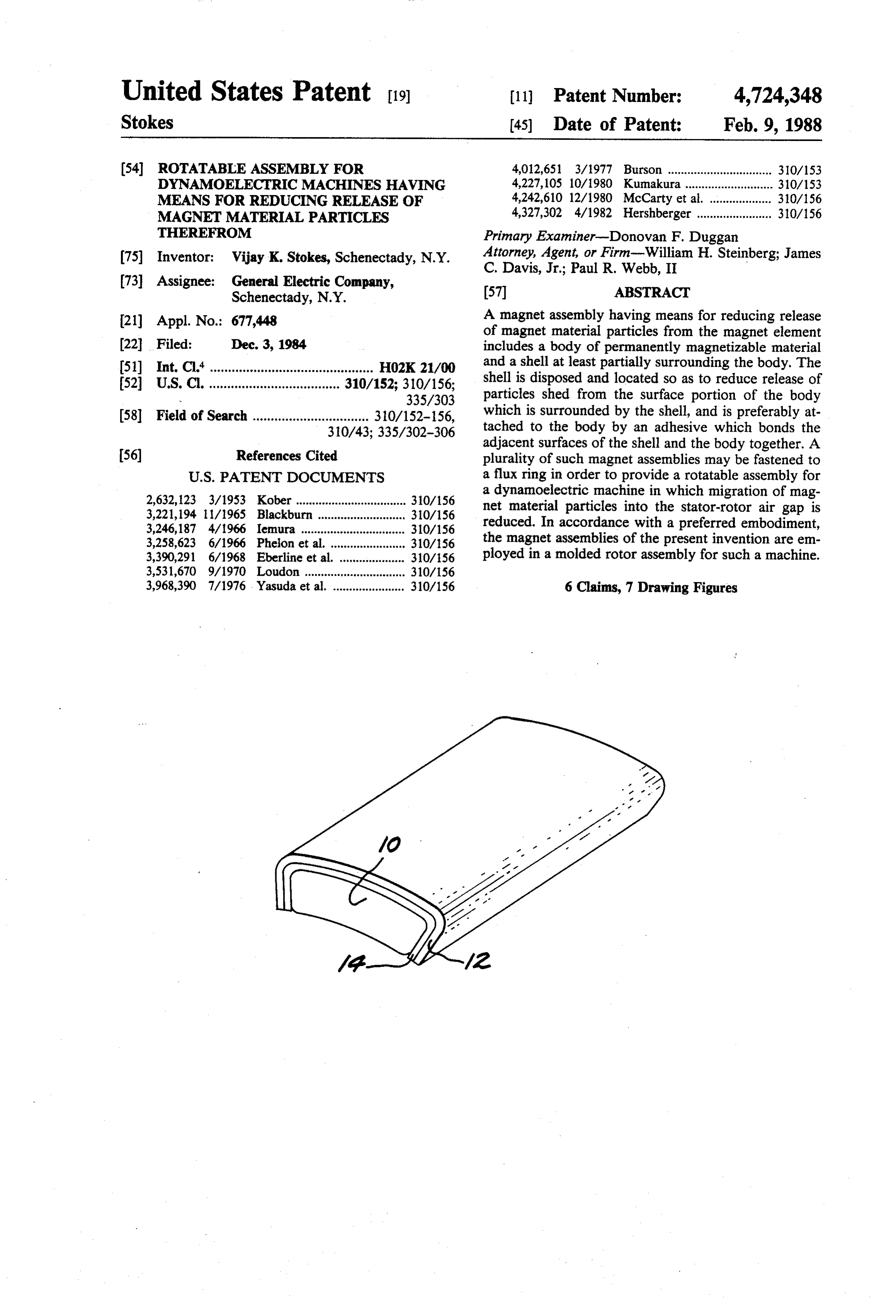
United States Patent (19) 11 Patent Number: 4,724,348 Stokes 45) Date of Patent: Feb. 9, 1988 (54) ROTATABLE ASSEMBLY FOR 4,012,651 3/1977 Burson ................................ 310/153 DYNAMOELECTRIC MACHINES HAVING 4,227,105 10/1980 Kumakura .... ... 310/153 MEANS FOR REDUCING RELEASE OF 4,242,610 12/1980 McCarty et al. ... 310/156 MAGNET MATERAL PARTICLES 4,327,302 4/1982 Hershberger ....................... 310/156 THEREFROM Primary Examiner-Donovan F. Duggan (75) Inventor: Vijay K. Stokes, Schenectady, N.Y. Attorney, Agent, or Firm-William H. Steinberg; James C. Davis, Jr.; Paul R. Webb, II (73) Assignee: General Electric Company, (57) ABSTRACT Schenectady, N.Y.
21 Appl. No.: 677,448 A magnet assembly having means for reducing release of magnet material particles from the magnet element 22 Filed: Dec. 3, 1984 includes a body of permanently magnetizable material (51) Int. Cl." ............................................. H02K 21/00 and a shell at least partially surrounding the body. The (52) U.S. Cl. .................................... 310/152; 310/156; shell is disposed and located so as to reduce release of 335/303 particles shed from the surface portion of the body (58) Field of Search ................................ 310/152-156, which is surrounded by the shell, and is preferably at 310/43; 335/302-306 tached to the body by an adhesive which bonds the adjacent surfaces of the shell and the body together. A 56) References Cited plurality of such magnet assemblies may be fastened to
2,632,123 3/1953 Kober .................................. 310/156 a dynamoelectric machine in which migration of mag 3,221,194 1/1965 Blackburn ... 30/156 net material particles into the stator-rotor air gap is 3,246,187 4/1966 Iemura ......... ... 310/156 reduced. In accordance with a preferred embodiment, 3,258,623 6/1966 Phelion et al. .... ... 310/156 the magnet assemblies of the present invention are em 3,390,291 6/1968 Eberline et al. . ... 310/56 ployed in a molded rotor assembly for such a machine. 3,531,670 9/1970 Loudon ............ ... 310/156 3,968,390 7/1976. Yasuda et al. ...................... 310/156 6 Claims, 7 Drawing Figures
Page 2
Drawing sheet — no readable text.
Page 3
Drawing sheet — no readable text.
Page 4
ROTATABLE ASSEMBLY FOR
ments tend to move radially at a different expansion rate than that of the metallic band, due to the low elastic
DYNAMOELECTRIC MACHINES HAVING modulus of the adhesive. Additionally, if the rotor core MEANS FOR REDUCING RELEASE OF MAGNET is made of plastic, the rotor core also tends to radially MATERAL PARTICLES THEREFROM expand at a different rate than the metallic band, be cause of the core's lower elastic modulus. To withstand
BACKGROUND OF THE INVENTION the stresses imposed by these mechanisms, the metallic This invention relates to rotatable assemblies for dy bands disclosed by U.S. Pat. Nos. 4,242,610 and namoelectric machines, such as electronically commu 10 3,531,670 appear to require relatively high mechanical tated motors. More particularly, it relates to a means for strength. U.S. Pat. No. 3,221,194, issued Nov. 30, 1965 reducing shedding of particles from the permanently to A. B. Blackburn, also appears to disclose a scheme magnetizable materials which are typically employed to which would tend to reduce migration of magnet mate form the magnet elements for such machines. rial particles into the stator-rotor gap. That patent de In conventional designs of rotatable assemblies for scribes dipping a rotor core with permanent magnet dynamoelectric machines, such as, for example, elec material elements arranged thereon into a plastic bath.
tronically commutated motors, permanent magnet ele When cured, the plastic forms an encapsulating layer ments are fastened to the outer surface of a steel drum which is attached to a rotatable shaft. In such designs, over curing both the rotor core and the magnet elements, se them together. However, for similar reasons as the permanent magnet elements form the outer surface discussed of the rotor assembly. The permanent magnet elements subjected toabove,
typically used in electronically commutated motor ro radial expansion of the stresses both hoop rotor and stresses imposed by assembly during rotation.
tors are formed from permanently magnetizable mate rial which has been made by powder metallurgical tech to Accordingly, it is an object of the present invention provide a magnet assembly having means for reduc niques. These materials are brittle and have a tendency to release microscopic particles or chips from their 25 ing release of magnet material particles from the surface of the magnet element.
surfaces, especially during rotation of the rotor assem It is a further object of the present invention to pro bly. Some of these released particles may migrate vide a rotatable magnet assembly in which the stresses through the stator-rotor air gap and settle on the inner surface of the stator, thereby affecting the stator-rotor imposed on the means employed for reducing release of gap and degrading motor performance. 30 magnet material particles from the magnet elements, Various schemes have been employed to retain mag tion, caused by radial expansion of the assembly during rota net material elements, such as permanent magnets or the are reduced.
like, against displacement from their proper positions in It is another object of the present invention to pro a rotatable assembly for dynamoelectric machines. It vide a rotatable assembly for dynamoelectric machines would appear that some of these schemes would also 35 in which migration of magnet material particles into the serve, at least in part, to reduce migration of magnet stator-rotor gap is reduced.
material particles into the stator-rotor gap. One such SUMMARY OF THE INVENTION scheme is disclosed in U.S. Pat. Nos. 4,242,610, issued
Dec. 30, 1980 to F. B. McCarty et al., and 3,531,670, In accordance with one aspect of the present inven issued Sept. 29, 1970 to D. C. Loudon. Those patents tion, a magnet assembly having means for reducing appear to describe heat shrinking a metal or metal alloy release of magnet material particles therefrom com sleeve or band about the rotor core into displacement prises a body of permanently magnetizable material and preventing engagement with a set of magnet material a shell at least partially surrounding the body. The shell elements arranged or otherwise seated in assembly posi is disposed and located so as to reduce release of parti tions about the circumference of the rotor core. While 45 cles shed from the surface portion of the body which is such an arrangement appears to at least partially reduce surrounded by the shell, and is preferably attached to migration of magnet material particles from the outer the body by an adhesive which bonds the adjacent sur surfaces of the magnet elements, this prior art arrange faces of the shell and the body together. ment requires undesirable heating during assembly, is In accordance with another aspect of the present too bulky and cumbersome for some applications, and is 50 invention, a plurality of such magnet assemblies are relatively expensive. To provide the metallic bands fastened to a flux ring in order to provide a rotatable disclosed in those patents with adequate strength to assembly for a dynamoelectric machine. The magnet hold the magnet elements in position, a relatively thick assemblies are disposed about the outer circumference material must be used. Furthermore, even if the magnet of the flux ring so that they are situated adjacent to each elements are fastened to the rotor core by a supplemen 55 other and so that the outer surfaces of the magnet as tary means such as adhesive bonding, it is still difficult semblies form the curved surface of a cylinder. The to provide such bands with adequate strength using a rotatable assembly may also include an axial shaft ex thin material. In addition to the hoop stresses in the tending along the central axis of the flux ring, and a metallic band generated during rotation of the rotor matrix molded between the shaft and the inner circum assembly by centrifugal forces acting on the band's own ference of the flux ring.
mass, radial expansion of the rotor assembly during rotation also imposes stresses on the band. The amount BRIEF DESCRIPTION OF THE DRAWINGS of radial expansion of the rotor assembly is expected to The subject matter which is regarded as the invention be greater than that of the metallic band for several is particularly pointed out and distinctly claimed in the reasons. First, during rotation the flux ring exhibits an 65 concluding portion of the specification. The invention incremental expansion due to centrifugal loading by the itself, however, both as to its organization and its attached magnet elements. Also, if the magnet elements method of practice, together with further objects and are adhesively bonded to the flux ring, the magnet ele advantages thereof, may best be understood by refer
Page 5
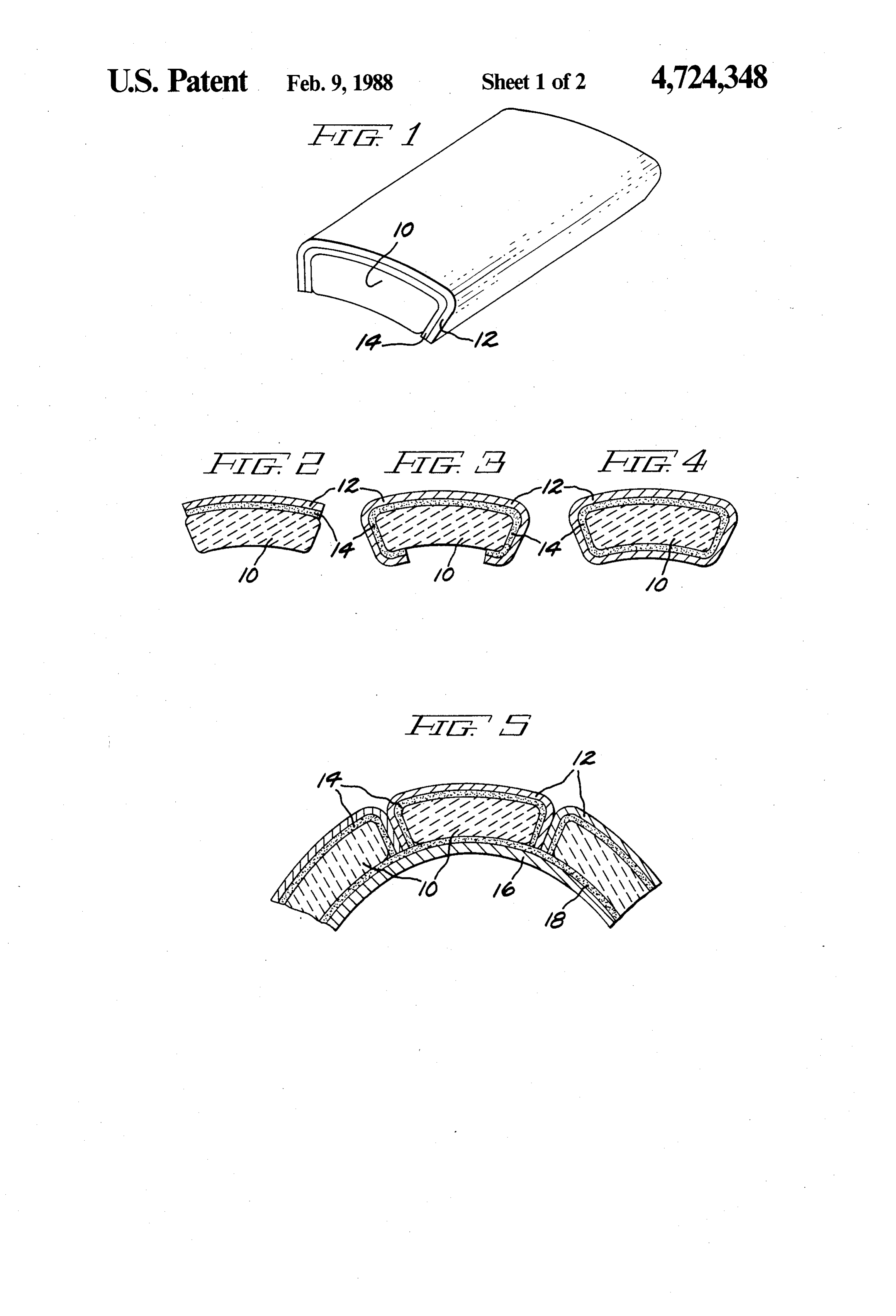
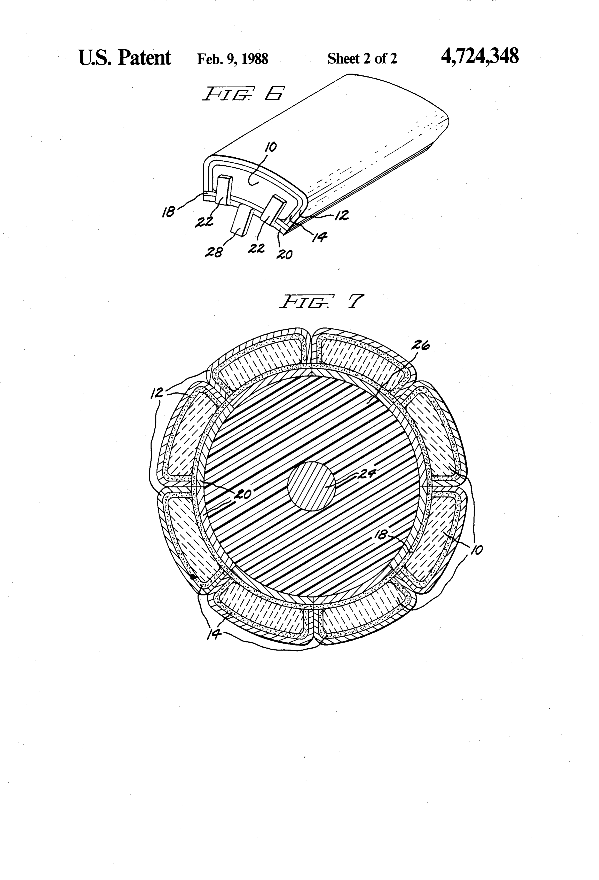
ence to the following description taken in conjunction FIG. 4. However, for some applications, the embodi with the accompanying drawings, in which: ment of FIG. 4 may be preferred over that of FIG. 3, FIG. 1 is a perspective view schematically illustrat since the embodiment of FIG. 4 results in a more uni ing one embodiment of a magnet assembly in accor form magnetic flux pattern. As between the magnet dance with the present invention; 5 assemblies of FIGS. 1 and 2, the embodiment shown in FIGS. 2-4 are cross-sectional end views schemati FIG. 1 provides a smoother overall outer surface for cally illustrating alternative embodiments to the em the magnet assembly, and is preferred for applications bodiment shown in FIG. 1; such as rotors for dynamoelectric machines. FIG. 5 is a cross-sectional end view schematically In each of the embodiments illustrated in FIGS. 1-4, illustrating a portion of one embodiment of a rotatable 10 body 10 of permanently magnetizable material has been assembly for a dynamoelectric machine in accordance shown as a generally bar-shaped body having generally with the present invention; arcuately shaped top and bottom surfaces. Although the FIG. 6 is a perspective view schematically illustrat principles of this invention apply to virtually any body ing a portion of another embodiment of a rotatable shape, the bar-shaped bodies shown are especially use assembly for a dynamoelectric machine in accordance 15 ful for such applications as electronically commutated with this invention; and motors. FIG. 5 schematically illustrates a portion of one FIG. 7 is a cross-sectional end view schematically embodiment of a rotatable assembly for such a dynamo illustrating a molded rotor assembly in accordance with electric machine, in accordance with the present inven the present invention. tion. The rotatable assembly comprises flux ring 16, for 20 providing a medium of distribution for magnetic flux,
DETAILED DESCRIPTION OF THE
PREFERRED EMBODIMENTS and a plurality of magnet assemblies disposed about the outer circumference of flux ring 16. In the embodiment
FIG. 1 schematically illustrates one embodiment of a shown in FIG. 5, the magnet assemblies are fastened to magnet assembly having means for reducing release of flux ring 16 by adhesive material 18. Each magnet as magnet material particles therefrom, in accordance 25 sembly is of the type shown in FIG. 1, and includes with the present invention. A body of permanently generally bar-shaped body 10 of permanently magnetiz magnetizable material 10 is at least partially surrounded able material, shell 12 at least partially surrounding by shell 12, with shell 12 being disposed and located so body 10, and attaching means 14 for attaching shell 12 as to reduce release of particles shed from the surface of to body 10. For each magnet assembly, shell 12 is dis body 10 which is surrounded by shell 12. Attaching 30 posed and located so as to reduce release of particles means 14 serves to attach shell 12 to body 10. As shown shed from the surface of body 10 which is surrounded in the cross-sectional views of FIGS. 2-4, attaching by shell 12. The magnet assemblies are fastened to flux means 14 preferably comprises an adhesive which ring 16 so that they are situated adjacent to each other bonds the adjacent surfaces of body 10 and shell 12 and so that the outer surfaces of the magnet assemblies together. Cladding the surface of body 10 by means of 35 form the curved surface of a cylinder. With the outer shell 12 and adhesive attaching means 14, in the manner surface and both side surfaces of each body 10 of perma illustrated in FIG. 1, results in containment of micro nently magnetizable material being surrounded by shell scopic particles and chips that would otherwise be re 12, and with the inner surface of each body 10 being leased from the surface of body 10. In order to minimize attached to flux ring 16, in the manner shown in FIG. 5, the effect of shell 12 on the magnetic performance of 40 the amount of magnet material particles released from body 10, shell 12 preferably comprises a thin sheath of the magnet material elements during rotation of the material which does not significantly affect the mag assembly is significantly reduced. Hence, the rotatable netic properties of body 10. In one embodiment, shell 12 assembly of the present invention may be employed to comprises stainless steel foil. advantage in a dynamoelectric machine in order to In the embodiment shown in FIG. 1, shell 12 is lo 45 reduce migration of magnet material particles into and cated adjacent to the top surface and to both side sur through the stator-rotor air gap. At the same time, the faces of body 10, so as to reduce release of particles shed means employed for reducing release of magnet mate from those three surfaces of body 10. FIGS. 2-4 are rial particles does not require the use of materials hav cross-sectional end views schematically illustrating al ing relatively high mechanical strength. In the rotatable ternative embodiments to that shown in FIG. 1. In the 50 assembly of the present invention, shell 12 is not sub embodiment of FIG. 2, shell 12 is located adjacent to jected to stresses imposed by radial expansion of the only the top surface of body 10, so as to reduce release assembly during rotation. Furthermore, since shell 12 of particles shed from that surface. In the embodiments may comprise a relatively thin material, the hoop of FIGS. 3 and 4, shell 12 is located adjacent to the top stresses generated during rotation of the assembly by surface, both side surfaces, and at least a portion of the 55 centrifugal forces acting on the mass of shell 12 are bottom surface of body 10, so as to reduce release of relatively small. Accordingly, the means for reducing particles shed from the top surface, from both side sur release of magnet material particles employed by the faces, and from at least a portion of the bottom surface present invention may comprise lightweight, relatively of body 10. If the magnet assemblies illustrated in FIGS. low strength materials.
1-4 are to be mounted on a flux ring, with the bottom In the embodiment of FIG. 5, the magnet assemblies surface of body 10 attached to the outer surface of the are shown as being of the type illustrated in FIG. 1, flux ring, the embodiments shown in FIGS. 3 and 4 with shell 12 of each magnet assembly being located would likely result in a loss of magnetic flux between adjacent to the outer surface and to both lateral surfaces body 10 of permanently magnetizable material and the of body 10 so as to reduce release of particles shed from flux ring. Because, in the embodiment shown in FIG. 3, 65 those surfaces. However, the magnet assemblies illus shell 12 only partially covers the bottom surface of trated in FIGS. 2-4 may also be used. As was noted body 10, the loss of magnetic flux would be smaller for above, shell 12 preferably comprises a material which that embodiment than for the embodiment shown in does not significantly affect the magnetic performance
Page 6
of body 10 of permanently magnetizable material, such shaped flux ring formed by either flux ring 16 shown in as, for example, stainless steel foil. Attaching means 14 FIG. 5 or flux ring segments 20 shown in FIGS. 6 and preferably comprises an adhesive which bonds the adja 7. Matrix 26 is molded between shaft 24 and the inner cent surfaces of shell 12 and body 10 together. circumference of the flux ring so that matrix 26 is at In one embodiment of the rotatable assembly of the least in part in supporting relationship between shaft 24 present invention, the flux ring employed comprises a and either flux ring 16 or flux ring segments 20. Each unitary annular structure, illustrated in FIG. 5 as flux body 10 of permanently magnetizable material is at least ring 16. FIG. 6 schematically illustrates a portion of an partially surrounded by shell 12, in the manner shown in alternative embodiment in which the flux ring com FIGS. 1-4. Regardless of which of the embodiments prises a plurality offlux ring segments 20, with each flux 10 shown in FIGS. 1-4 is used, shell 12 covers at least the ring segment 20 having mounted thereon one or more outer surface of the magnet assemblies shown in FIGS. 1-4. In the each body 10 of is each body 10, and the inner surface of attached to either flux ring 16 or flux specific embodiment shown in FIG. 6, the magnet as sembly of FIG. 1 is employed. As shown by the cross ring segments 20. Hence, magnet material particles are constrained from being released during rotation of the sectional end view of FIG. 7, which schematically illus 15 molded rotor assembly, and the migration of such parti trates a molded rotor assembly in accordance with the cles into the stator-rotor gap is reduced. present invention, in order to form a rotatable assembly, The foregoing describes a magnet assembly having flux ring segments 20 are circumferentially arranged in means for reducing release of magnet material particles a spaced-apart relationship about a central axis and held from the surface of the magnet element. The present in position by a supporting means so that flux ring seg 20 invention ments 20 form the general shape of an annulus. In the which thealso provides a rotatable magnet assembly in stresses caused by radial expansion of the embodiment of FIG. 7, the supporting means comprises assembly during rotation, and imposed on the means molded matrix 26. The rotatable assembly embodied by employed for reducing release
FIG.7 may be formed, for example, by fastening one or cles, are reduced. The presentofinvention magnet material parti further pro more magnet assemblies to each flux ring segment 20, vides a rotatable assembly for dynamoelectric
machines arranging the flux ring segments having the magnet assemblies fastened thereto in an appropriately shaped in which migration of magnet material particles into the mold, and then molding in a matrix material, such as, for stator-rotor gap is reduced.
While the invention has been described in detail example, phenolic.
The means for fastening the plurality of magnet as 30 herein in accord with certain preferred embodiments semblies to either flux ring 16, shown in FIG. 5, or flux thereof, many modifications and changes therein may ring segments 20, shown in FIGS. 6 and 7, may com be effected by those skilled in the art. For example, prise adhesive material 18 which bonds the magnet while body 10 of permanently magnetizable material assemblies to either flux ring 16 or to flux ring segments has been shown in the Figures as comprising a ceramic, 20, respectively. As illustrated in FIG. 6, the fastening 35 the principles of the present invention apply to other means may also comprise a plurality of locking tabs 22, materials for which particle shedding is a problem. which may be formed as an integral part of either flux Also, for the sake of clarity in illustrating the present ring 16 shown in FIG. 5 or flux ring segments 20 shown invention, shell 12 is not shown in any of the figures as in FIG. 6. Locking tabs 22 are disposed and located so covering the end surfaces of body 10. However, it that they are in gripping engagement with confronting should be understood that such surfaces could also be parts of the magnet assemblies, so as to at least in part covered by shell 12, and that such an embodiment is retain the magnet assemblies against displacement from included in the scope of the present invention. Further their respective positions. Also, while the means for more, although not shown in the Figures, the flux ring attaching matrix 26 to either flux ring 16 or flux ring to which the magnet assemblies of the present invention segments 20 may comprise adhesive bonding, the at 45 are mounted may comprise a steel drum in accordance taching means may also comprise protuberances which with the conventional design, in which a plurality of are formed on either flux ring 16 or flux ring segments stacked steel laminations are mounted on the outer sur 20 and which are embedded in matrix 26. As illustrated face of a steel shell. Accordingly, it is intended by the in FIG. 6, in one embodiment the protuberances com appended claims to cover all such modifications and prise anchoring tabs 28 which are formed as an integral 50 changes as fall within the true spirit and scope of the part of either flux ring 16 or flux ring segments 20. invention.
Anchoring tabs 28 extend radially inwardly beyond the The invention claimed is:
inner surface of either flux ring 16 or flux ring segments 1. A magnet assembly comprising: 20, for anchoring engagement in matrix 26. In the em a body of permanently magnetizable material includ bodiment shown in FIG. 6, locking tabs 22 and anchor 55 ing top and bottom surfaces; ing tabs 28 are located at the axial ends of flux ring a shell comprising a thin layer of nonmagnetic mate segments 20. However, other locations may be used, rial surrounding at least said top surface of only one such as, for example, along the lateral surfaces of seg body for reducing the release of particles there ments 20, or between the lateral surfaces of segments 20 from; and in locations intermediate the axial ends of the segments. means disposed between said body and said shell for In yet another embodiment of the present invention, attaching said shell to said body; the rotatable assembly described above is employed to said bottom surface of said body shaped for mounting form a molded rotor assembly for a dynamoelectric on a generally cylindrical ring surface; machine. As illustrated in FIG. 7, such a molded rotor said body shaped such that at least two of said magnet assembly includes one of the embodiments of a rotatable 65 assemblies can be mounted in adjoining relation assembly in accordance with the present invention, and ship on said ring surface so that said top surfaces further comprises axial shaft 24 and molded matrix 26. and said separate shells form a generally cylindrical Shaft 24 extends along the central axis of the annularly outer surface overlying said ring surface.
Page 7
2. The magnet assembly of claim 1 wherein said shell ally bar-shaped body further including two side comprises stainless steel. surfaces;
3. The magnet assembly of claim 1 wherein said a shell comprising a thin layer of nonmagnetic mate means for attaching said shell to said body comprises an rial surrounding said top surface said two side sur adhesive which bonds the adjacent surfaces of said shell 5 faces and at least a portion of said bottom surface of and said body together. said body for reducing the release of particles 4. The magnet assembly of claim 1 wherein said body therefrom; and of permanently magnetizable material comprises agen means disposed between said body and said shell for erally bar shaped body further including two side sur attaching said shell to said body; faces connecting said top and bottom surfaces. 10 said bottom surface of said body shaped for mounting 5. The magnet assembly of claim 4 wherein said shell on a generally cylindrical ring surface; surrounds said top surface and said two side surfaces of said body shaped such that at least two of said magnet said body. assemblies can be mounted in adjoining relation 6. A magnet assembly comprising: ship on said ring surface so that said top surfaces a body of permanently magnetizable material includ- 15 and said shells form a generally cylindrical outer ing top and bottom surfaces, said body of perma surface overlyingk said ringk surface. nently magnetizable material comprising a gener t k six
Provenance
- Collection
- Cited prior art
- Original PDF
- patentimages.storage.googleapis.com →
- Filed
- 1984-12-03
- Pages
- 7
- Method
- pdftotext (the PDF's own text layer) + pdftoppm 300dpi page scans
- Source
- Google Patents bibliographic record
- Granted
- 1988-02-09
- Inventors
- Vijay K. Stokes; General Electric Co
- Transcribed from
- patentimages.storage.googleapis.com →