patent · US4702693
Gas-fired infrared heater
27 October 1987
Page 1 — bibliographic record
United States Patent (19) 11 Patent Number: 4,702,693 Fraioli 45) Date of Patent: Oct. 27, 1987 (54) GAS-FIRED INFRARED HEATER body of a material radiating infrared energy when 76 Inventor: Joseph Fraioli, 8 Seymour Pl, White heated to an elevated temperature by the burner. The Plains, N.Y. 10605 burner is formed by a metal pipe having a longitudinal ly-extending outlet defined by a pair of parallel plates 21 Appl. No.: 937,220 projecting laterally from the pipe and having a set of 22 Filed: Dec. 3, 1986 corrugated ribbons therein, a pad of thermal insulation being secured to the outer surface of each plate, 51) Int. Cl." .............................................. F23D 14/12 whereby when a mixture of air and gas is fed into the 52 U.S.C. .................................. 431/348; 126/92 R pipe and ignited, a sheet of flame emerges from the 58) Field of Search ............. 431/347, 348; 126/92 R, outlet. The burner is received within a longitudinally
extending internal channel in the refractory body, the (56) References Cited outlet being then aligned with an internal cavity so that
3,366,156 1/1968 Belknap ............................... 431/348 face of the cavity to heat this surface to an elevated 3,881,858 5/1975 Fitzgerald .... ... 43/348 temperature causing it to emit infrared radiation. The 4,507,083 3/1985 Fraioli................................. 432/222 cavity communicates with an array of openings in the body which form radiation horns to produce the desired
Primary Examiner-Carroll B. Dority, Jr. directional infrared radiation pattern. Because the Attorney, Agent, or Firm-Michael Ebert burner is thermally shielded in the channel, metal fa 57 ABSTRACT tigue and deleterious distortion of the ribbons is avoided A gas-fired infrared heater for projecting an infrared even at very high operating temperatures. beam in a directional radiation pattern. The heater is constituted by a ribbon-type burner and a refractory 9 Claims, 7 Drawing Figures
Page 2
Drawing sheet — no readable text.
Page 3
Drawing sheet — no readable text.
Page 4
Drawing sheet — no readable text.
Page 5
Drawing sheet — no readable text.
Page 6
cost of the product to the consumer. Also, with convec
GAS-FIRED INFRARED HEATER tion ovens, the flow of hot air over the surface of the food product tends to deprive it of moisture and volatile
BACKGROUND OF INVENTION constituents and therefore degrades the quality of the 1. Field of Invention product.
This invention relates generally to infrared burners Radiation heaters in present commercial use are of constituted by a ribbon type gas fired burner and a the infrared type, the infrared band of thermal radiation refractory body which when heated by the burner lying within the electromagnetic wave spectrum. The projects an infrared beam in a directional radiation pat O quality and intensity of radiation in the infrared band of tern, and more particularly to a heater of this type in 0.7 microns to 400 microns depends on the temperature which the burner which is of metallic construction is of the radiating body. If, therefore, the radiating body is accommodated within the refractory body and is so a refractory ceramic heated by a gas-fired jet burner, shielded from heat as to avoid metal fatigue. one can only accurately adjust the quality and intensity 2. Status of Prior Art: of the IR radiation if it is possible to carefully control The transfer of heat takes place by three processes: 15 the operation of the gas-fired burner. conduction, convection and radiation. In conduction, Despite the fact that IR heaters are much more eco heat is transferred through a body by the short range nomical to operate and act with extreme rapidity, and interaction of molecules and/or electrons. Convection IR heaters are therefore far superior in this regard to involves the transfer of heat by the combined mecha 20 convection ovens for cooking or baking food, they have nisms of fluid mixing and conduction. In radiation, elec enjoyed limited success in the baking industry. The tromagnetic energy is emitted toward a body and the reason for this is that commercially available gas-fired energy incident thereto is absorbed by the body to raise IR heaters are relatively difficult to control and also its temperature. Radiant heating, therefore, differs from give rise to an uneven baking action. both convection and conduction heating, for the pres Effective infrared heating depends not only on the ence of matter is not required for the transmission of 25 radiant source temperature but also on what is referred radiant energy.
According to the Stefan-Boltzmann law, the rate of to as the "geometric view factor.' This factor deter mines the relationship between the pattern of IR radia heat transfer between a source of radiated heat whose tion and the surface of the product being heated. With temperature is Tsand an absorbing body whose temper the typical ature is This equal to T-Th; that is, to the difference product to beIRheated 30 heating arrangement, portions of the are more completely exposed to between the fourth powers of these temperature values. IR rays and will be heated more rapidly to a high tem In convection heating, the rate of heat transfer is pro perature than those portions that are not as fully ex portional only to the temperature difference between posed. As a consequence, the product may not be prop the body being heated and the surrounding atmosphere. erly baked and may not be commercially saleable. Hence convection heating is inherently very slow, as 35 The drawback of IR heating with existing equipment compared to the nearly instantaneous effects of radiant heating. is recognized in the article "Radiant Convection Hea Though an IR heater in accordance with the inven ting-A Marriage of Two Systems' by H.J. Bennett, tion may be used throughout the full range of heating which appeared in the journal Industrial Gas for Febru applications, including industrial processes such as in ary 1976. In order to overcome the uneven heating dustrial finishing and textile treatment, as well as in experienced with IR heating, the author proposes com annealing, curing and drying operations which require bining an IR heater with a convection heater so as to heating, it will mainly be described herein in connection provide a heating technique somewhat faster than con with the heating of food products; for the invention has vection heating, yet with the uniformity and controlled particular advantages in that context. 45 temperature characteristics of convection heating. While a food product typically undergoes cooking or The fact is, however, that the synthesis of IR and baking at a temperature in the range of about 140 to convection heating represents a compromise that is not 200 F. whose upper value is below the boiling point of entirely satisfactory, for it requires much more energy water (212 F.), it is nevertheless necessary in a conven than IR heating and also a confined oven as well as tional convection oven to establish a much higher oven SO separate controls for the heater and the oven. temperature-usually well over 400' F. The reason for Ideally, with a food product, such as dough to be this requirement is that the transfer of heat between the baked, having an exposed surface of given dimensions, hot atmosphere of the convection oven and the body of the geometry of the IR beam impinging on this surface food takes place at a fairly rapid rate only when the should be such as to impinge on all points thereon IR temperature differential therebetween is great. 55 rays of equal intensity so that the baking is uniform If, therefore, the food placed in an oven is initially at throughout the body of the food. But existing IR heat room temperature and the oven temperature is held at ers are incapable of producing an IR radiation pattern of about 200 F., then as the body of the food becomes uniform flux density which is so shaped as to uniformly warmer and its surface temperature rises to, say, 150 irradiate and heat a given food product. F., the rate of heat transfer as the temperature differen 60 It is known to provide infrared heaters in which a tial narrows thereafter becomes increasingly slow, and refractory body is heated by means of a ribbon-type the cooking or baking process is protracted. On the burner to an elevated temperature causing it to emit other hand, if the oven temperature is raised to 400 F. infrared radiation.
or 500F. to speed up baking, this means that the entire The ribbon-type burner is of the type disclosed, for volume of air in the oven must be at this elevated tem 65 example, in the Flynn U.S. Pat. No. 3,437,322, the gas perature, and this entails a relatively large energy ex air fuel mixture is fed into a cylinder having a longitudi penditure. With rising energy costs, this factor adds nal slot therein occupied by a stack of corrugated rib substantially to the cost of baking and is reflected in the bon to create an array of minute jet openings through
Page 7
which the gas-air mixture is expelled. Because of the myriad of jet openings, the projected flame is not com 1,486,036 3/1924 Rinsinger posed of discrete jets but assumes a sheet-like form. 1,529,871 3/1925 Conroy et al. However, the intensity of the flame is not uniform 2,200,169 5/1940 Hammick throughout the length of the ribbon, for the pressure of 5 2,731,010
Moore et al.
Milligan the gas-air mixture in the cylinder is not equalized 3,437,322 4/1969 Hynn throughout its length. Hence, the resultant infrared 3,954,388 5/1976 Hildebrand radiation pattern is not of uniform intensity; and when 4,432,727 2A1984 Fraioli food is subjected to this pattern, the heating thereof may be uneven.
In order to overcome this problem, my prior U.S. SUMMARY OF INVENTION Pat. No. 4,507,083 (1985) discloses a gas-fired infrared In view of the foregoing, the main object of this in heater for projecting an infrared beam in a radiation vention is to provide an infrared heater for projecting pattern having a predetermined geometry for irradiat an infrared beam in a directional radiation pattern ing the surface of a food product or other body to effect which makes use of a ribbon-type burner producing a uniform heating thereof at a rapid rate. The heater in sheet of flame, the burner being received in a refractory cludes a ribbon-type burner having an elongated pre body and being so shielded from heat emitted by the mix casing into which is fed air and gas, and an outlet body as to avoid metal fatigue and distortion of the extending along a slot in the casing and projecting ribbons.
therefrom. The outlet is provided with two sets of cor Also an object of the invention is to provide an infra rugated ribbons separated by a gas pressure chamber, red heater of the above type which is of the single whereby the air-gas mixture from the casing passes burner or double-burner type to create a simplex or through one set into the chamber where the pressure duplex unit.
thereof is equalized before the mixture passes through Yet another object of the invention is to provide the other set from which it emerges as a sheet of flame infrared heaters whose refractory body is constituted by of uniform intensity. The outlet is inserted in the longi replaceable modular blocks whereby the heater may be tudinal socket of a refractory body to impinge on a readily assembled and repaired. surface thereof whereby the surface is heated to a ten Briefly stated, these objects are attained in a gas-fired perature level causing the surface to emit infrared en infrared heater for projecting an infrared beam in a ergy which is projected by an array of radiation horns directional radiation pattern. The heater is constituted formed in the assembly. by a ribbon-type burner and a refractory body of a As pointed out in my above-identified patent, in an material radiating infrared energy when heated to an infrared heater which makes use of a gas-fired burner to elevated temperature by the burner. The burner is heat a refractory body to produce infrared radiation, formed by a metal pipe having a longitudinally-extend some of the infrared energy from the refractory body is ing outlet defined by a pair of parallel plates projecting directed back toward the ribbon type burner. With laterally from the pipe and having a set of corrugated prolonged operation, this infrared energy which is ab ribbons therein, a pad of thermal insulation being se sorbed by the metal of the heater results in metal fatigue cured to the outer surface of each plate, whereby when and may render the burner inoperative. a mixture of air and gas is fed into the pipe and ignited, In order to overcome this problem, my prior patent a sheet of flame emerges from the outlet. The burner is shapes the cavity in the refractory body so that the received within a longitudinally-extending internal surface thereof onto which the flame impinges is in channel in the refractory body, the outlet being then clined relative to the outlet of the ribbon burner at an aligned with an internal cavity so that the flame emerg angle at which no infrared energy from this surface is ing from the outlet impinges on a surface of the cavity directed toward said outlet. to heat this surface to an elevated temperature causing it However, while this is an adequate solution to this to emit infrared radiation. The cavity communicates problem for operating temperatures running as high as with an array of openings in the body which form radia 800 F., when the operating temperatures are very high tion horns to produce the desired directional infrared -that is, above 1200 F-then with prolonged opera radiation pattern. Because the burner is thermally tion, the ribbon burner is subjected to temperatures shielded in the channel, metal fatigue and deleterious which not only result in metal fatigue but also in the distortion of the ribbons is avoided even at very high deformation of the stainless steel ribbons which define operating temperatures.
the array of minute jet openings through which the OUTLINE OF DRAWINGS gas-air mixture is expelled. These myriad openings nor For a better understanding of the invention as well as mally have a substantially uniform diameter and resultother objects and further features thereof, reference is in a projected flame whose intensity is uniform through made to the following detailed description to be read in out the length of the ribbon, assuming that the pressure conjunction with the accompanying drawings, wherein:
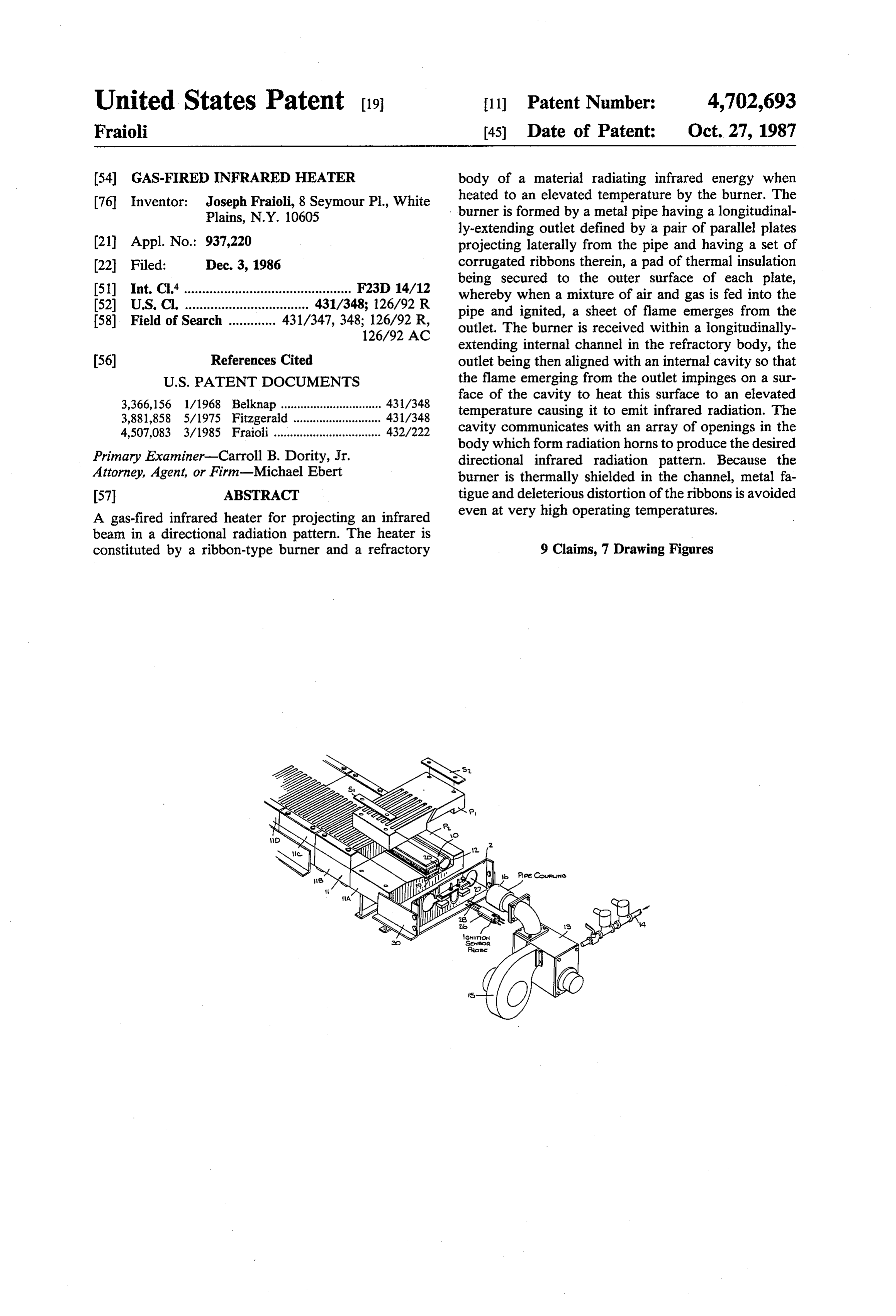
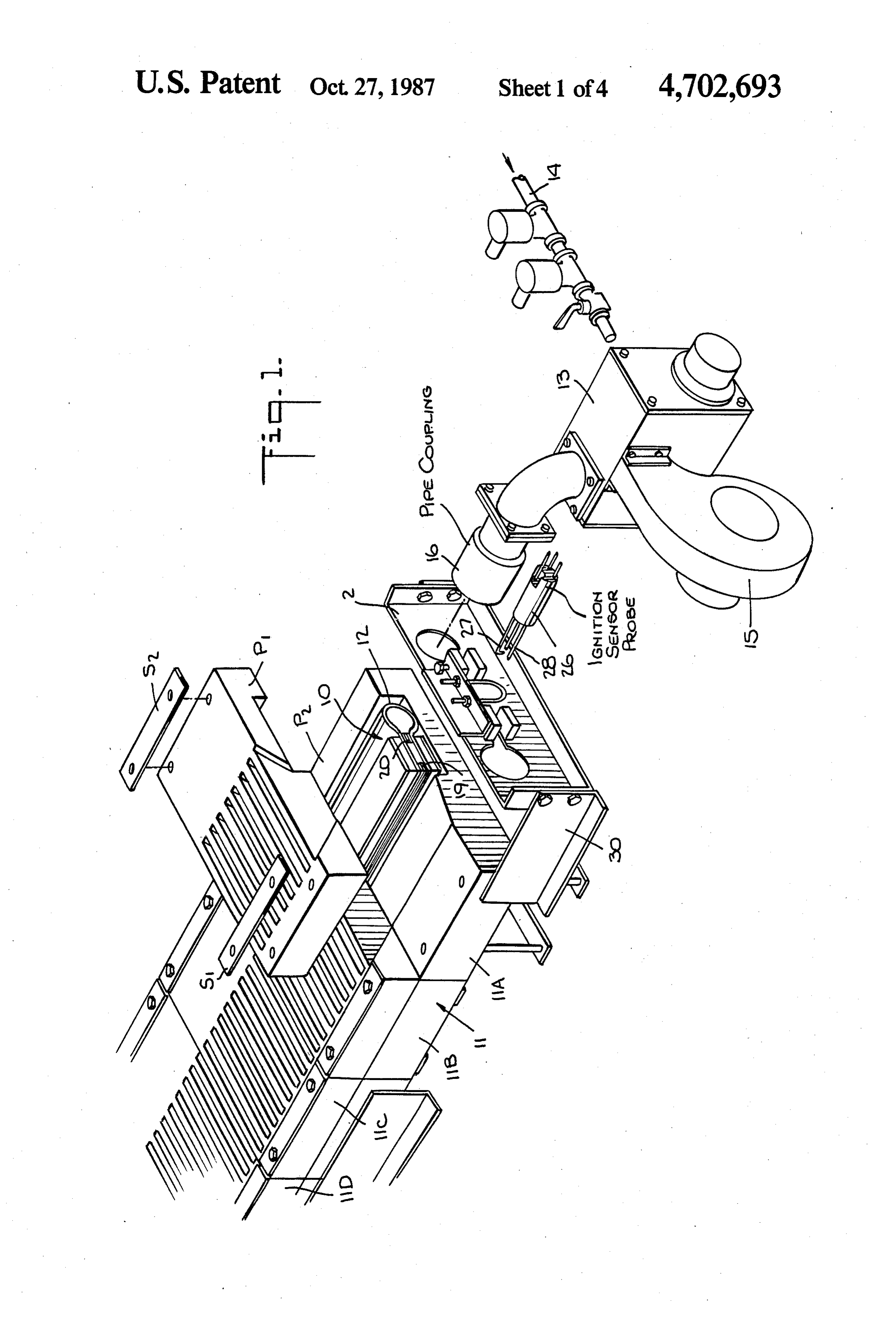
of the gas-air mixture is equalized throughout this 60 FIG. 1 is a perspective view of a simplex infrared length. heater in accordance with the invention, one of the But if the metal ribbons become distorted because of modular block pieces of the refractory body being heat fed back to the burner outlet by the refractory raised to expose the ribbon-type burner; body, then the jet openings will no longer be of uniform FIG. 2 is an end view of a simplex modular block diameter, and the resultant flane will be of uneven 65 included in the simplex heater;
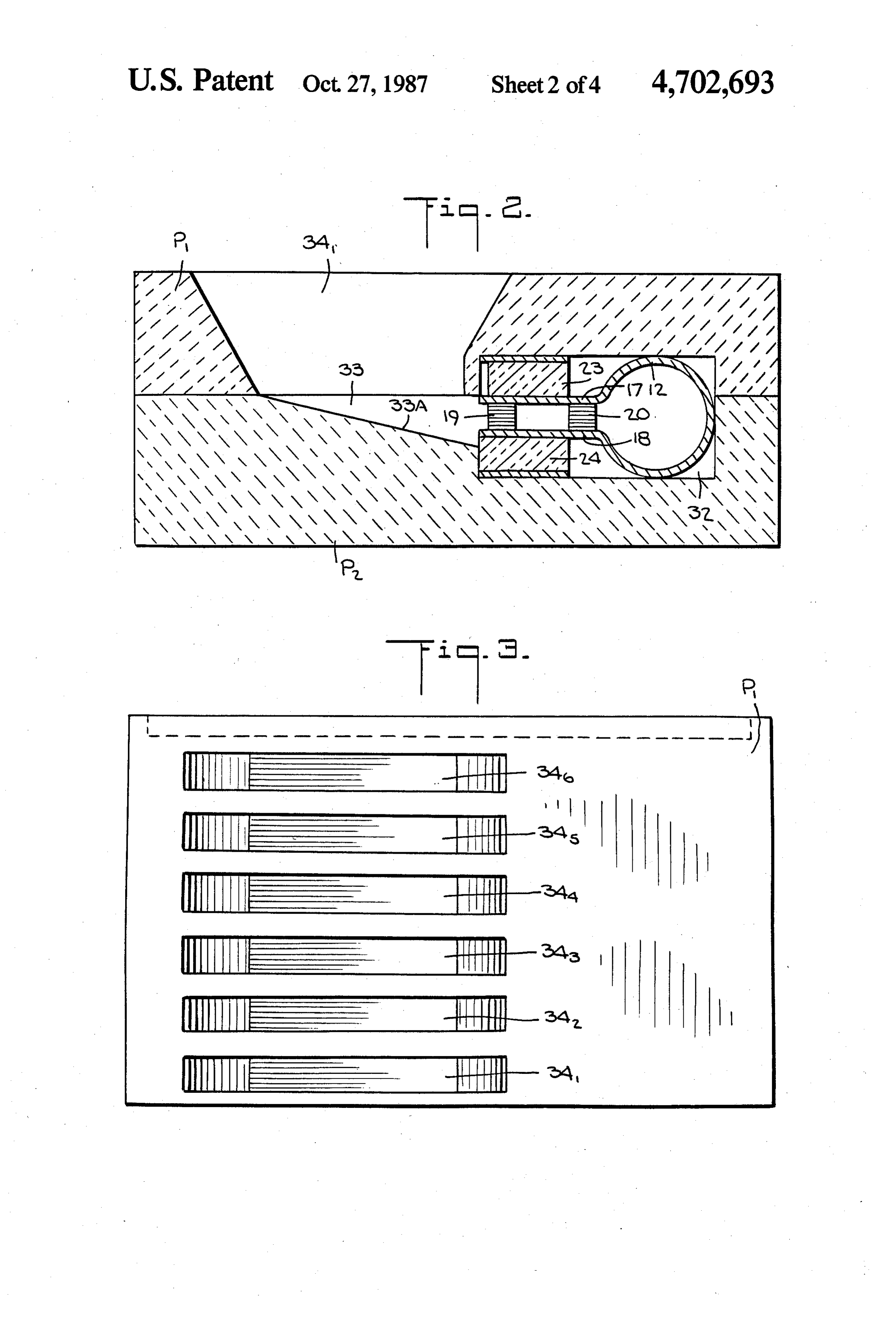
density. Hence the burner will not operate properly. FIG. 3 is a top view of the modular block; Of background interest in regard to infrared burners FIG. 4 is a perspective view of the ribbon-type are the following patents: burner included in the simplex heater;
Page 8
FIG. 5 is a side view of the burner; equalize the pressure in chamber 21. Thus, while the FIG. 6 is a perspective view of a duplex infrared pressure throughout the pre-mix chamber tends to vary heater in accordance with the invention; and at various regions therein, the pressure of the mixture FIG. 7 is a perspective view of the ribbon type burner when it is ejected into the atmosphere from the first set included in the duplex heater. 5 of ribbons is equalized, and the resultant sheet of flame
DESCRIPTION OF INVENTION
has an equalized intensity giving rise to an infrared beam of uniform intensity.
The Simplex Unit: In order to prevent distortion of the ribbons in the Referring now to FIG. 1, there is shown a simplex two sets thereof in the outlet as a result of excessive infrared heater according to the invention constituted 10 heat, clamped onto the upper plate 17 of the outlet by a by a ribbon-type gas-air burner, generally designated by clamping strip 22 is a pad 23 of thermal insulation mate numeral 10, which cooperates with a refractory body, rial. In practice, pad 23 may be of the same material as generally designated by numeral 11. that of the refractory body. The lower plate 18 of the The burner includes a pre-mix pipe 12 of a suitable outlet has a like thermal insulation pad 24 clamped metal such as cast iron or stainless steel. Pipe 12 is sup 15 thereto by a strip 25.
plied with a mixture of air and gas through a dual valve As shown in FIG. 1, ignition of the air-gas mixture in air-gas controller 13, preferably of the type disclosed in the outlet of the burner is effected by a probe 26 pro my copending application Ser. No. 780,666, filed Sept. vided with an ignition spark gap 27 and a heat sensor 26, 1985 and now U.S. Pat. No. 4,640,678. This control element 28. This sensor makes it possible to effect auto ler is supplied with pressurized gas through an inlet line 20 matic control of the burner in the manner disclosed in 14 and pressurized air through an air blower 15. the above-identified copending application, whose en Controller 13 is adapted to mix the incoming air and tire disclosure is incorporated herein by reference. gas to produce a combustible output mixture and to The refractory body 11 is composed of a bank of four adjust the flow rate thereof without, however, altering identical modular blocks 11A, 111B, 11C and 11D. the air/gas ratio. The output of controller 13 is supplied 25 Each block is formed by complementary upper and by a coupler 16 to the inlet of burner pipe 12 whose lower pieces P1 and P2 which are clamped together by other end is closed. The preferred air/gas ratio is the clamping strips S1 and S2 and bolts. The four blocks are stoichiometric ratio that results in complete combustion supported in side-by-side relation within a frame consti in the burner. Thus, in the case of methane gas, this ratio tuted by front and rear end plates 29 and side plates 30 is 64 grams of oxygen to 16 grams of methane. How 30 which are bolted together. In practice, a greater or less ever, every chemical reaction has its characteristic pro number of blocks may be used to form a refractory portions; hence the ratio for optimum efficiency will body, depending on the length of the burner pipe. depend on the gaseous fuel being used. Each block is composed of refractory material, a Since the optimum ratio, once it is set, is never varied preferred material for this purpose being "Cera Form,' by controller 13, this ratio is maintained as the flow rate 35 a refractory produced by Johns-Manville of Denver, is adjusted. Hence one may accurately vary the inten Colo., made from a wet slurry formulation that includes sity of heat produced by the burner and the resultant refractory fibers and multi-component binder systems. temperature of the refractory body. Thus “Cera Form” type 103 includes Alumina (39.6%) As best seen in FIGS. 4 and 5, the pre-mix pipe 12 of and Silica (50.7%). Because the material can be molded, the burner is provided with a longitudinally-extending 40 it can be made into the special shapes called for in the slot which is defined by a pair of parallel metal plates 17 present application. In practice, however, the refrac and 18 integral with pipe 12 and extending laterally tory body may be molded in integral form rather than therefrom to form the outlet of the burner. The front being made up of individual blocks or modules. While a end of the outlet is occupied by a stack of corrugated fibrous refractory body has been disclosed, the infrared ribbons forming a first set 19. The corrugated ribbon 45 emitting material may be of ceramic or any other suit stack creates an array of minute jet openings through able composition.
which the gas-air mixture is forced. The configuration The pieces P1 and P2 of each block, as shown in of the ribbons is such as to provide two distinct type of FIGS. 2 and 3, are molded or otherwise formed so as to jet ports, one being a main flame jet port which is of the create, when the pieces are joined together, an internal high velocity type causing the gas-air mixture to project 50 channel 32 therein having a rectangular cross section with sufficient energy to form a long flame, the others whose dimensions are such as to snugly accommodate on either side of the main flame jet port being pilot jet the ribbon burner 10. Channel 32 which receives the ports of the low velocity type to produce relatively burner communicates with an interior cavity 33 formed short flames for sustaining the long main flame. Because in lower piece P2.
of the longitudinally-extending outlet arrangement and 55 Burner 10 is so placed in the channel as to align its the myriad jet openings created by the ribbons, the outlet with cavity 33 in the refractory body so that the projected main flame is not composed of discrete jets, flame emitted therefrom impinges the wall surface 33A but assumes a sheet-like form. to produce a high density flux of maximum radiance. At the inner end of the burner outlet is a parallel set The flame is not the source of infrared radiation, for its 20 of corrugated ribbons. These are separated from the 60 function is to heat the surface of the refractory to a first set by an air-gas pressure chamber 21. In operation, temperature level (i.e., 1800 to 2200 F) at which the the air and gas fed into pipe 12 are pre-mixed therein, refractory then emits infrared energy in the micron the mixture being forced through the second set of range to effect the desired heating of the product sub ribbons 20 to pass into the pressure chamber for more jected to the IR radiation pattern.
thorough secondary mixing therein. 65 As the temperature of the refractory surface is in Because the flow of the mixture through the outlet is creased, the maximum IR radiation occurs at shorter retarded between the two sets of ribbons, both of which wavelengths and has a much higher intensity, with an offer fluidic impedance, this retarding action serves to increasingly greater portion of the radiation occurring
Page 9
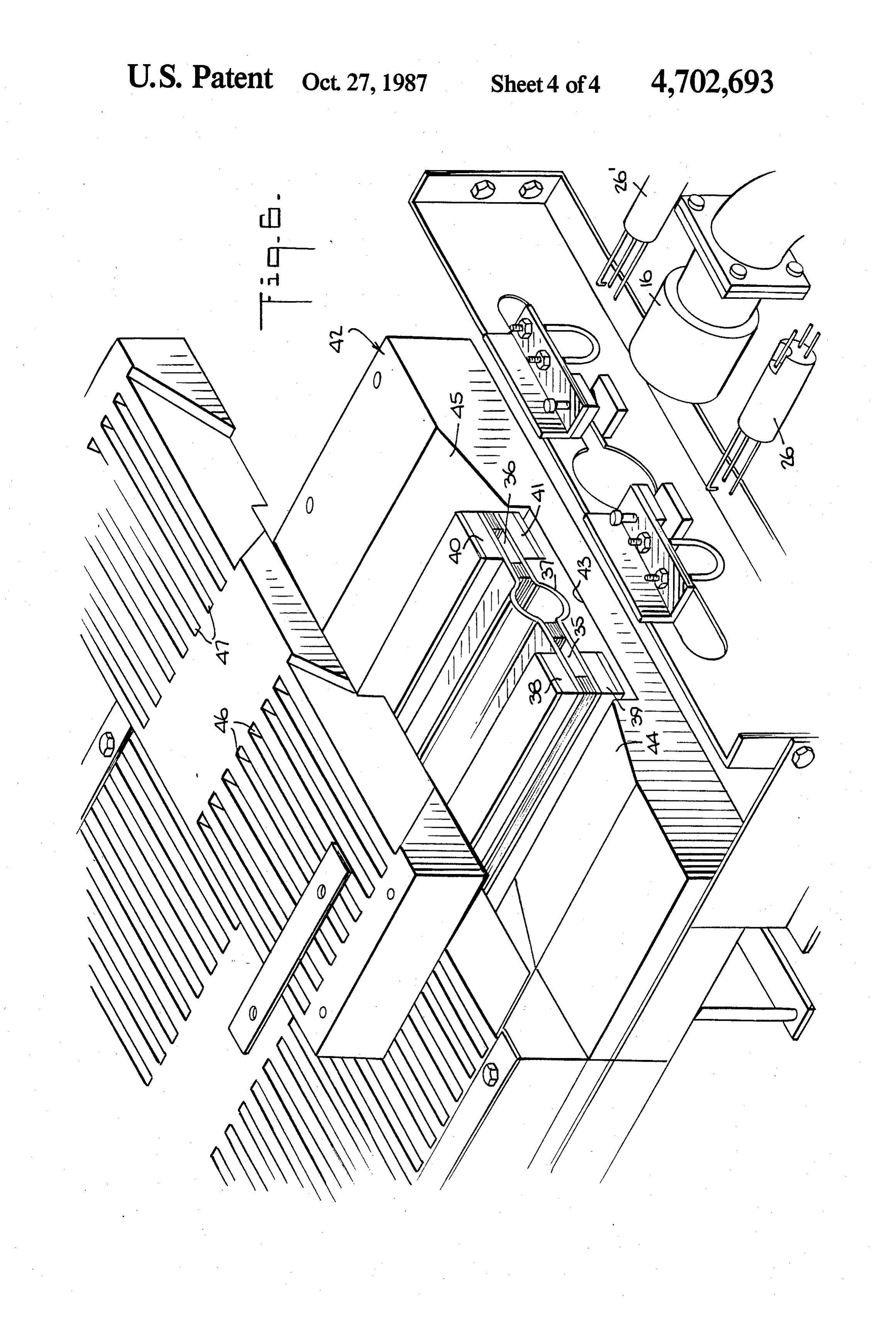
nearer the visible range in the electromagnetic spec is identical to that of a simplex or single burner unit trum. Infrared rays travel in a straight line until they except for the doubling thereof so that radiation beams strike an absorbing surface; hence radiant heat follows are projected from opposing sides of the unit, rather the same physical laws as light waves and travel at the than from one side only.
same speed. Though the burners have been shown as having a Formed in upper piece P is a parallel array of six cylindrical pre-mix pipe, in practice this pipe may have rectangular radiation horns 341 to 346 having side walls other cross-sectional forms such as square or rectangu which converge toward cavity 33. Hence the infrared lar.
radiation emitted from surface 33A of the cavity is While there has been shown and described a pre projected through the horns to provide a radiation pat O ferred embodiment of a gas-fired infrared heater in tern which depends on the geometry of the horns. accordance with the invention, it will be appreciated In operation, infrared radiation emitted by inclined that many changes and modifications may be made surface 33A of the refractory body is directed toward therein without, however, departing from the essential the radiating horns for projection toward the surface of spirit thereof.
an object to be heated. However, the angle of inclina 15 I claim:
tion of surface 33A is such that no radiant energy is 1. A gas-fired infrared heater comprising: directed toward the outlet of the ribbon burner; hence A. a ribbon-type burner constituted by a metal pipe the burner is protected from the consequences of radi supplied with an air-gas mixture, a pair of parallel ant heat. metal plates projecting laterally from alongitudinal As pointed out previously, when the infrared heater slot on the pipe to define an outlet, a set of ribbons is operating in a very high temperature range, the sandwiched between the plates at the front end of burner may then be subjected to back heat sufficiently the outlet to form myriad jet openings whereby a high to cause deformation of the ribbons thereon and sheet of flame emerges from the outlet when the metal fatique of the burner structure with deleterious mixture is ignited, and a pad of thermal insulation results. But because burner 10 is housed within internal 25 secured to the outer surface of each plate to protect cavity 32 in the refractory body it is thermally shielded said set of ribbons from excessive heating that from the infrared energy emitted in internal cavity 33 would result in a distortion of the ribbons; and projected through the radiation horns. Because of B. a refractory body of a material which when heated the sensitivity of the ribbons in the outlet to excessive to an elevated temperature level emits infrared heat, additional thermal shielding is provided by the 30 radiation, said body having an internal channel thermal insulation pads which protect the outlet plates therein which accommodates and thermally shields and isolate the ribbons from deleterious back heat that the burner, an internal cavity formed in the body in would otherwise distort the jet openings defined by the alignment with the outlet of the burner and having ribbons. a surface on which the flame impinges to cause this Because of the modular arrangement, assembly of the 35 surface to emit infrared radiation, and at least one unit can be carried out without difficulty; for it is a opening in the body communicating with the cav simple matter to first place the lower pieces P1 of the ity to define a horn from which said infrared radia blocks forming the refractory body in the frame, then tion is projected toward an object to be heated by place the ribbon burner 10 in the lower half of channel infrared energy.
32, after which the upper pieces P2 of the blocks are 2. A heater as set forth in claim 1, wherein said outlet placed over the ribbon burner and clamped to the lower includes a second set of ribbons adjacent the rear end of blocks to complete the unit. The unit may be readily the outlet to define between the two sets of ribbons a disassembled, when necessary, to replace any compo pressure chamber to equalize the pressure of the air gas nent thereof. mixture.
Duplex Unit: 45 3. A heater as set forth in claim 1, wherein said body Referring now to FIGS. 6 and 7 showing a duplex is formed by a bank of modular blocks in side-by-side infrared heating unit, it will be seen that this unit is a relation, each block being composed of complementary double-sided version of the single-sided simplex unit. upper and lower pieces which are shaped to define said Thus, in the duplex unit, the air-gas ribbon burner is channel, said cavity and said radiation horn. provided with outlets 35 and 36 on diametrically 50 4. A heater as set forth in claim 3, further including opposed sides of a central pre-mix pipe 37 which is means to clamp together said pieces.
supplied with an air-gas mixture by a coupler 16 as in 5. A heater as set forth in claim 4, further including a the simplex unit. And instead of a single ignition and frame to accommodate said blocks.
sensor probe 26, there is a like second probe 26, the 6. A heater as set forth in claim 1, wherein said sur probes cooperating with outlets 35 and 36, respectively. 55 face is inclined relative to the burner outlet at an angle Each outlet has two sets of ribbons and the outlet plates at which no infrared energy from this surface is directed thereof are thermally shielded by thermal insulation toward the outlet.
pads 38 to 41. 7. A heater as set forth in claim 1, wherein said pads In this embodiment of the invention, the refractory are clamped to said plates.
body is composed of modular twin blocks 42, each 60 8. A heater as set forth in claim 1, wherein said plates block having complementary upper and lower pieces are integral with said pipe and are made of stainless which when clamped together define an internal chan steel.
nel 43 for snugly accommodating the double-sided 9. A heater as set forth in claim 1, wherein said burner burner so that their twin outlets 35 and 36 are in align is provided with twin outlets at diametrically-opposed ment with opposing internal cavities in the refractory 65 sides of the pipe, and said refractory body is provided body having inclined surfaces 44 and 45. These cavities with twin cavities which are associated with the twin communicate with respective twin arrays of radiation outlets.
horns 46 and 47. Thus, the operation of this duplex unit k
Provenance
- Collection
- Cited prior art
- Original PDF
- patentimages.storage.googleapis.com →
- Filed
- 1986-12-03
- Pages
- 9
- Method
- pdftotext (the PDF's own text layer) + pdftoppm 300dpi page scans
- Source
- Google Patents bibliographic record
- Granted
- 1987-10-27
- Inventors
- Joseph Fraioli
- Transcribed from
- patentimages.storage.googleapis.com →