patent · US3751699
Gas filled vertical dynamoelectric machine
7 August 1973
Page 1 — bibliographic record
United States Patent (19) 11, 3,751,699 Gleichman (45) Aug. 7, 1973 54 GAS FILLED VERTICAL Primary Examiner-R. Skudy
DYNAMOELECTRIC MACHINE Attorney-Vale P. Myles et al.
(75. Inventor: Robert F. Gleichman, San Jose,
Calif. 57 ABSTRACT 73 Assignee: General Electric Company,
Schenectady, N.Y. A totally enclosed, inert gas filled vertical dynamoelec tric machine is described wherein liquid lubricant in 22 Filed: Apr. 25, 1972 the lower bearing housing is employed to seal the ma chine output shaft against the loss of inert gas. To in (21) Appl. No.: 247,369 hibit loss of lubricant from the seal, a stationary oil sleeve concentrically disposed within a zone between 52 U.S. Cl...................... 310/90, 31.0/58, 310/157, the rotor shaft and shaft sleeve protrudes to a height in 184/6 excess of the oil level within the housing by an amount (51) int. Cl. ............................................. H02k 5/16 at least equal to the change in level produced by the 58) Field of Search........................ 310/157, 91, 58, pressure of the inert gas within the machine. The lower 3 10/55, 61,90; 308/134.1, 184/6 bearing preferably is enclosed by a selectively notched bearing cover which serves in conjunction with annular (56) References Cited grooves upon the shaft sleeve to prevent oil creepage UNITED STATES PATENTS along the exterior of the shaft while blow-out of oil 3, 58,768 l l l 1964. Schonwald.......................... ors from the seal by excessive gas pressure within the ma; 3,083,312 31 1963 Moore ........... ... 310/157 chine is inhibited by a liquid filled, generally U-shaped 2,610,992 91952 Johns.................................... 310/61 tube communicating the motor interior with the ambi 2,635, 198 4/953 Wieseman........................... 310, 157 ent. To prevent turbulence produced by rotation of the FOREIGN PATENTS OR APPLICATIONS rotor from breaking the seal, the lubricant should ex tend to a level above the bearing or a selectively aper 751421 9/1933 France................................ 301 57 tured partition could be inserted between the lower end of the shaft sleeve and the bearing.
12 Claims, 4 Drawing Figures
Page 2
Drawing sheet — no readable text.
Page 3
Drawing sheet — no readable text.
Page 4
Drawing sheet — no readable text.
Page 5
GAS FILLED WERTECAL DYNAMOELECTREC It is therefore an object of this invention to provide MACHINE a novel inert gas filled vertical motor having a superior seal.
This invention relates to inert gas filled vertical dyna It is also an object of this invention to provide a gas moelectric machines and, in particular, to a vertical dy filled vertical motor having a novel pressure release namoelectric machine having a novel lower seal to in valve to inhibit exhaust of lubricant from the lower hibit loss of pressurized inert gas from the machine. seal.
When a dynamoelectric machine is to be operated in These and other objects of this invention generally a potentially explosive environment, e.g., a sewage are achieved by the disposition of an elongated treatment plant wherein gases such as hydrogen may be 10 lubricant sleeve between the rotor shaft and the shaft generated, the machine often is charged with an inert sleeve to accommodate the excessive lubricant levels gas to prevent leakage of the explosive atmosphere into produced by the pressurized inert gas upon the seal. the machine. Because the machine shaft normally must Thus, a dynamoelectric machine in accordance with be brought through the machine housing for coupling this invention typically would include a conventional to the driven equipment, complete enclosure of the 15 rotor and stator along with suitable means, such as housing is difficult to achieve and the end shields for rotor mounted fans, for circulating a pressurized gas inert gas filled dynamoelectric machines in explosive through the machine to remove heat therefrom by environments typically are designed to permit con forced convection and conduction to a cooler surface, trolled leakage of the inert gas from the machine at the 20 Lubricant within the lower bearing of the machine is seal. employed to inhibit leakage of pressurized gas from the Among the seals typically utilized to contain pressur machine, and the shaft seal is characterized by a rotary ized inert gas within a horizontal motor are forced lu sleeve circumferentially disposed about the lower end brication bearing and shaft seals wherein sealing oil is of the shaft with a lubricant sleeve extending concentri fed through dual entrances into an axially partitioned 25 cally into the zone between the shaft and shaft sleeve split sleeve bearing with the oil from the bearing seal to confine liquid lubricant for the lower bearing within being fed to a compartmentalized gas separating cham the machine. In accordance with the teachings of this ber wherein gas bubbles within the oil are removed invention, the lubricant sleeve extends to a height prior to recirculation of the oil through the seal. Pro above the liquid lubricant level within the bearing by an posals also have been made that labyrinth type seals of 30 amount at least equal to the change in level produced various design be utilized to allow controlled leakage of by the pressure of the inert gas within the machine to gas from the motor or that contacting face seals (e.g., inhibit spillage of the lubricant over the oil sleeve. of a design such as is shown in McHugh U.S. Pat. No. Means also are provided, such as an anormally high level 3,704,019, issued Nov. 28, 1972, which is assigned to 35 ertured of lubricant within the bearing or a selectively ap the assignee of the present invention) be utilized for partition beneath the bearing, to prevent agita such purpose. tion produced by rotation of the bearing from breach I have discovered, however, that the liquid lubricant ingAlthough the gas seal, this invention is described with particular for the shaft bearing can be employed to seal a vertical ity in the appended claims, a more complete under machine by utilizing an elongated lubricant sleeve be 40 standing of the invention may be obtained from the fol tween the rotor shaft and shaft sleeve to accommodate the excessive lubricant elevation produced by the pres the invention when taken inof accordance lowing detailed description a specific embodiment of with the ap sure of the inert gas upon the lubricant. While arrange pended drawings wherein:
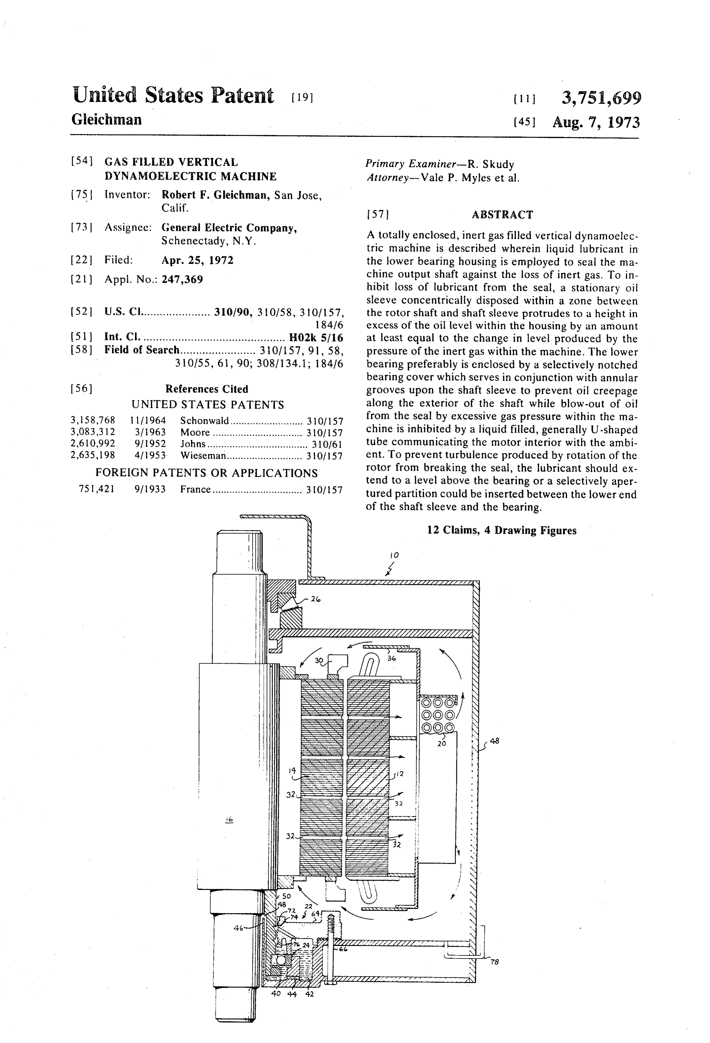
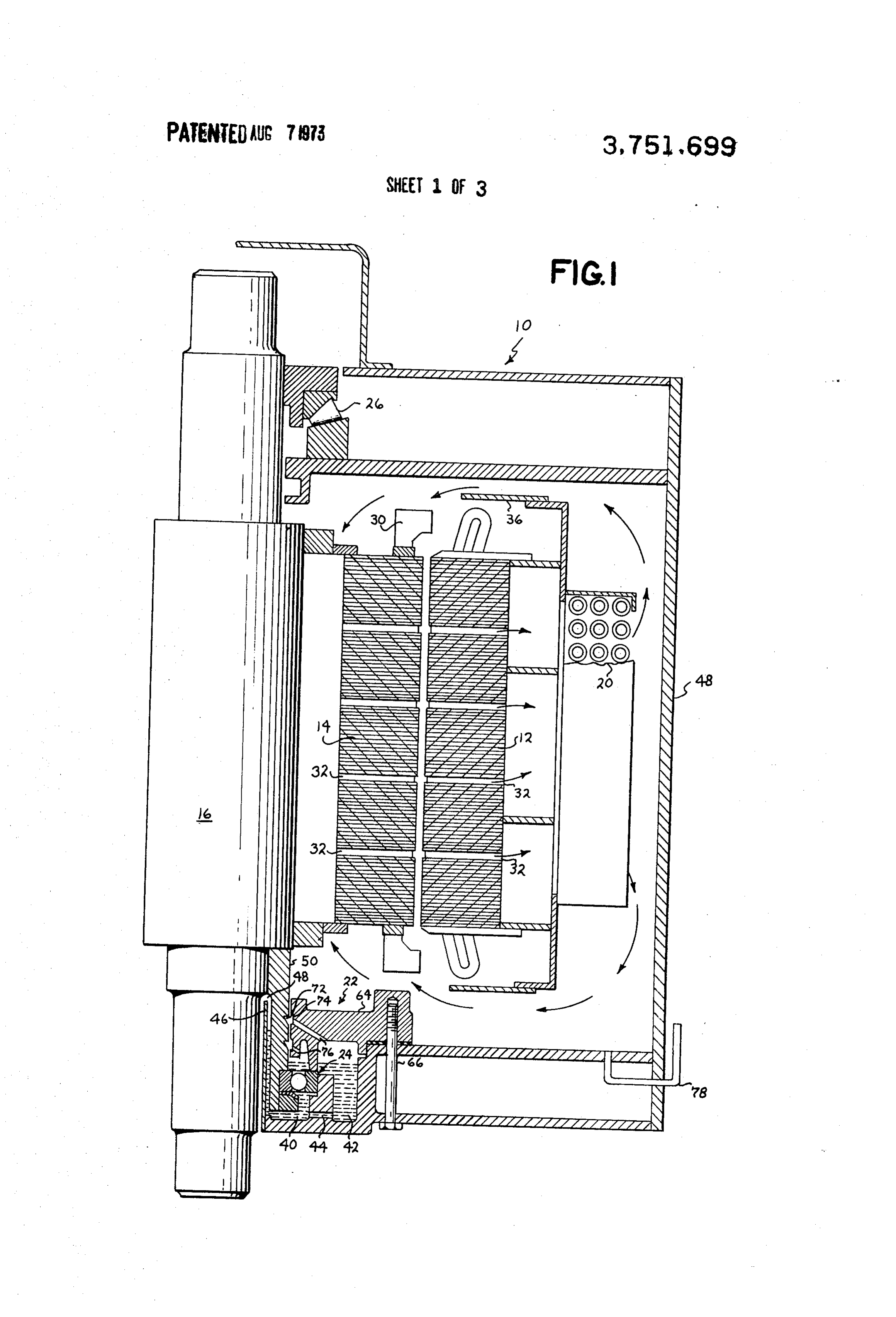
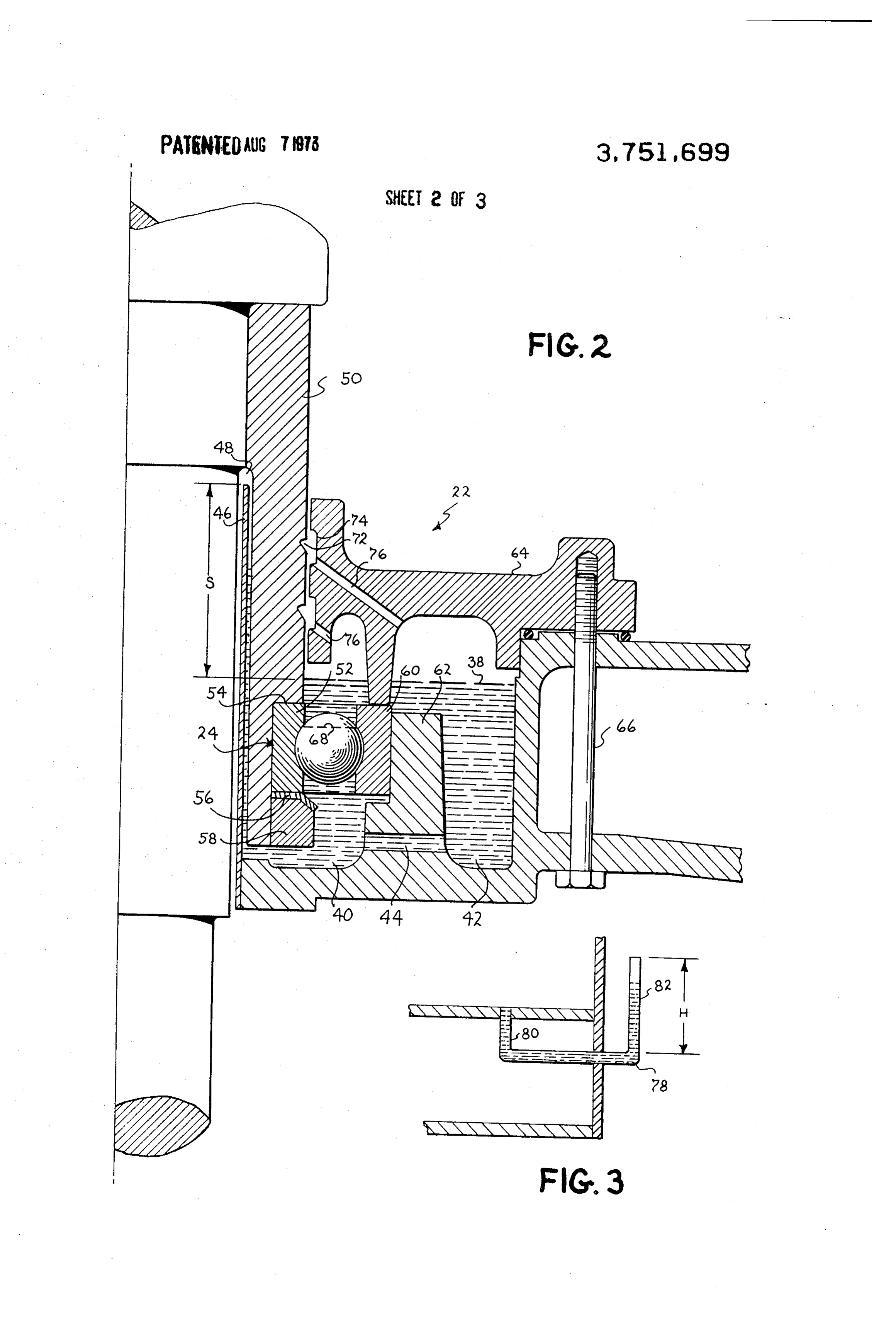
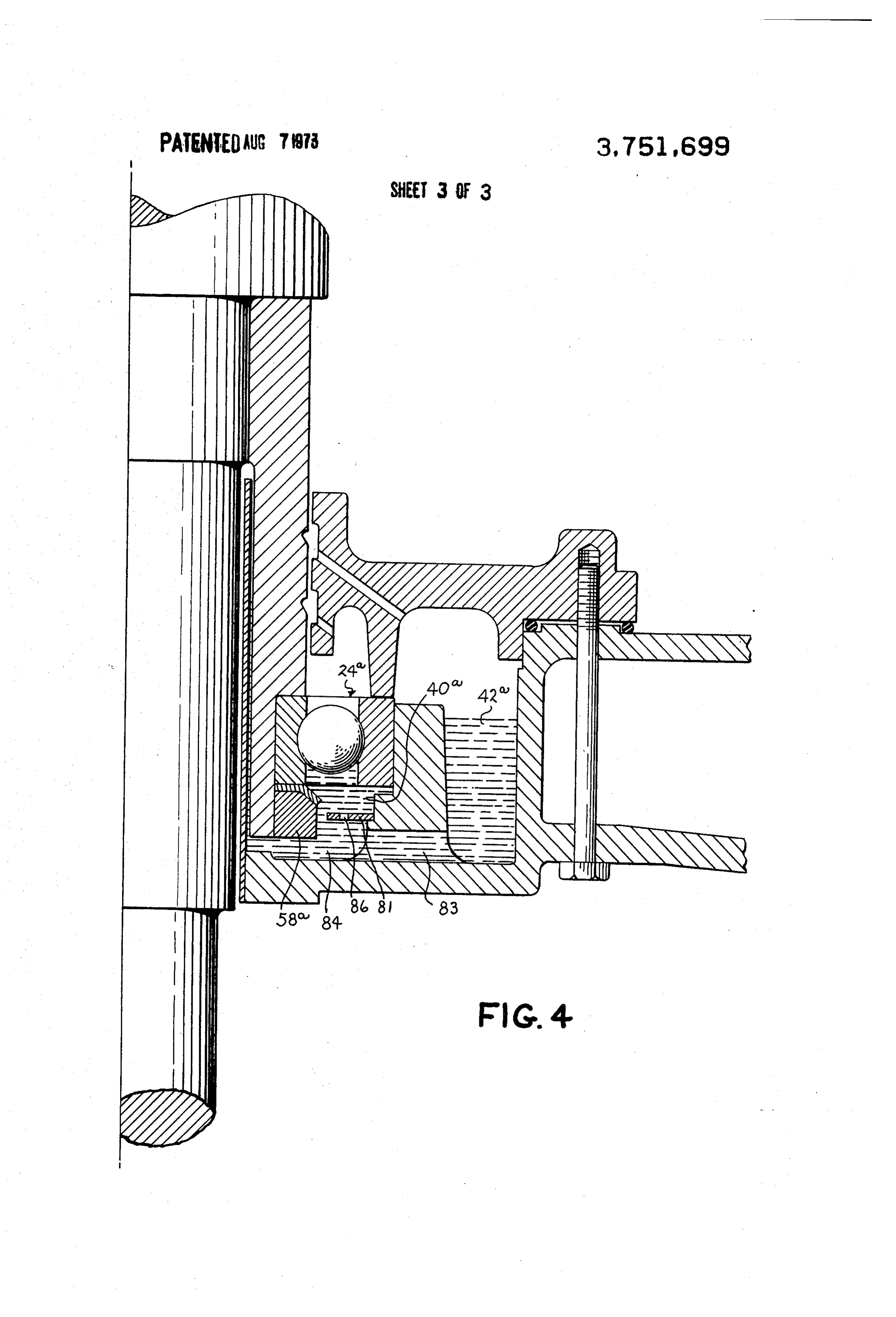
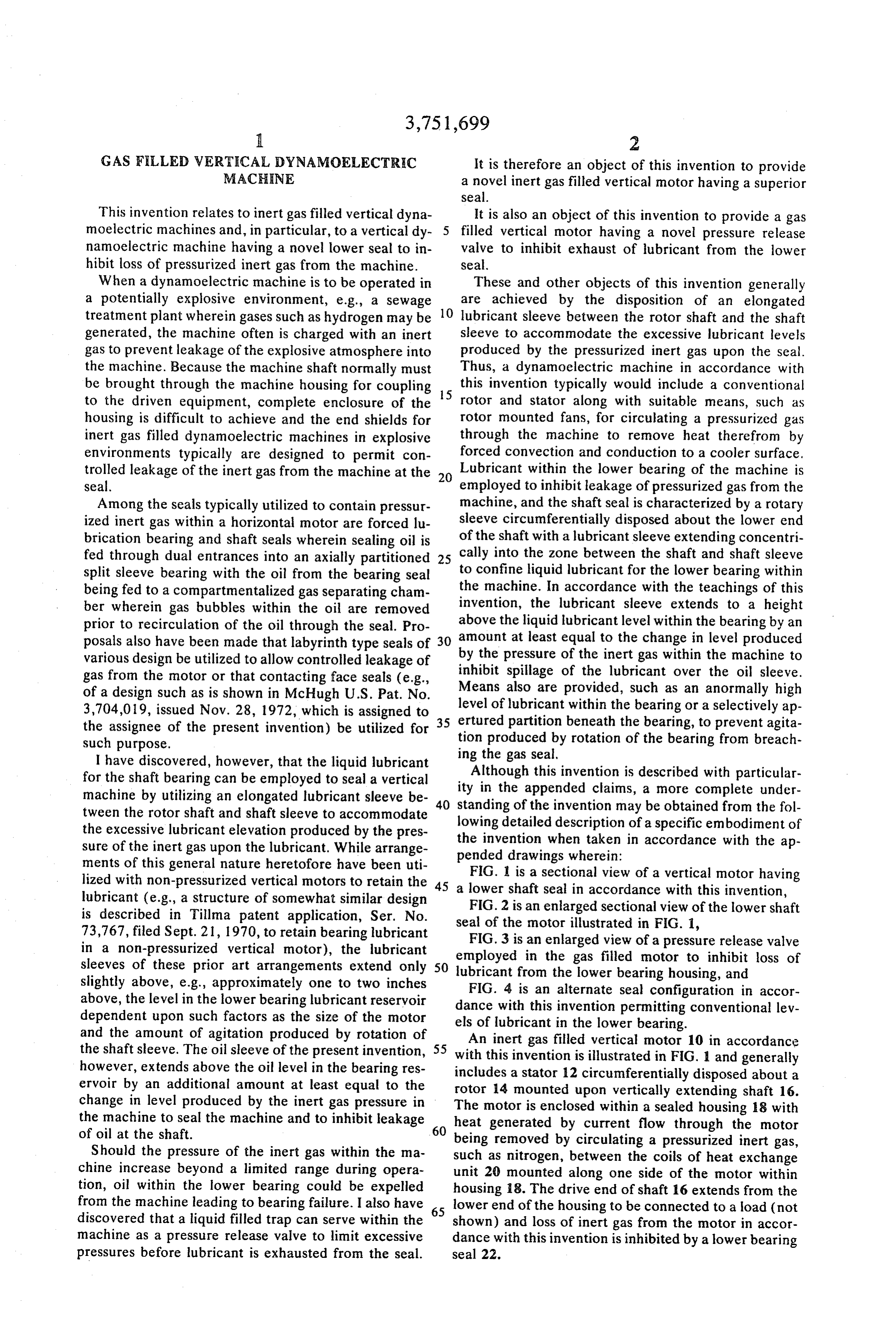
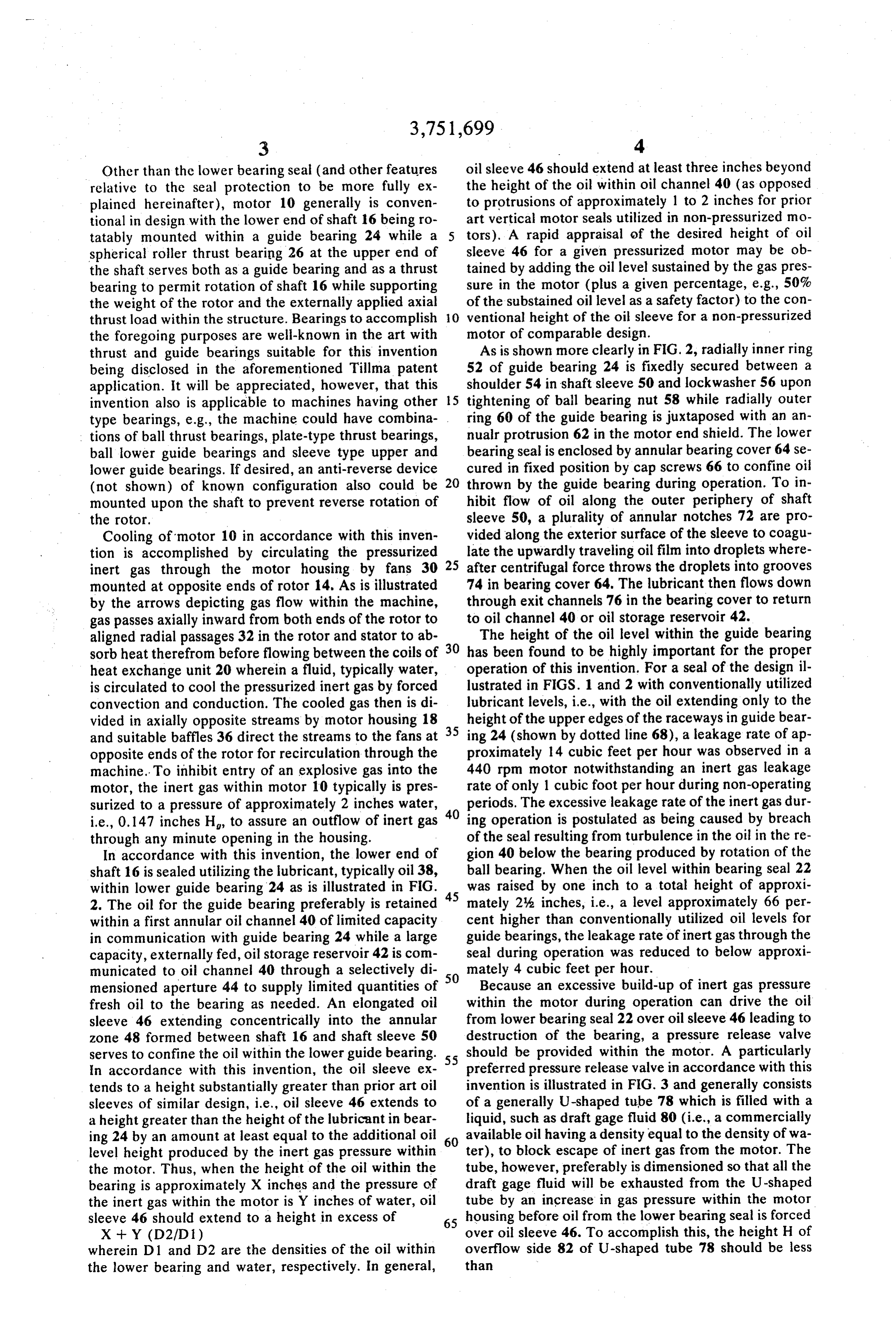
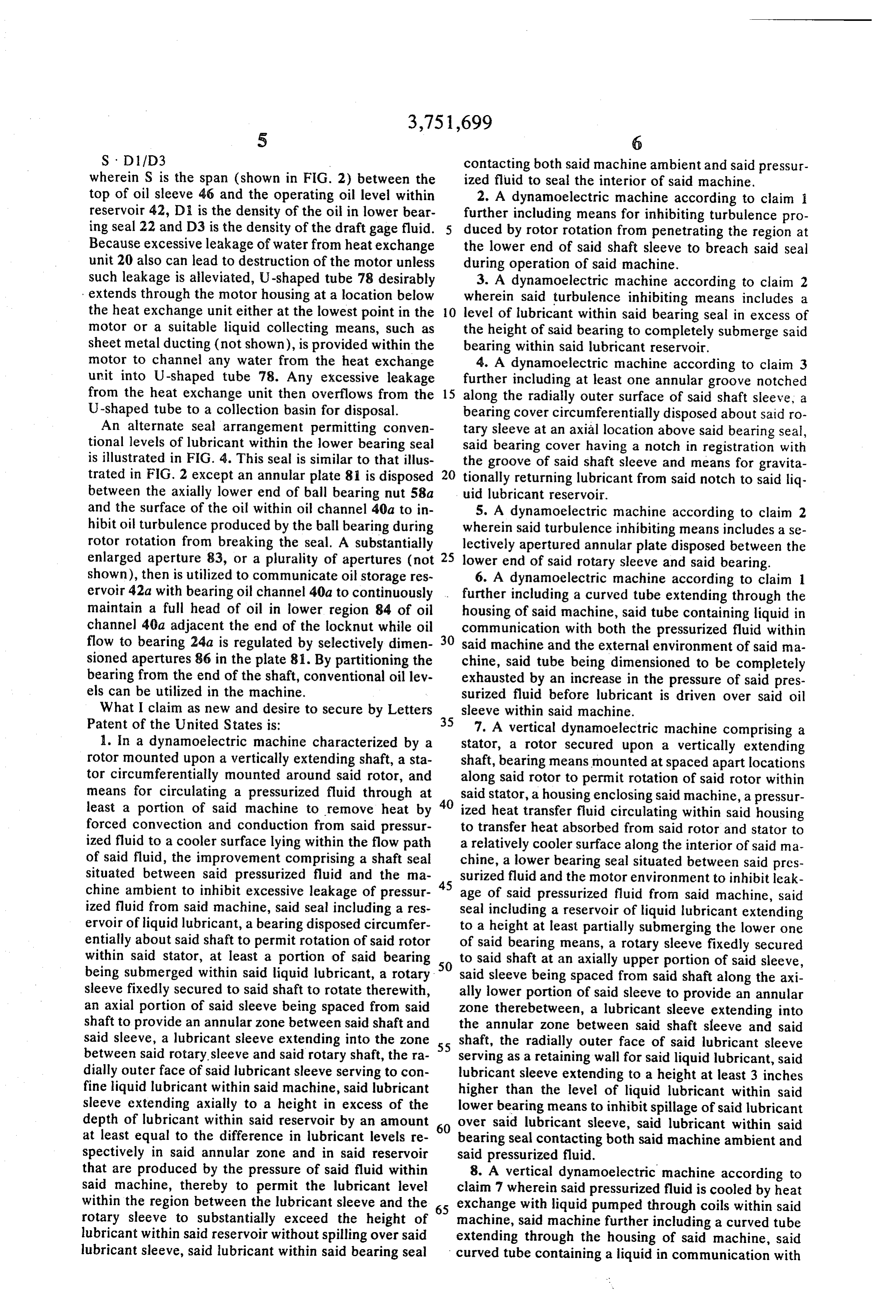
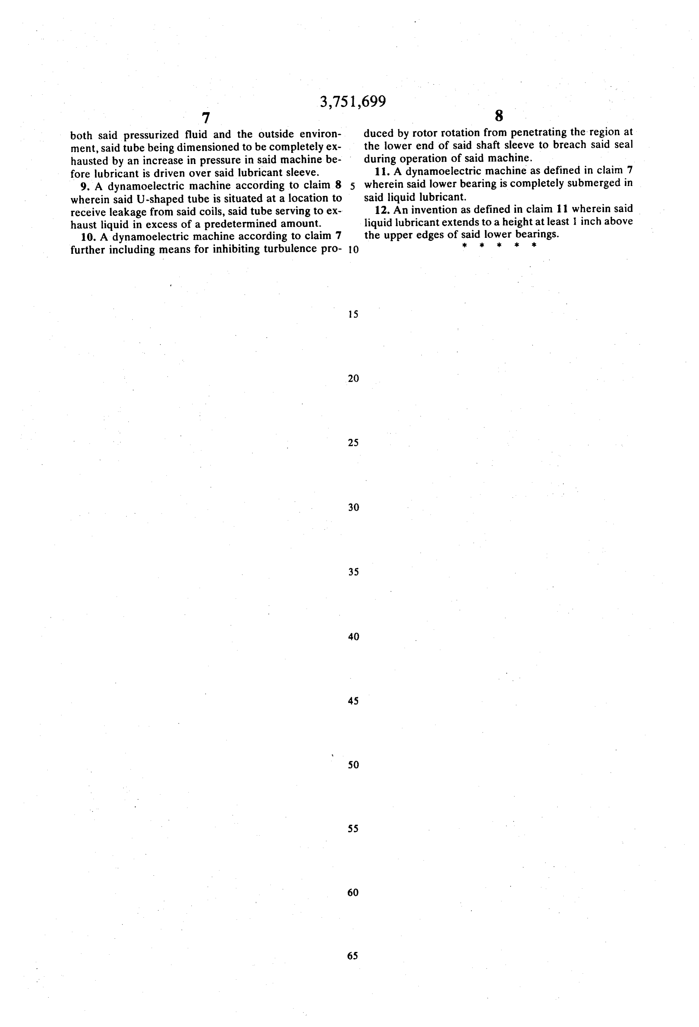
ments of this general nature heretofore have been uti FIG. 1 is a sectional view of a vertical motor having lized with non-pressurized vertical motors to retain the 45 a lower shaft seal in accordance with this invention, lubricant (e.g., a structure of somewhat similar design FIG. 2 is an enlarged sectional view of the lower shaft is described in Tillma patent application, Ser. No.
73,767, filed Sept. 21, 1970, to retain bearing lubricant seal of the motor illustrated in FIG. 1, FIG. 3 is an enlarged view of a pressure release valve in a non-pressurized vertical motor), the lubricant employed in the gas filled motor to inhibit loss of sleeves of these prior art arrangements extend only 50 lubricant from the lower bearing housing, and slightly above, e.g., approximately one to two inches FIG. 4 is an alternate seal configuration in accor above, the level in the lower bearing lubricant reservoir dance with this invention permitting conventional lev dependent upon such factors as the size of the motor els of lubricant in the lower bearing. and the amount of agitation produced by rotation of the shaft sleeve. The oil sleeve of the present invention, 55 with this invention is illustratedmotor An inert gas filled vertical
10 in accordance
FIG. 1 and generally however, extends above the oil level in the bearing res includes a stator 12 circumferentially disposed about a ervoir by an additional amount at least equal to the rotor 14 mounted upon vertically extending shaft 16. change in level produced by the inert gas pressure in The motor is enclosed within a sealed housing 18 with the machine to seal the machine and to inhibit leakage 60 heat generated by current flow through the motor of oil at the shaft. being removed by circulating a pressurized inert gas, Should the pressure of the inert gas within the ma such as nitrogen, between the coils of heat exchange chine increase beyond a limited range during opera unit 20 mounted along one side of the motor within tion, oil within the lower bearing could be expelled housing 18. The drive end of shaft 16 extends from the from the machine leading to bearing failure. I also have 65 lower end of the housing to be connected to a load (not discovered that a liquid filled trap can serve within the shown) and loss of inert gas from the motor in accor machine as a pressure release valve to limit excessive dance with this invention is inhibited by a lower bearing pressures before lubricant is exhausted from the seal. seal 22.
Page 6
Other than the lower bearing seal (and other features oil sleeve 46 should extend at least three inches beyond relative to the seal protection to be more fully ex the height of the oil within oil channel 40 (as opposed plained hereinafter), motor 10 generally is conven to protrusions of approximately 1 to 2 inches for prior tional in design with the lower end of shaft 16 being ro art vertical motor seals utilized in non-pressurized mo tatably mounted within a guide bearing 24 while a 5 tors). A rapid appraisal of the desired height of oil spherical roller thrust bearing 26 at the upper end of sleeve 46 for a given pressurized motor may be ob the shaft serves both as a guide bearing and as a thrust tained by adding the oil level sustained by the gas pres bearing to permit rotation of shaft 16 while supporting sure in the motor (plus a given percentage, e.g., 50% the weight of the rotor and the externally applied axial of the substained oil level as a safety factor) to the con thrust load within the structure. Bearings to accomplish O ventional height of the oil sleeve for a non-pressurized the foregoing purposes are well-known in the art with motor of comparable design.
thrust and guide bearings suitable for this invention As is shown more clearly in FIG. 2, radially inner ring being disclosed in the aforementioned Tillma patent 52 of guide bearing 24 is fixedly secured between a application. It will be appreciated, however, that this shoulder 54 in shaft sleeve 50 and lockwasher 56 upon invention also is applicable to machines having other 5 tightening of ball bearing nut 58 while radially outer type bearings, e.g., the machine could have combina- . ring 60 of the guide bearing is juxtaposed with an an tions of ball thrust bearings, plate-type thrust bearings, nualr protrusion 62 in the motor end shield. The lower ball lower guide bearings and sleeve type upper and bearing seal is enclosed by annular bearing cover 64 se lower guide bearings. If desired, an anti-reverse device cured in fixed position by cap screws 66 to confine oil (not shown) of known configuration also could be 20 thrown by the guide bearing during operation. To in mounted upon the shaft to prevent reverse rotation of hibit flow of oil along the outer periphery of shaft the rotor. sleeve 50, a plurality of annular notches 72 are pro Cooling of motor 10 in accordance with this inven vided along the exterior surface of the sleeve to coagul tion is accomplished by circulating the pressurized late the upwardly traveling oil film into droplets where inert gas through the motor housing by fans 30 25 after centrifugal force throws the droplets into grooves mounted at opposite ends of rotor 14. As is illustrated 74 in bearing cover 64. The lubricant then flows down by the arrows depicting gas flow within the machine, through exit channels 76 in the bearing cover to return gas passes axially inward from both ends of the rotor to to oil channel 40 or oil storage reservoir 42. aligned radial passages 32 in the rotor and stator to ab The height of the oil level within the guide bearing sorb heat therefrom before flowing between the coils of 30 has been found to be highly important for the proper heat exchange unit 20 wherein a fluid, typically water, operation of this invention. For a seal of the design il is circulated to cool the pressurized inert gas by forced lustrated in FIGS. 1 and 2 with conventionally utilized convection and conduction. The cooled gas then is di lubricant levels, i.e., with the oil extending only to the vided in axially opposite streams by motor housing 18 35 height of the upper edges of the raceways in guide bear and suitable baffles 36 direct the streams to the fans at ing 24 (shown by dotted line 68), a leakage rate of ap opposite ends of the rotor for recirculation through the proximately 14 cubic feet per hour was observed in a machine. To inhibit entry of an explosive gas into the 440 rpm motor notwithstanding an inert gas leakage motor, the inert gas within motor 10 typically is pres rate of only 1 cubic foot per hour during non-operating surized to a pressure of approximately 2 inches water, 40 periods. The excessive leakage rate of the inert gas dur i.e., 0.147 inches H, to assure an outflow of inert gas ing operation is postulated as being caused by breach through any minute opening in the housing. of the seal resulting from turbulence in the oil in the re In accordance with this invention, the lower end of gion 40 below the bearing produced by rotation of the shaft 16 is sealed utilizing the lubricant, typically oil 38, ball bearing. When the oil level within bearing seal 22 within lower guide bearing 24 as is illustrated in FIG. was raised by one inch to a total height of approxi 2. The oil for the guide bearing preferably is retained 45 mately 2% inches, i.e., a level approximately 66 per within a first annular oil channel 40 of limited capacity cent higher than conventionally utilized oil levels for in communication with guide bearing 24 while a large guide bearings, the leakage rate of inert gas through the capacity, externally fed, oil storage reservoir 42 is com seal during operation was reduced to below approxi municated to oil channel 40 through a selectively di 50 mately 4 cubic feet per hour.
mensioned aperture 44 to supply limited quantities of Because an excessive build-up of inert gas pressure fresh oil to the bearing as needed. An elongated oil within the motor during operation can drive the oil sleeve 46 extending concentrically into the annular from lower bearing seal 22 over oil sleeve 46 leading to zone 48 formed between shaft 16 and shaft sleeve 50 destruction of the bearing, a pressure release valve serves to confine the oil within the lower guide bearing. 55 should be provided within the motor. A particularly In accordance with this invention, the oil sleeve ex preferred pressure release valve in accordance with this tends to a height substantially greater than prior art oil invention is illustrated in FIG. 3 and generally consists sleeves of similar design, i.e., oil sleeve 46 extends to of a generally U-shaped tube 78 which is filled with a a height greater than the height of the lubricant in bear liquid, such as draft gage fluid 80 (i.e., a commercially ing 24 by an amount at least equal to the additional oil 60 available oil having a density equal to the density of wa level height produced by the inert gas pressure within ter), to block escape of inert gas from the motor. The the motor. Thus, when the height of the oil within the tube, however, preferably is dimensioned so that all the bearing is approximately X inches and the pressure of draft gage fluid will be exhausted from the U-shaped the inert gas within the motor is Y inches of water, oil tube by an increase in gas pressure within the motor sleeve 46 should extend to a height in excess of 65 housing before oil from the lower bearing seal is forced X + Y (D2/D1) over oil sleeve 46. To accomplish this, the height H of wherein D1 and D2 are the densities of the oil within overflow side 82 of U-shaped tube 78 should be less the lower bearing and water, respectively. In general, than
Page 7
S D1 1D3 contacting both said machine ambient and said pressur wherein S is the span (shown in FIG. 2) between the ized fluid to seal the interior of said machine. top of oil sleeve 46 and the operating oil level within 2. A dynamoelectric machine according to claim i reservoir 42, Di is the density of the oil in lower bear further including means for inhibiting turbulence pro ing seal 22 and D3 is the density of the draft gage fluid. duced by rotor rotation from penetrating the region at Because excessive leakage of water from heat exchange the lower end of said shaft sleeve to breach said seal unit 20 also can lead to destruction of the motor unless during operation of said machine. such leakage is alleviated, U-shaped tube 78 desirably 3. A dynamoelectric machine according to claim 2 extends through the motor housing at a location below wherein said turbulence inhibiting means includes a the heat exchange unit either at the lowest point in the O level of lubricant within said bearing seal in excess of motor or a suitable liquid collecting means, such as the height of said bearing to completely submerge said sheet metal ducting (not shown), is provided within the bearing within said lubricant reservoir. motor to channel any water from the heat exchange 4. A dynamoelectric machine according to claim 3 unit into U-shaped tube 78. Any excessive leakage further including at least one annular groove notched from the heat exchange unit then overflows from the 15 along the radially outer surface of said shaft sleeve, a U-shaped tube to a collection basin for disposal. bearing cover circumferentially disposed about said ro An alternate seal arrangement permitting conven tary sleeve at an axial location above said bearing seal, tional levels of lubricant within the lower bearing seal said bearing cover having a notch in registration with is illustrated in FIG. 4. This seal is similar to that illus the groove of said shaft sleeve and means for gravita trated in FIG. 2 except an annular plate 81 is disposed 20 tionally returning lubricant from said notch to said liq between the axially lower end of ball bearing nut 58a uid lubricant reservoir.
and the surface of the oil within oil channel 4.0a to in 5. A dynamoelectric machine according to claim 2 hibit oil turbulence produced by the ball bearing during wherein said turbulence inhibiting means includes a se rotor rotation from breaking the seal. A substantially lectively apertured annular plate disposed between the enlarged aperture 83, or a plurality of apertures (not 25 lower end of said rotary sleeve and said bearing. shown), then is utilized to communicate oil storage res 6. A dynamoelectric machine according to claim 1 ervoir 42a with bearing oil channel 40a to continuously further including a curved tube extending through the maintain a full head of oil in lower region 84 of oil housing of said machine, said tube containing liquid in channel 40a adjacent the end of the locknut while oil communication with both the pressurized fluid within flow to bearing 24a is regulated by selectively dimen 30 said machine and the external environment of said ma sioned apertures 86 in the plate 81. By partitioning the chine, said tube being dimensioned to be completely bearing from the end of the shaft, conventional oil lev exhausted by an increase in the pressure of said pres els can be utilized in the machine. surized fluid before lubricant is driven over said oil What I claim as new and desire to secure by Letters 35 sleeve within said machine.
Patent of the United States is: 7. A vertical dynamoelectric machine comprising a 1. In a dynamoelectric machine characterized by a stator, a rotor secured upon a vertically extending rotor mounted upon a vertically extending shaft, a sta shaft, bearing means mounted at spaced apart locations tor circumferentially mounted around said rotor, and along said rotor to permit rotation of said rotor within means for circulating a pressurized fluid through at 40 said stator, a housing enclosing said machine, a pressur least a portion of said machine to remove heat by ized heat transfer fluid circulating within said housing forced convection and conduction from said pressur to transfer heat absorbed from said rotor and stator to ized fluid to a cooler surface lying within the flow path a relatively cooler surface along the interior of said ma of said fluid, the improvement comprising a shaft seal chine, a lower bearing seal situated between said pres situated between said pressurized fluid and the ma 45 surized fluid and the motor environment to inhibit leak chine ambient to inhibit excessive leakage of pressur age of said pressurized fluid from said machine, said ized fluid from said machine, said seal including a res seal including a reservoir of liquid lubricant extending ervoir of liquid lubricant, a bearing disposed circumfer to a height at least partially submerging the lower one entially about said shaft to permit rotation of said rotor of said bearing means, a rotary sleeve fixedly secured within said stator, at least a portion of said bearing 50 to said shaft at an axially upper portion of said sleeve, being submerged within said liquid lubricant, a rotary said sleeve being spaced from said shaft along the axi sleeve fixedly secured to said shaft to rotate therewith, ally lower portion of said sleeve to provide an annular an axial portion of said sleeve being spaced from said zone therebetween, a lubricant sleeve extending into shaft to provide an annular zone between said shaft and the annular zone between said shaft sleeve and said said sleeve, a lubricant sleeve extending into the zone shaft, the radially outer face of said lubricant sleeve between said rotary, sleeve and said rotary shaft, the ra 55 serving as a retaining wall for said liquid lubricant, said dially outer face of said lubricant sleeve serving to con lubricant sleeve extending to a height at least 3 inches fine liquid lubricant within said machine, said lubricant higher than the level of liquid lubricant within said sleeve extending axially to a height in excess of the lower bearing means to inhibit spillage of said lubricant depth of lubricant within said reservoir by an amount 60 over said lubricant sleeve, said lubricant within said at least equal to the difference in lubricant levels re bearing seal contacting both said machine ambient and spectively in said annular zone and in said reservoir said pressurized fluid.
that are produced by the pressure of said fluid within 8. A vertical dynamoelectric machine according to said machine, thereby to permit the lubricant level claim 7 wherein said pressurized fluid is cooled by heat within the region between the lubricant sleeve and the 65 exchange with liquid pumped through coils within said rotary sleeve to substantially exceed the height of machine, said machine further including a curved tube lubricant within said reservoir without spilling over said extending through the housing of said machine, said lubricant sleeve, said lubricant within said bearing seal curved tube containing a liquid in communication with
Page 8
both said pressurized fluid and the outside environ duced by rotor rotation from penetrating the region at ment, said tube being dimensioned to be completely ex the lower end of said shaft sleeve to breach said seal hausted by an increase in pressure in said machine be during operation of said machine. fore lubricant is driven over said lubricant sleeve. 11. A dynamoelectric machine as defined in claim 7 9. A dynamoelectric machine according to claim 8 5 wherein said lower bearing is completely submerged in wherein said U-shaped tube is situated at a location to said12.liquid lubricant.
An invention as defined in claim 11 wherein said receive leakage from said coils, said tube serving to ex haust liquid in excess of a predetermined amount. liquid lubricant extends to a height at least 1 inch above 10. A dynamoelectric machine according to claim 7 the upper edges of said2klower k bearings.
further including means for inhibiting turbulence pro O
Provenance
- Collection
- Cited prior art
- Original PDF
- patentimages.storage.googleapis.com →
- Filed
- 1972-04-25
- Pages
- 8
- Method
- pdftotext (the PDF's own text layer) + pdftoppm 300dpi page scans
- Source
- Google Patents bibliographic record
- Granted
- 1973-08-07
- Inventors
- R Gleichman; General Electric Co
- Transcribed from
- patentimages.storage.googleapis.com →