patent · US4701379
Boron hydride polymer coated substrates
20 October 1987
Page 1 — bibliographic record
United States Patent (19) 11 Patent Number: 4,701,379 Pearson et al. (45) Date of Patent: Oct. 20, 1987 54) BORON HYDRIDE POLYMER COATED 4,266,506 5/1981 Miller ...................................... 427/6 SUBSTRATES 4,323,420 4/1982 Masnari et al. ..................... 156/633 (75) Inventors: Richard K. Pearson, Pleasanton; OTHER PUBLICATIONS Roman I. Bystroff; Dale E. Miller, Letts et al., "J. Vac. Sci. Technol”, vol. 19, No. 3, Sep.- both of Livermore, all of Calif. /Oct. 1981, pp. 739-742.
(73) Assignee: The United States of America as Primary Examiner-John H. Newsome represented by the United States Attorney, Agent, or Firm-Shyamala T. Rajender; L. E. Department of Energy, Washington, Carnahan; Judson R. Hightower
22) Filed: Aug. 27, 1986 A method is disclosed for coating a substrate with a uniformly smooth layer of a boron hydride polymer.
51 Int. Cl." ............................................... B05D 3/06 The method comprises providing a reaction chamber (52) U.S.C. .................................... 428/427; 376/151; which contains the substrate and the boron hydride 376/916; 427/6; 427/39; 428/704 plasma. A boron hydride feed stock is introduced into 58) Field of Search ......................... 427/38, 39, 41, 6; the chamber simultaneously with the generation of a 315/111.41, 111.71; 376/151,916; 428/427, 704 plasma discharge within the chamber. Aboron hydride 56) References Cited plasma of ions, electrons and free radicals which is generated by the plasma discharge interacts to form a
3,565,683 2/1971 Morelock ............................ 428/427 deposited on the substrate.
4,029,045 6/1977 Cielaszyk et al. ................... 427/251 4,091,166 5/1978 Kubacki .............................. 428/704 17 Claims, 2 Drawing Figures
Yin NS
Page 2
Drawing sheet — no readable text.
Page 3
Drawing sheet — no readable text.
Page 4
binations particularly pointed out in the appended
BORON HYDRIDE POLYMER COATED claims.
SUBSTRATES To achieve the foregoing and other objects in accor dance with the purpose of the present invention, as
The U.S. Government has rights in this invention embodied and broadly described herein, the subject pursuant to Contract No. W-7405-ENG-48 between the invention provides a method for coating a substrate or U.S. Department of Energy and the University of Cali substrates with a smooth layer of boron hydride poly fornia, for the operation of the Lawerence Livermore mer and an apparatus for generating a boron hydride National Laboratory. plasma. The method, broadly comprises, introducing at O least one solid substrate and a gas consisting essentially
FIELD OF THE INVENTION
of boron hydride into a closed container or chamber
This invention relates generally to substrates coated and applying an electric field to the chamber or con with boron hydride polymer, and more particularly to tainer to produce a gas plasma within the chamber. The those polymer coatings possessing a smooth, transpar boron hydride polymer produced thereby is deposited ent surface with a defect of no higher than about 0.1 15 on the solid substrate. Suitable solid substrates include micrometer and to applications thereof. glass and the like, hollow glass or polymer spheres BACKGROUND OF THE INVENTION being most suitable for most applications. More specifi cally, the method comprises providing an apparatus
Plasma polymerization has been widely employed for with a sealable chamber for generating a boron hydride coating various types of targets, primarily due to the 20 plasma. The chamber may be equipped with appropri uniformity of deposits on the target. To meet design ate inlets and outlets for introducing various reactants standards for ablatively driven targets capable of im or carriers or for generating a vacuum and the like. A ploding gases to high densities, the coating thickness suitable substrate (or substrates) is disposed within the must be uniform within 2 percent of the wall thickness, chamber which is then evacuated. A boron hydride void free, and smooth with few defects. 25 feedstock is introduced into the chamber. A plasma Plasma polymerization of various gaseous groups discharge is generated within the chamber simulta utilizes a gas discharge to dissociate gas molecules into neously with the introduction of the hydride feedstock ions and free radicals. The molecular fragments later into the chamber and the discharge in the chamber is recombine to form a brittle polymer coating. Previous continued to form a boron hydride plasma of ions, elec investigators have employed inductively coupled dis 30 trons and free radicals which interact to form on the charge devices operating at about 36 MHz to form substrate a layer of boron hydride polymer with a uni either fluorocarbon or hydrocarbon coatings. formly smooth surface.
Boron hydride polymers have lower molecular One aspect of the instant invention provides a sub weights than hydrocarbon polymers and hence should strate coated with an ultra smooth layer of boron hy show significantly better ablation performance. At 35 dride with surface defects of no more than about 0.1 tempts to produce boron hydride polymers have been micrometer. The apparatus for the preparation of the reported previously. These methods failed to produce a boron hydride plasma comprises wall members defining smooth surface polymer which is desirable for various a closed plasma chamber, inlet and outlet means opera applications. Such methods include the thermopyrolysis tively connected to the chamber, and means for gener of volatile borons, electric discharge, photolysis with ating a plasma discharge within the chamber. A suitable ultraviolet light, electrolysis discharge, CO2 laser arc substrate (or substrates) is disposed within the chamber, ablation of B2H6 sensitized with SF6, and shock tube the chamber is sealed off and evacuated to a pressure of adiabatic compression. about 10-6 torr. A boron hydride feedstock is intro Although hydrocarbons have been employed as coat duced into the chamber at a flow rate of about of 0.1 ings for substrates including microballoons, boron hy 45 SCCM to about 1.0 SCCM and is allowed to continue to dride polymers have a higher ablation pressure and flow into the chamber until an internal pressure of about hence are more desirable. Accordingly, it would be an 0.01 to 2.0 torr is attained within the chamber. Simulta advancement to provide boron hydride polymers which neously with the introduction of the feedstock into the possess smooth surface areas (no defect on the surface chamber, a plasma discharge is generated within the higher than about 0.1 micrometer) which can be coated 50 chamber, with the discharge continuing to form a boron on a suitable substrate such as a target microballoon. hydride plasma of ions and free radicals is formed. The SUMMARY OF THE INVENTION plasma so formed, interacts with itself to form a boron hydride polymer of the formula (BH)Y which is depos
Accordingly, an object of the present invention is to ited on the substrate as a uniformly smooth layer. The provide smooth boron hydride polymer coatings. 55 deposition occurs evenly around the substrate, and the Another object of the invention is to provide a polymer surface has no defect higher than about 0.1 method for coating a substrate with a smooth boron micrometer.
hydride polymer. Another aspect of the present invention relates to an Another object of the invention is to provide a micro article of manufacture comprising a substrate coated balloon target which is coated with a smooth boron 60 with a smooth boron hydride polymer surface. In one hydride polymer. embodiment of the invention, the substrate is a glass or Additional objects, advantages and novel features of polymer microballoon fusion target with a boron hy the invention will be set forth in part in the description dride polymer coating about 10 micrometers thick. which follows, and in part will become apparent to The boron hydride polymer coated substrates of the those skilled in the art upon examination of the follow 65 present invention are attractive alternatives to hydro ing or may be learned by practice of the invention. The carbon polymer ablated materials. Not only do they objects and advantages of the invention may be realized provide transparency in the visible region of the spec and obtained by means of the instrumentalities and com tra, enabling diagnostics of cryogenic fuel placement
Page 5
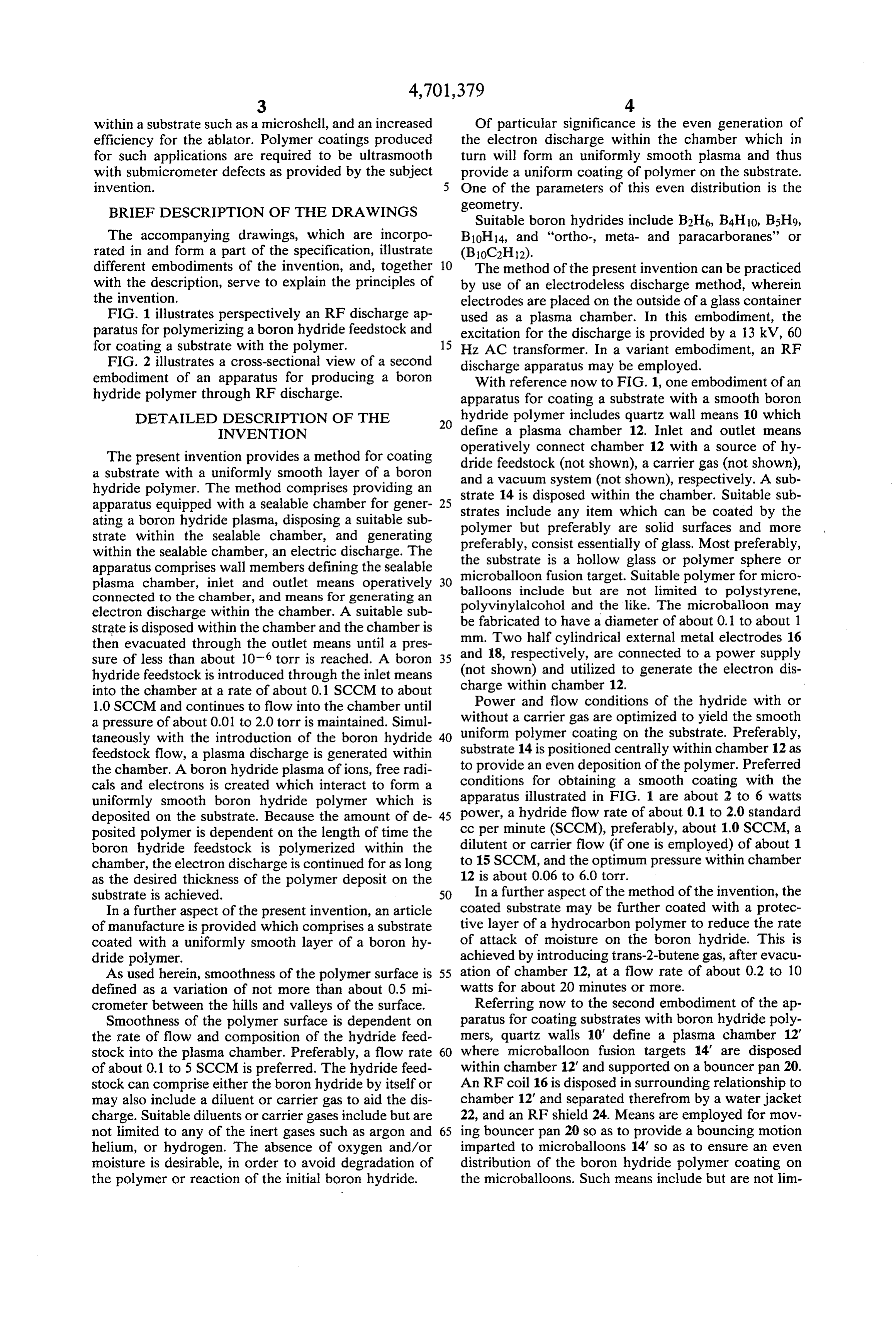
within a substrate such as a microshell, and an increased Of particular significance is the even generation of efficiency for the ablator. Polymer coatings produced the electron discharge within the chamber which in for such applications are required to be ultrasmooth turn will form an uniformly smooth plasma and thus with submicrometer defects as provided by the subject provide a uniform coating of polymer on the substrate. invention. One of the parameters of this even distribution is the BRIEF DESCRIPTION OF THE DRAWINGS geometry.
Suitable boron hydrides include B2H6, B4H10, B5H9,
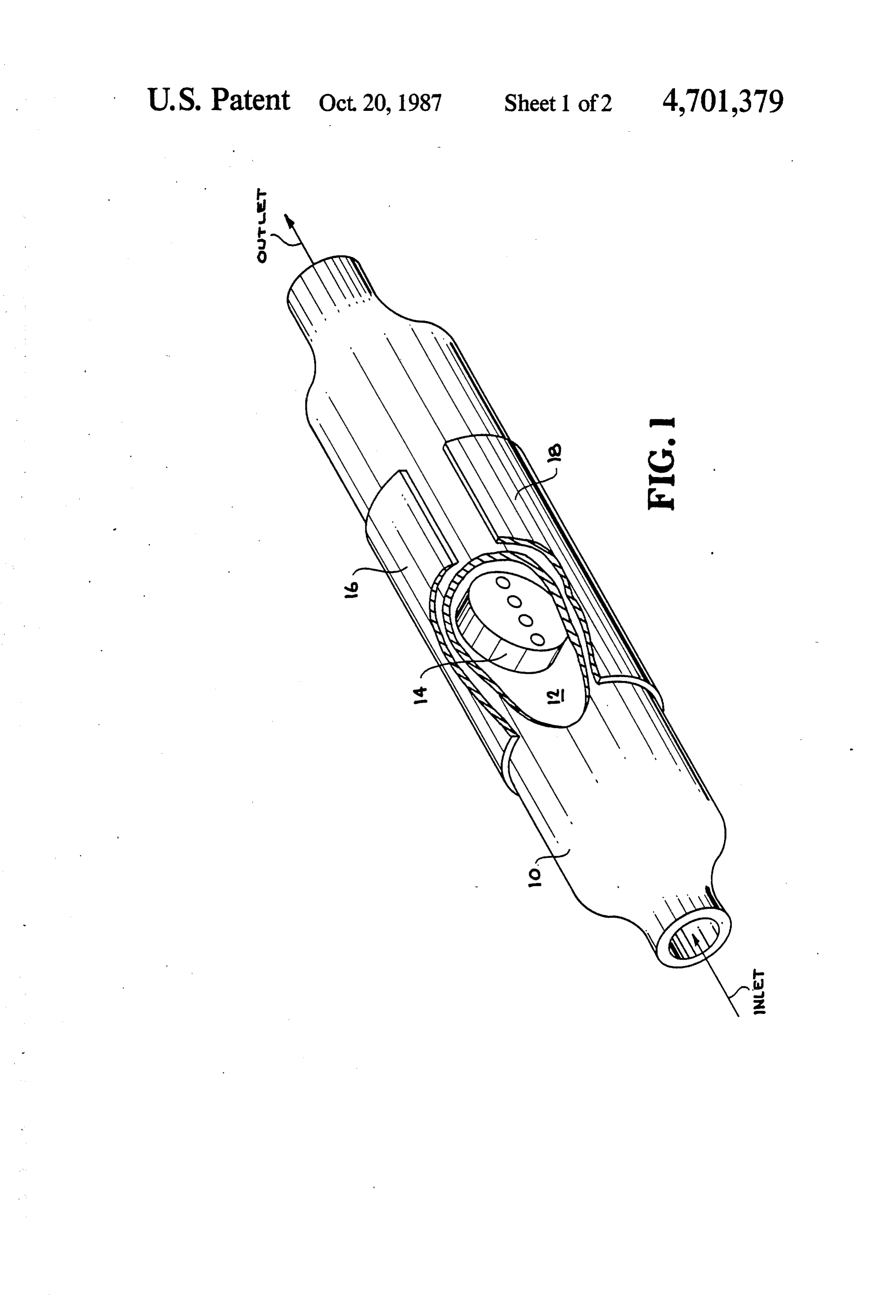
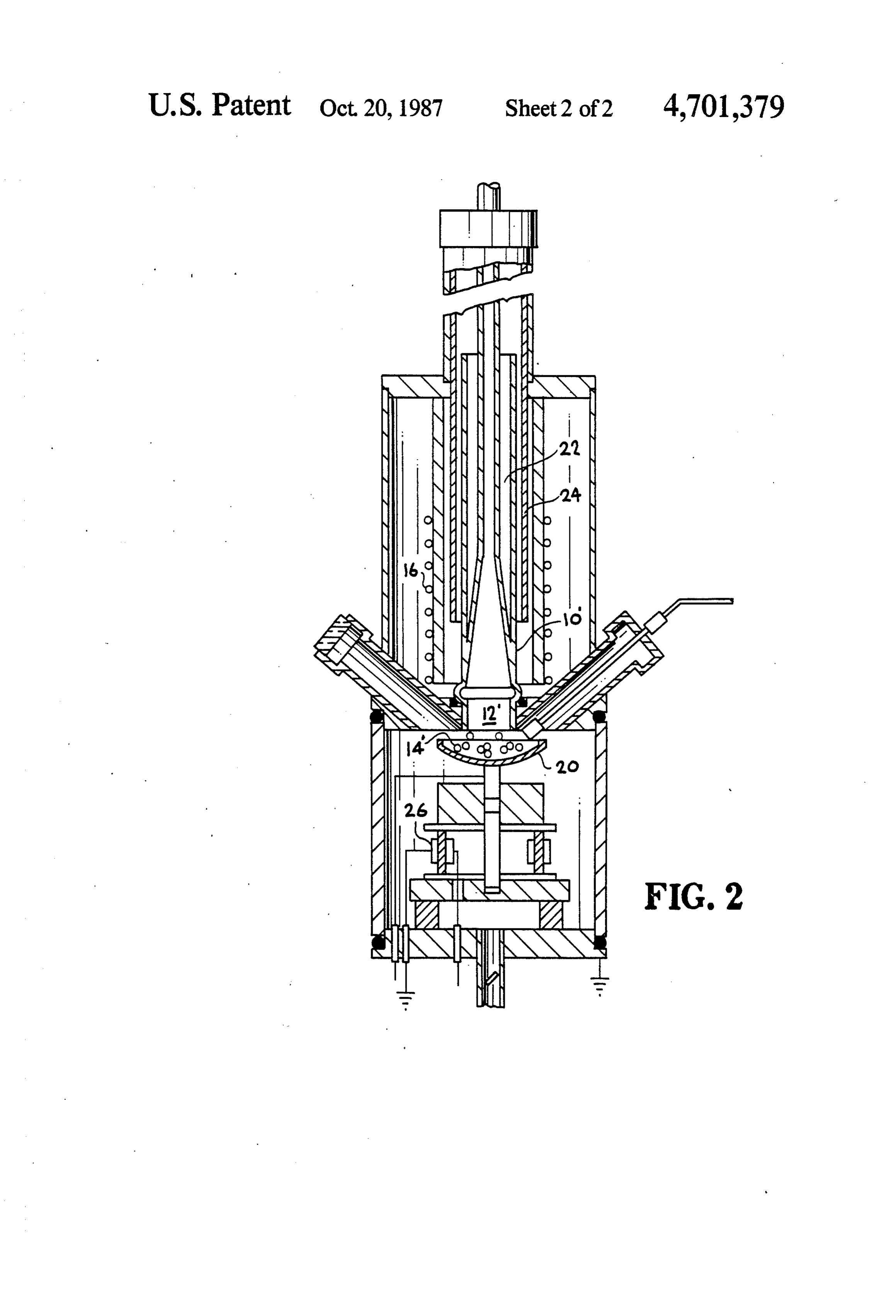
The accompanying drawings, which are incorpo B10H14, and "ortho-, meta- and paracarboranes' or rated in and form a part of the specification, illustrate (B10C2H12).
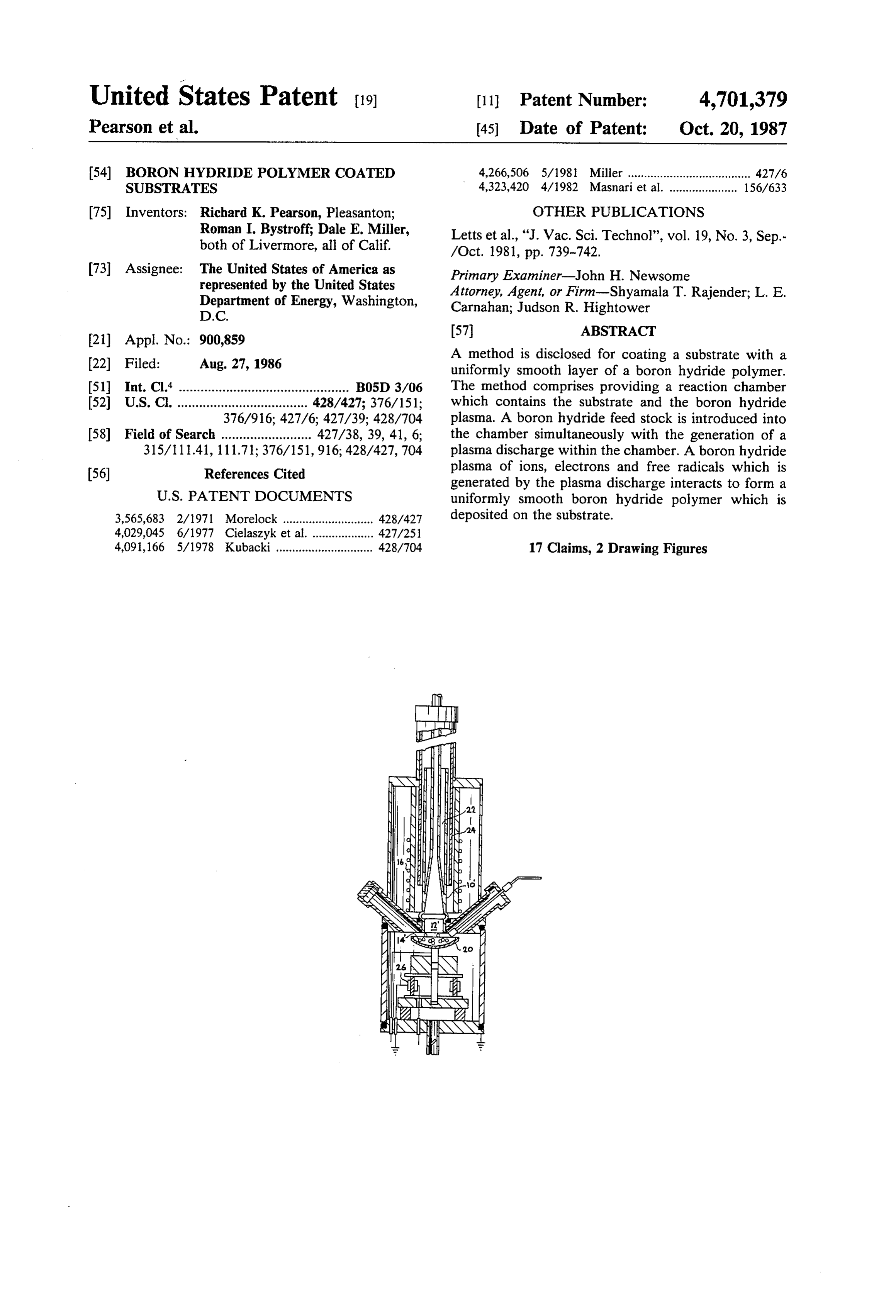
different embodiments of the invention, and, together 10 The method of the present invention can be practiced with the description, serve to explain the principles of by use of an electrodeless discharge method, wherein the invention. electrodes are placed on the outside of a glass container FIG. 1 illustrates perspectively an RF discharge ap used as a plasma chamber. In this embodiment, the paratus for polymerizing a boron hydride feedstock and excitation for the discharge is provided by a 13 kV, 60 for coating a substrate with the polymer. 15 Hz AC transformer. In a variant embodiment, an RF FIG. 2 illustrates a cross-sectional view of a second discharge apparatus may be employed. embodiment of an apparatus for producing a boron With reference now to FIG. 1, one embodiment of an hydride polymer through RF discharge. apparatus for coating a substrate with a smooth boron DETAILED DESCRIPTION OF THE hydride polymer includes quartz wall means 10 which INVENTION define a plasma chamber 12. Inlet and outlet means The present invention provides a method for coating operatively connect chamber 12 with a source of hy a substrate with a uniformly smooth layer of a boron dride feedstock (not shown), a carrier gas (not shown), hydride polymer. The method comprises providing an and a vacuum system (not shown), respectively. A sub apparatus equipped with a sealable chamber for gener strate 25 14 is disposed within the chamber. Suitable sub ating a boron hydride plasma, disposing a suitable sub polymerinclude strates but any item which can be coated by the preferably are solid surfaces and more strate within the sealable chamber, and generating preferably, consist essentially of glass. Most preferably, within the sealable chamber, an electric discharge. The the substrate is a hollow glass or polymer sphere or apparatus comprises wall members defining the sealable microballoon fusion target. Suitable polymer for micro plasma chamber, inlet and outlet means operatively balloons include but are not limited to polystyrene, connected to the chamber, and means for generating an polyvinylalcohol and the like. The microballoon may electron discharge within the chamber. A suitable sub be fabricated to have a diameter of about 0.1 to about strate is disposed within the chamber and the chamber is mm. Two half cylindrical external metal electrodes 161 then evacuated through the outlet means until a pres sure of less than about 10-6 torr is reached. A boron 35 and 18, respectively, are connected to a power supply hydride feedstock is introduced through the inlet means (not shown) and utilized to generate the electron dis into the chamber at a rate of about 0.1 SCCM to about charge within chamber 12.
1.0. SCCM and continues to flow into the chamber until Power and flow conditions of the hydride with or a pressure of about 0.01 to 2.0 torr is maintained. Simul without a carrier gas are optimized to yield the smooth taneously with the introduction of the boron hydride 40 uniform polymer coating on the substrate. Preferably, feedstock flow, a plasma discharge is generated within substrate 14 is positioned centrally within chamber 12 as the chamber. A boron hydride plasma of ions, free radi to provide an even deposition of the polymer. Preferred cals and electrons is created which interact to form a conditions for obtaining a smooth coating with the uniformly smooth boron hydride polymer which is apparatus illustrated in FIG. 1 are about 2 to 6 watts deposited on the substrate. Because the amount of de 45 power, a hydride flow rate of about 0.1 to 2.0 standard posited polymer is dependent on the length of time the cc per minute (SCCM), preferably, about 1.0 SCCM, a boron hydride feedstock is polymerized within the dilutent or carrier flow (if one is employed) of about 1 chamber, the electron discharge is continued for as long to 15 SCCM, and the optimum pressure within chamber as the desired thickness of the polymer deposit on the 12 is about 0.06 to 6.0 torr.
substrate is achieved. 50 In a further aspect of the method of the invention, the In a further aspect of the present invention, an article coated substrate may be further coated with a protec of manufacture is provided which comprises a substrate tive layer of a hydrocarbon polymer to reduce the rate coated with a uniformly smooth layer of a boron hy of attack of moisture on the boron hydride. This is dride polymer. achieved by introducing trans-2-butenegas, after evacu As used herein, smoothness of the polymer surface is 55 ation of chamber 12, at a flow rate of about 0.2 to 10 defined as a variation of not more than about 0.5 mi watts for about 20 minutes or more. crometer between the hills and valleys of the surface. Referring now to the second embodiment of the ap Smoothness of the polymer surface is dependent on paratus for coating substrates with boron hydride poly the rate of flow and composition of the hydride feed mers, quartz walls 10' define a plasma chamber 12' stock into the plasma chamber. Preferably, a flow rate 60 where microballoon fusion targets 14 are disposed of about 0.1 to 5 SCCM is preferred. The hydride feed within chamber 12" and supported on a bouncer pan 20. stock can comprise either the boron hydride by itself or An RF coil 16 is disposed in surrounding relationship to may also include a diluent or carrier gas to aid the dis chamber 12' and separated therefrom by a water jacket charge. Suitable diluents or carrier gases include but are 22, and an RF shield 24. Means are employed for mov not limited to any of the inert gases such as argon and 65 ing bouncer pan 20 so as to provide a bouncing motion helium, or hydrogen. The absence of oxygen and/or imparted to microballoons 14' so as to ensure an even moisture is desirable, in order to avoid degradation of distribution of the boron hydride polymer coating on the polymer or reaction of the initial boron hydride. the microballoons. Such means include but are not lim
Page 6
ited to a piezoelectrically driven motorized apparatus TABLE I-continued
The following examples are meant to illustrate vari Diborane-Argon Experiment ous embodiments of the present invention, and are not Experiment i4 Experiment 15 deemed to limit the invention which is defined in the Power appended claims. 2.4-3 watts 6 watts
EXAMPLE 1.
Diborane Feedstock:
In each case, after discharge ceased, trans-2-butene
O (without argon) was introduced into the discharge
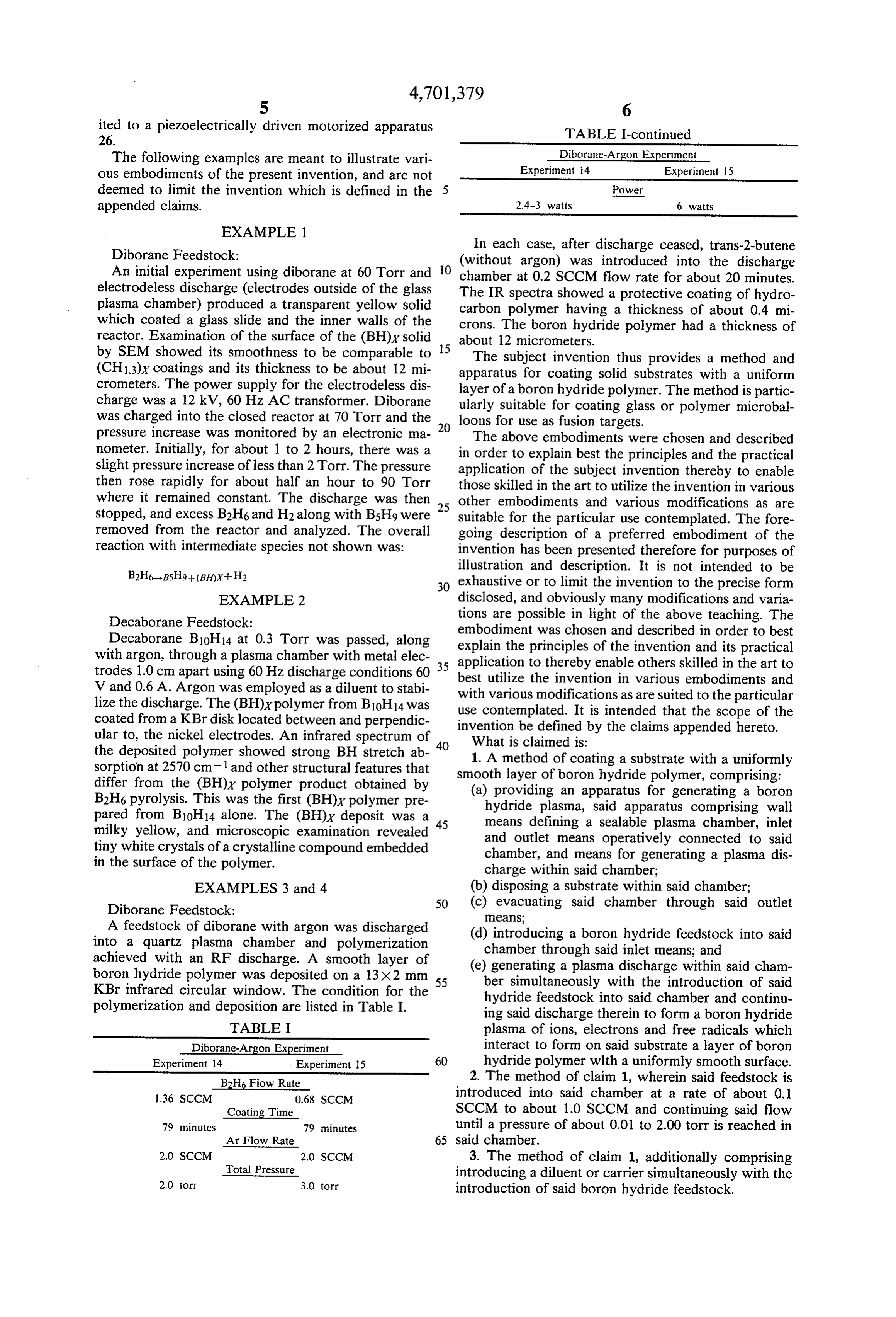
An initial experiment using diborane at 60 Torr and chamber at 0.2 SCCM flow rate for about 20 minutes. electrodeless discharge (electrodes outside of the glass The IR spectra showed a protective coating of hydro plasma chamber) produced a transparent yellow solid carbon polymer having a thickness of about 0.4 mi which coated a glass slide and the inner walls of the crons. The boron hydride polymer had a thickness of reactor. Examination of the surface of the (BH)x solid about 12 micrometers.
by SEM showed its smoothness to be comparable to 5 The subject invention thus provides a method and (CH13)x coatings and its thickness to be about 12 mi apparatus for coating solid substrates with a uniform crometers. The power supply for the electrodeless dis layer of a boron hydride polymer. The method is partic charge was a 12 kV, 60 Hz AC transformer. Diborane ularly suitable for coating glass or polymer microbal was charged into the closed reactor at 70 Torr and the loons for use as fusion targets.
pressure increase was monitored by an electronic ma The above embodiments were chosen and described nometer. Initially, for about 1 to 2 hours, there was a in order to explain best the principles and the practical slight pressure increase of less than 2 Torr. The pressure application of the subject invention thereby to enable then rose rapidly for about half an hour to 90 Torr those skilled in the art to utilize the invention in various where it remained constant. The discharge was then 25 other embodiments and various modifications as are stopped, and excess B2H6 and H2 along with Bsh9 were suitable for the particular use contemplated. The fore removed from the reactor and analyzed. The overall going description of a preferred embodiment of the reaction with intermediate species not shown was: invention has been presented therefore for purposes of illustration and description. It is not intended to be 30 exhaustive or to limit the invention to the precise form
EXAMPLE 2 disclosed, and obviously many modifications and varia Decaborane Feedstock: tions are possible in light of the above teaching. The embodiment was chosen and described in order to best
Decaborane Bloh 14 at 0.3 Torr was passed, along explain the principles of the invention and its practical with argon, through a plasma chamber with metal elec 35 application trodes 1.0 cm apart using 60 Hz discharge conditions 60 best utilize to thereby enable others skilled in the art to the invention in various embodiments and
V and 0.6 A. Argon was employed as a diluent to stabi with various modifications as are suited to the particular lize the discharge. The (BH)Ypolymer from B10H14 was use contemplated. It is intended that the scope of the coated from a KBr disk located between and perpendic invention ular to, the nickel electrodes. An infrared spectrum of 40 What isbeclaimed defined by the claims appended hereto.
the deposited polymer showed strong BH stretch ab 1. A method of coating a substrate with a uniformly sorption at 2570 cm 1 and other structural features that smooth layer of boron hydride polymer, comprising: differ from the (BH)x polymer product obtained by (a) providing an apparatus for generating a boron B2H6 pyrolysis. This was the first (BH)x polymer pre hydride plasma, said apparatus comprising wall pared from B10H14 alone. The (BH)x deposit was a 45 means defining a sealable plasma chamber, inlet milky yellow, and microscopic examination revealed and outlet means operatively connected to said tiny white crystals of a crystalline compound embedded chamber, and means for generating a plasma dis in the surface of the polymer. charge within said chamber; EXAMPLES 3 and 4 (b) disposing a substrate within said chamber; Diborane Feedstock: 50 (c) evacuating said chamber through said outlet means;
A feedstock of diborane with argon was discharged (d) introducing a boron hydride feedstock into said into a quartz plasma chamber and polymerization chamber through said inlet means; and achieved with an RF discharge. A smooth layer of (e) generating a plasma discharge within said cham boron hydride polymer was deposited on a 13X2 mm 55 ber simultaneously with the introduction of said KBr infrared circular window. The condition for the polymerization and deposition are listed in Table I. hydride feedstock into said chamber and continu ing said discharge therein to form a boron hydride
TABLE I plasma of ions, electrons and free radicals which Diborane-Argon Experiment interact to form on said substrate a layer of boron Experiment 14 . Experiment 15 60 hydride polymer wlth a uniformly smooth surface. B2H6 Flow Rate 2. The method of claim 1, wherein said feedstock is 1.36 SCCM 0.68 SCCM introduced into said chamber at a rate of about 0.1 Coating Time SCCM to about 1.0 SCCM and continuing said flow 79 minutes 79 minutes until a pressure of about 0.01 to 2.00 torr is reached in
2.0. SCCM 2.0 SCCM 3. The method of claim 1, additionally comprising Total Pressure introducing a diluent or carrier simultaneously with the 2.0 torr 3.0 torr introduction of said boron hydride feedstock.
Page 7
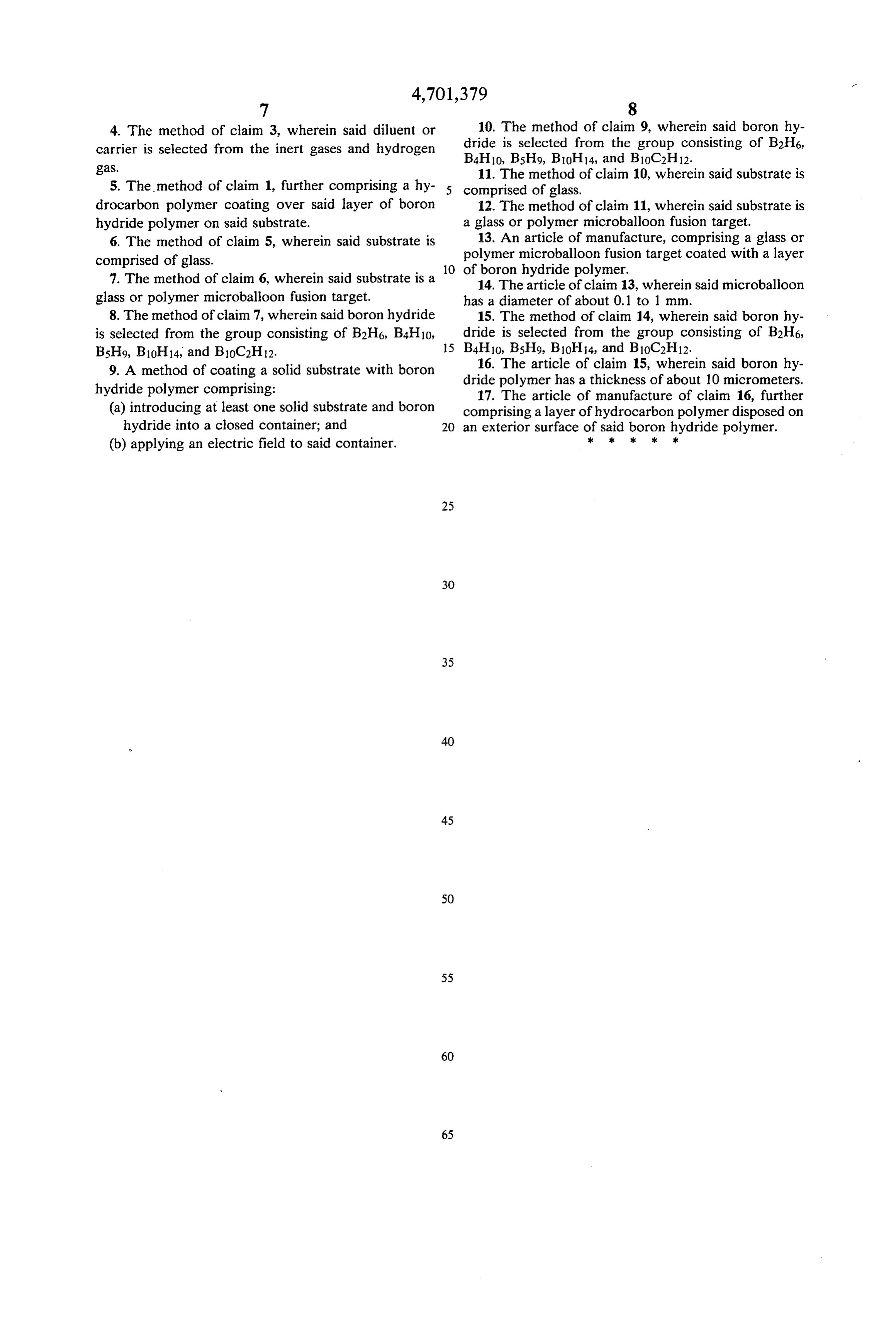
4. The method of claim 3, wherein said diluent or 10. The method of claim 9, wherein said boron hy carrier is selected from the inert gases and hydrogen dride is selected from the group consisting of B2H6, gas.
11. The method of claim 10, wherein said substrate is 5. The method of claim 1, further comprising a hy comprised of glass.
drocarbon polymer coating over said layer of boron 12. The method of claim 11, wherein said substrate is hydride polymer on said substrate. a glass or polymer microballoon fusion target. 6. The method of claim 5, wherein said substrate is 13. An article of manufacture, comprising a glass or comprised of glass. polymer microballoon fusion target coated with a layer 10 of boron hydride polymer.
7. The method of claim 6, wherein said substrate is a 14. The article of claim 13, wherein said microballoon glass or polymer microballoon fusion target. has a diameter of about 0.1 to 1 mm. 8. The method of claim 7, wherein said boron hydride 15. The method of claim 14, wherein said boron hy is selected from the group consisting of B2H6, B4H10, dride is selected from the group consisting of B2H6, B5H9, B10H14, and B10C2H12. 15 B4H10, B5H9, B10H14, and B10C2H12. 9. A method of coating a solid substrate with boron dride 16. The article of claim 15, wherein said boron hy hydride polymer comprising: polymer has a thickness of about 10 micrometers. 17. The article of manufacture of claim 16, further (a) introducing at least one solid substrate and boron comprising a layer of hydrocarbon polymer disposed on hydride into a closed container; and 20 an exterior surface of said boron hydride polymer.
(b) applying an electric field to said container.
Provenance
- Collection
- Cited prior art
- Original PDF
- patentimages.storage.googleapis.com →
- Filed
- 1986-08-27
- Pages
- 7
- Method
- pdftotext (the PDF's own text layer) + pdftoppm 300dpi page scans
- Source
- Google Patents bibliographic record
- Granted
- 1987-10-20
- Inventors
- Richard K. Pearson; Roman I. Bystroff; Dale E. Miller; US Department of Energy
- Transcribed from
- patentimages.storage.googleapis.com →