patent · US2142612
Boiler
3 January 1939
Page 1
Drawing sheet — no readable text.
Page 2
Drawing sheet — no readable text.
Page 3
Drawing sheet — no readable text.
Page 4
Drawing sheet — no readable text.
Page 5
Patented Jan. 3, 1939 2,142,612
BOLER
Charles E. Lucke, New York, N. Y., assignor to
The Babcock & Wilcox Company, Bayonne,
N. J., a corporation of New Jersey
Original application January 3, 1927, Serial No.
158,470. Divided and this application August
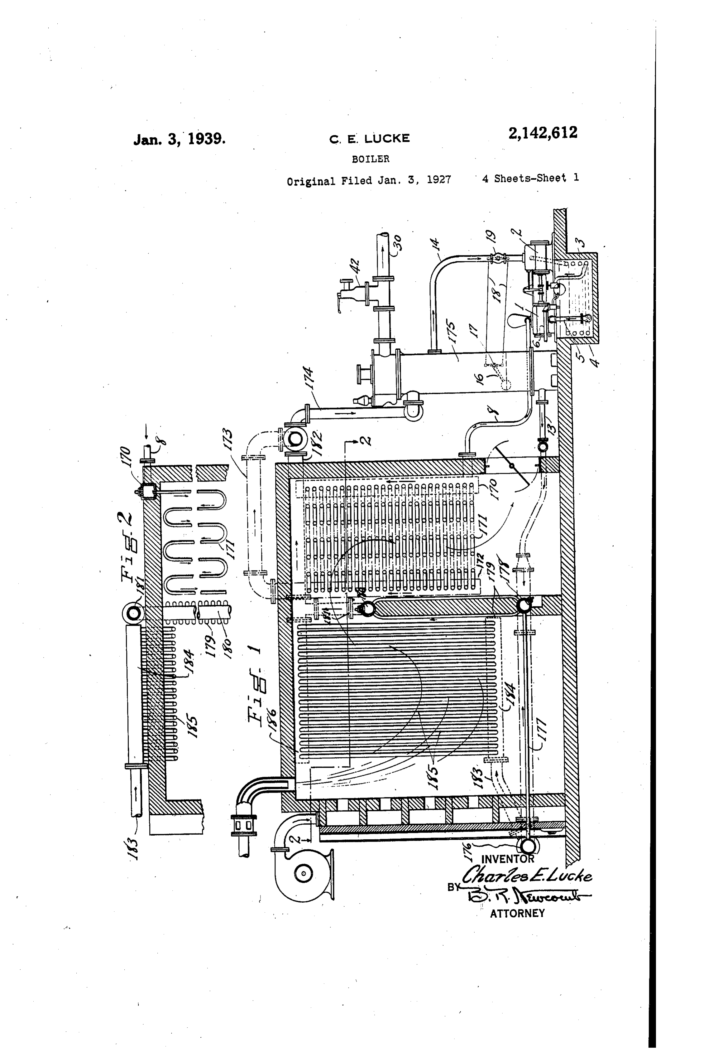
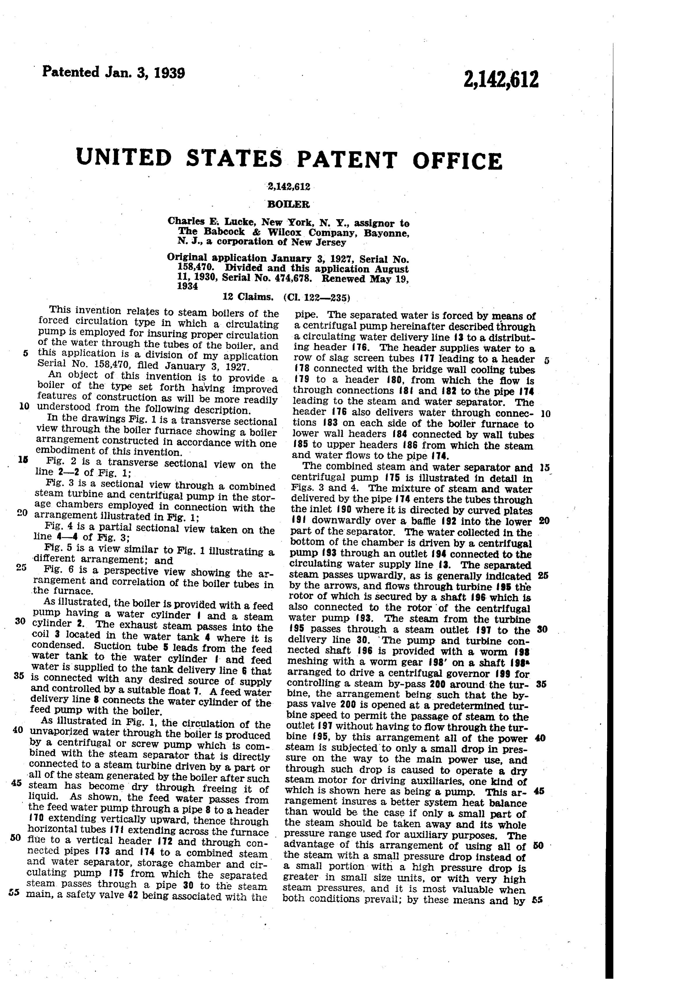
This invention relates to steam boilers of the pipe. The separated water is forced by means of forced circulation type in which a circulating a centrifugal pump hereinafter described through pump is employed for insuring proper circulation a circulating water delivery line 3 to a distribut of the water through the tubes of the boiler, and ing header 76. The header supplies water to a 5 this application is a division of my application
Serial No. 158,470, filed January 3, 1927. row of slag screen tubes 77 leading to a header 5 f 78 connected with the bridge wall cooling tubes
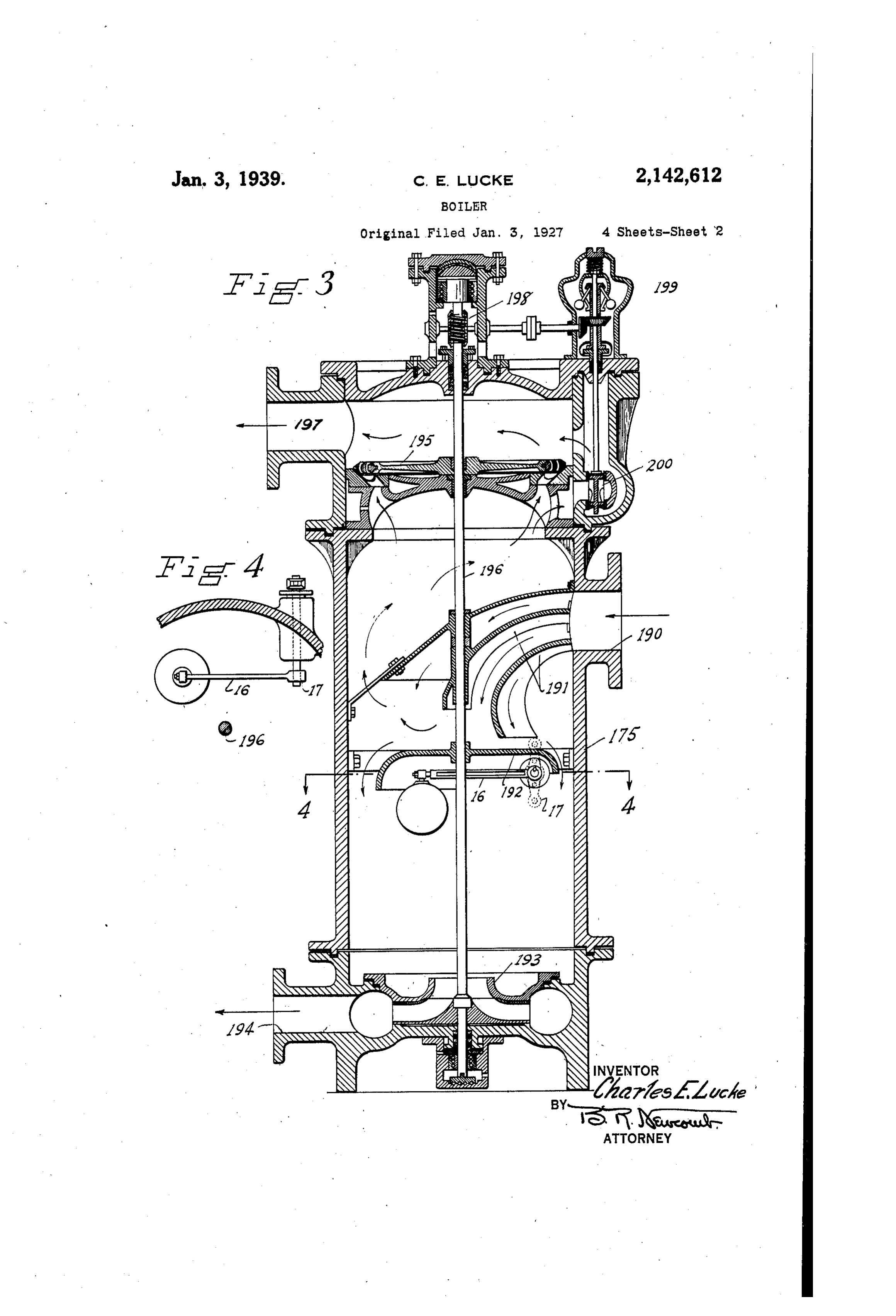
An object of this invention is to provide a 79 to a header 80, from which the flow is boiler of the type set forth having improved through connections 8 and 82 to the pipe 4 features of construction as will be more readily 0 understood from the following description. leading to the steam and water separator. The In the drawings Fig. 1 is a transverse sectional header 76 also delivers water through connec O tions 83 on each side of the boiler furnace to view through the boiler furnace showing a boiler lower wall headers 84 connected by wall tubes arrangement Constructed in accordance with one 85 to upper headers 86 from which the steam embodiment of this invention. and water flows to the pipe 74. 5 Fig. 2 is a transverse sectional view on the line 2-2 of Fig. 1; - The combined steam and water separator and 5 Fig. 3 is a sectional view through a combined centrifugal pump 75 is illustrated in detail in Steam turbine and centrifugal pump in the stor Figs. 3 and 4. The mixture of steam and water age chambers employed in connection with the delivered by the pipe 74 enters the tubes through arrangement illustrated in Fig. 1; the inlet 90 where it is directed by curved plates Fig. 4 is a partial sectional view taken on the 9 downwardly over a baffle 92 into the lower line 4-4 of Fig. 3; part of the separator. The water collected in the bottom of the chamber is driven by a centrifugal
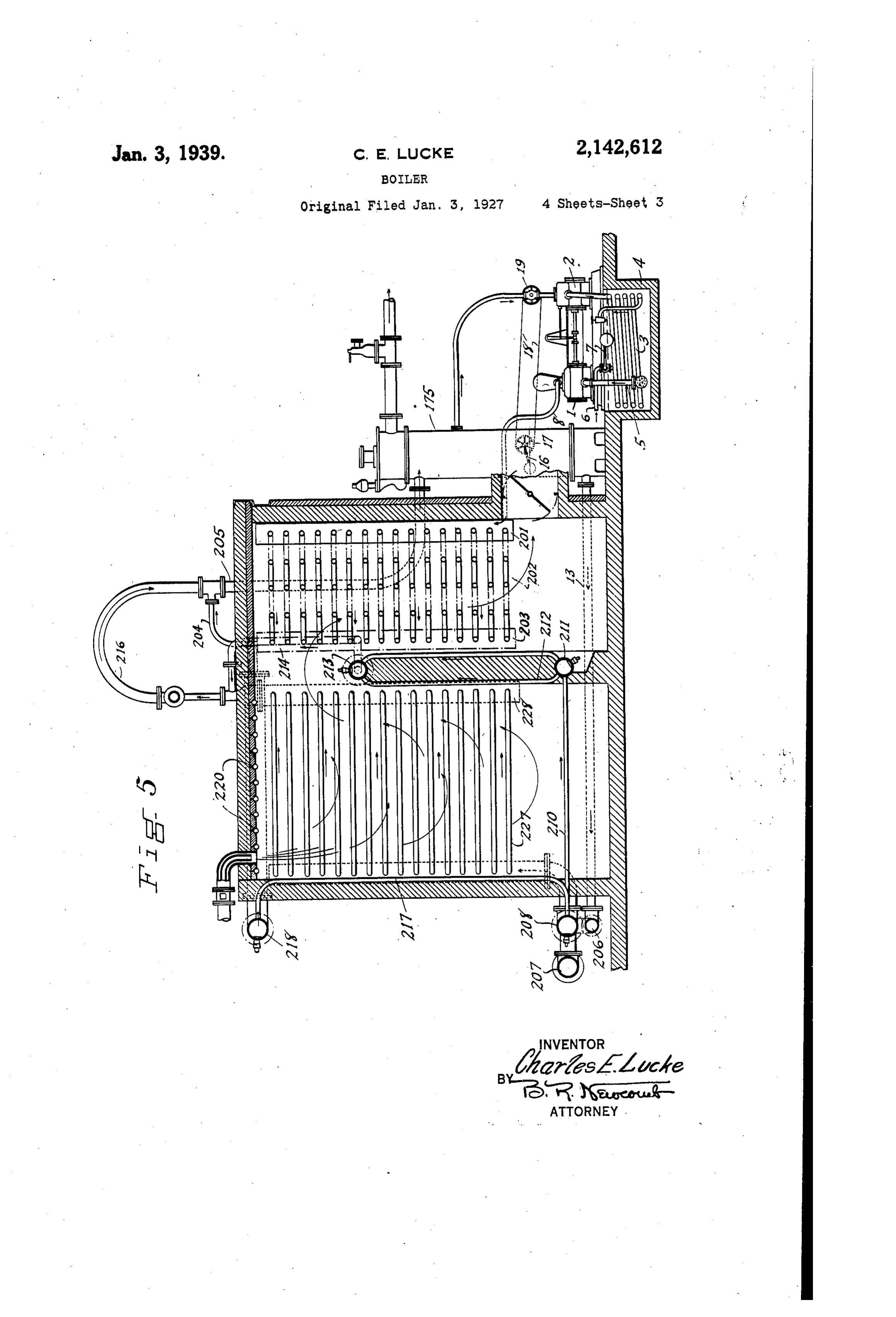
Fig. 5 is a view similar to Fig. 1 illustrating a pump f 93 through an outlet 94 connected to the different arrangement; and
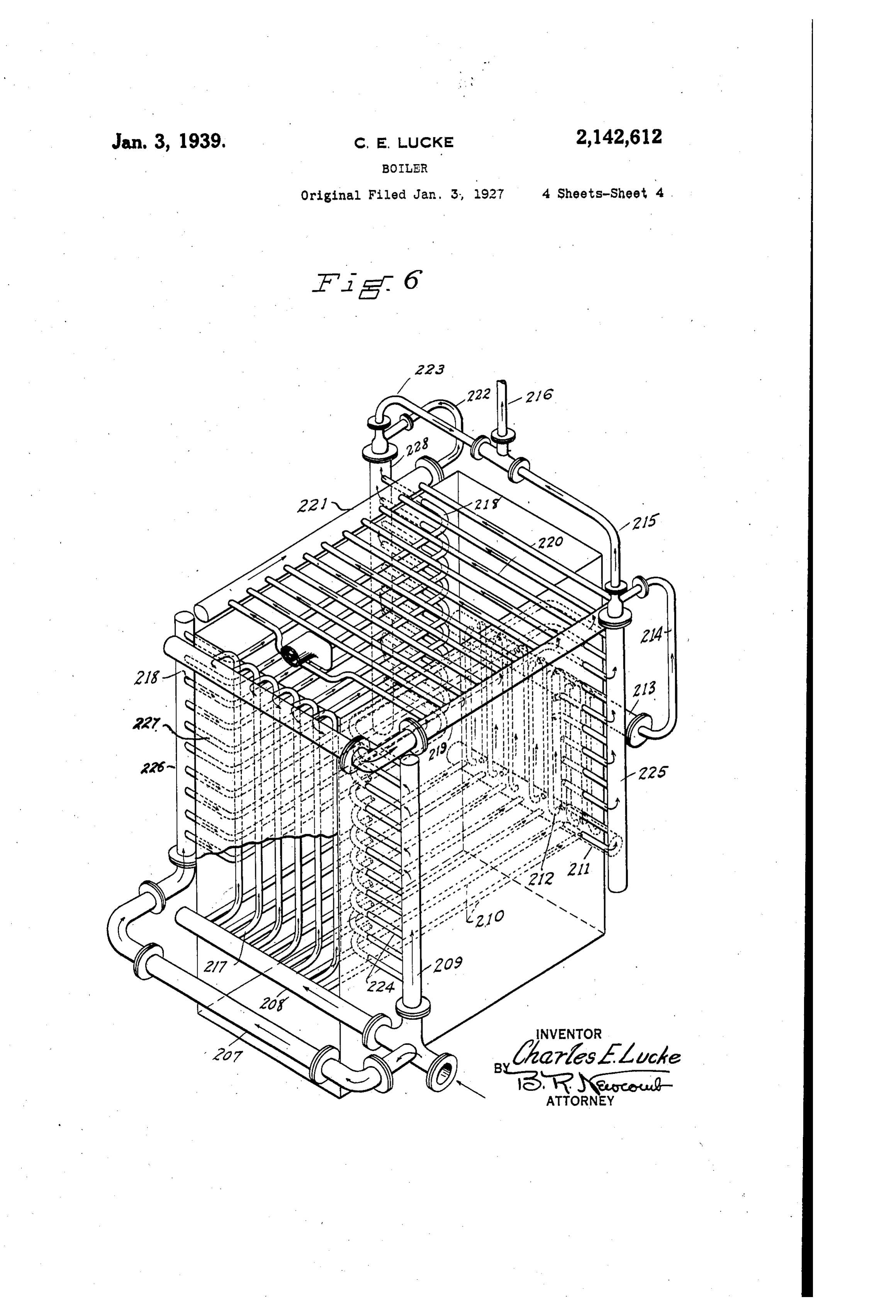
Fig. 6 is a perspective view showing the ar circulating water supply line 3. The separated rangement and correlation of the boiler tubes in steam passes upwardly, as is generally indicated by the arrows, and flows through turbine 95 the the furnace.
rotor of which is secured by a shaft 96 which is
As illustrated, the boiler is provided with a feed also connected to the rotor of the centrifugal pump having a water cylinder and a steam 30 cylinder 2. The exhaust steam passes into the water pump f 93. The steam from the turbine coil 3 located in the water tank 4 where it is delivery 195 passes through a steam outlet f 97 to the condensed. Suction tube 5 leads from the feed nected shaft line 30. The pump and turbine con Water tank to the water cylinder f. and feed meshing with a96worm is provided with a worm fs gear 98' on a shaft 98
Water is Supplied to the tank delivery line 6 that arranged to drive a centrifugal governor 99 for is connected with any desired source of supply controlling a steam by-pass 200 around the tur 35 and controlled by a suitable float 7. A feed water bine, the arrangement being such that the by delivery line 8 connects the water cylinder of the pass valve 200 is opened at a predetermined tur feed pump with the boiler. bine speed to permit the passage of steam to the As illustrated in Fig. 1, the circulation of the outlet 97 without having to flow through the tur 40 unvaporized water through the boiler is produced bine f 95, by this arrangement all of the power by a centrifugal or screw pump which is com steam bined with the steam separator that is directly sure onis the subjected to only a small drop in pres connected to a steam turbine driven by a part or through suchway to the main power use, and drop is caused to operate a dry all of the steam generated by the boiler after such 45 Steam has become dry through freeing it of steam motor for driving auxiliaries, one kind of liquid. As shown, the feed water passes from which is shown here as being a pump. This ar 45 the feed water pump through a pipe 8 to a header than wouldinsures rangement a better system heat balance be the case if only a small part of
To extending vertically upward, thence through the steam should be taken away and its whole horizontal tubes extending across the furnace 50 flue to a vertical header 72 and through con pressure range used for auxiliary purposes. The advantage of this arrangement of using all of nected pipes 73 and 74 to a combined steam the steam with a small pressure drop instead of and Water separator, storage chamber and cir culating pump 75 from which the separated agreater Small portion with a high pressure drop is in small size units, or with very high steam passes through a pipe 30 to the steam. steam pressures, and it is most valuable when main, a Safety valve 42 being associated with the both conditions prevail; by these means and by
Page 6
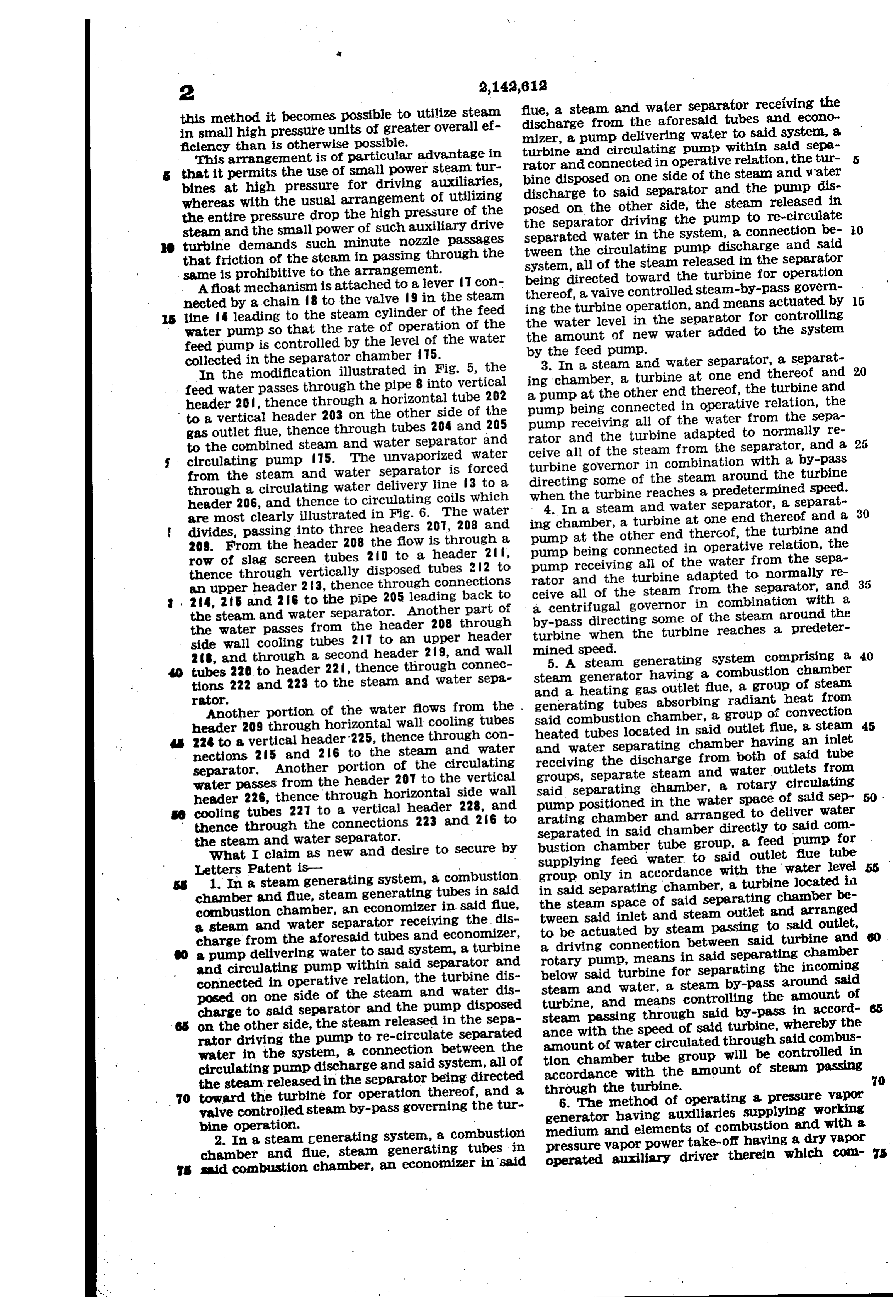
this method it becomes possible to utilize steam flue, a steam and water separator receiving the in small high pressure units of greater overall ef discharge from the aforesaid tubes and econo mizer, a pump delivering water to said system, a ficiency than is otherwise possible. turbine and circulating pump within said sepa This arrangement is of particular advantage in rator and connected in operative relation, the tur that it permits the use of small power steam tur bine disposed on one side of the steam and water bines at high pressure for driving auxiliaries, discharge to said separator and the pump dis whereas with the usual arrangement of utilizing posed on the other side, the steam released in the entire pressure drop the high pressure of the the separator driving the pump to re-circulate steam and the small power of such auxiliary drive separated water in the System, a connection be 0. O turbine demands such minute nozzle passages tween the circulating pump discharge and said that friction of the steam in passing through the system, all of the steam released in the separator same is prohibitive to the arrangement. being directed toward the turbine for operation Afloat mechanism is attached to a lever 7 con thereof, a waive controlled steam-by-pass govern nected by a chain f3 to the valve 9 in the steam ing the turbine operation, and means actuated by 15 s line 4 leading to the steam cylinder of the feed the water level in the separator for controlling Water pump So that the rate of operation of the the amount of new water added to the System feed pump is controlled by the level of the water by the feed pump.
collected in the separator chamber 75. 3. In a steam and water separator, a separat 20 In the modification illustrated in Fig. 5, the ing chamber, a turbine at one end thereof and feed water passes through the pipe 8 into vertical a pump at the other end thereof, the turbine and header 20, thence through a horizontal tube 202 pump being connected in operative relation, the to a vertical header 203 on the other side of the pump receiving all of the water from the sepa gas outlet fue, thence through tubes 204 and 205 rator and the turbine adapted to normally re to the combined steam and water separator and ceive all of the steam from the separator, and a 25 circulating pump 75. The unvaporized water turbine governor in combination with a by-pass from the steam and Water separator is forced directing some of the steam around the turbine through a circulating water delivery line f3 to a when the turbine reaches a predetermined speed. header 206, and thence to circulating coils which 4. In a steam and water separator, a separat are most clearly illustrated in Fig. 6. The water ing chamber, a turbine at one end thereof and a 30 divides, passing into three headers 207, 208 and pump at the other end thereof, the turbine and 209. From the header 208 the flow is through a pump being connected in operative relation, the row of slag screen tubes 20 to a header 2 f, pump receiving all of the water from the sepa thence through vertically disposed tubes 22 to rator and the turbine adapted to normally re an upper header 23, thence through connections ceive all of the steam from the separator, and 24, 25 and 26 to the pipe 205 leading back to a centrifugal governor in combination with a the steam and water separator. Another part of by-pass directing some of the steam around the the water passes from the header 208 through turbine when the turbine reaches a predeter side wall cooling tubes 27 to an upper header mined speed.
28, and through a second header 29, and wall 5. A steam generating System comprising a 40 tubes 220 to header 22, thence through connec steam generator having a combustion chamber tions 222 and 223 to the steam and water sepa and a heating gas outlet flue, a group of steam Another portion of the water flows from the generating rator. tubes absorbing radiant heat from header 209 through horizontal wall cooling tubes said combustion chamber, a group of convection 45 224 to a vertical header 225, thence through con heated tubes located in said outlet flue, a steam nections 25 and 26 to the steam and water and water separating chamber having an inlet receiving the discharge from both of said tube separator. Another portion of the circulating groups, separate steam and water outlets from water passes from the header 207 to the vertical said separating chamber, a rotary circulating header 226, thence through horizontal side wall pump positioned in cooling tubes 227 to a vertical header 228, and arating chamber andthearranged water space of Said Sep to deliver water thence through the connections 223 and 26 to separated in said chamber directly to said com the steam and water Separator. bustion chamber tube group, a feed pump for What I claim as new and desire to Secure by supplying feed water to said outlet flue tube 55 Letters 1. In aPatent steamis generating System, a combustion. group only in accordance with the water level chamber and fue, Steam generating tubes in Said in said separating chamber, a turbine located in the steam space of said separating chamber be combustion chamber, an economizer in said flue, tween said inlet and steam outlet and arranged a steam and water separator receiving the dis to be actuated by steam passing to said outlet, charge from the aforesaid tubes and economizer, a driving connection between said turbine and a pump delivering water to saud System, a turbine and circulating pump within said separator and rotary below pump, means in said separating chamber said turbine for separating the incoming connected in operative relation, the turbine dis steam and water, a steam by-pass around said posed on one side of the steam and water dis turbine, and means controlling the amount of charge to said separator and the pump disposed steam passing through said by-pass in accord on the other side, the steam released in the sepa ance with the speed of said turbine, whereby the rator driving the pump to re-circulate separated amount of water circulated through said combus water in the system, a connection between the tion chamber tube group will be controlled in circulating pump discharge and said system, all of accordance with the amount of steam passing 70 the steam released in the separator being directed through the turbine.
70 toward the turbine for operation thereof, and a valve controlled steam by-pass governing the tur 6. The method of operating a pressure vapor generator having auxiliaries supplying working bine operation. medium and elements of combustion and with a 2. In a steam generating system, a combustion pressure vapor power take-off having a dry vapor chamber and flue, steam generating tubes in operated auxiliary driver therein which Com S s said combustion chamber, an economizer in said
Page 7
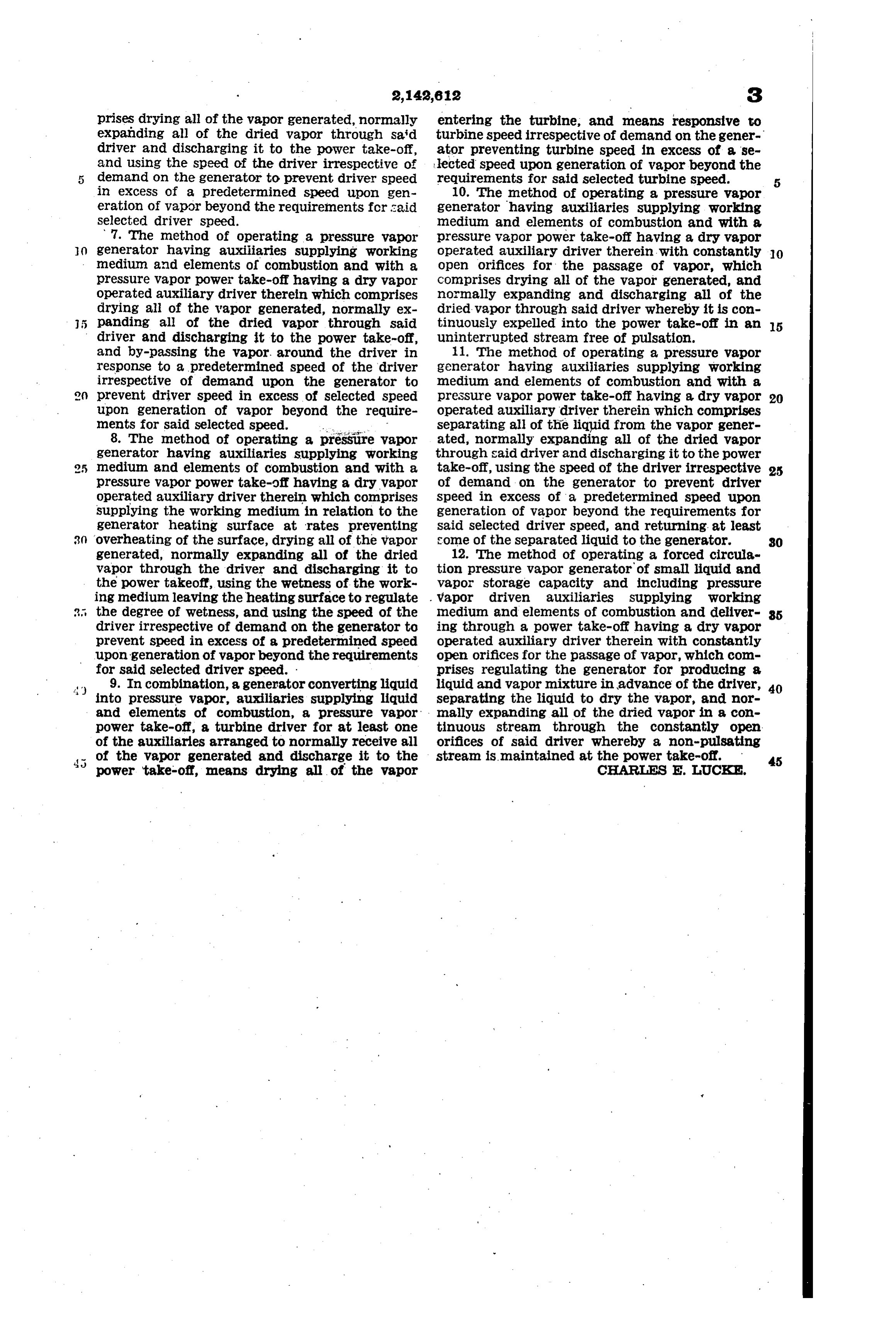
prises drying all of the vapor generated, normally entering the turbine, and means responsive to expanding all of the dried vapor through said turbine speed irrespective of demand on the gener driver and discharging it to the power take-off, ator preventing turbine speed in excess of a se and using the speed of the driver irrespective of lected Speed upon generation of vapor beyond the demand on the generator to prevent driver speed requirements for said selected turbine speed. in excess of a predetermined speed upon gen 10. The method of operating a pressure vapor eration of vapor beyond the requirements for said generator having auxiliaries supplying working Selected driver speed. medium and elements of combustion and with a 7. The method of operating a pressure vapor pressure vapor power take-off having a dry vapor generator having auxiliaries supplying working operated auxiliary driver therein with constantly O medium and elements of combustion and with a Open Orifices for the passage of vapor, which pressure vapor power take-off having a dry vapor Comprises drying all of the vapor generated, and Operated auxiliary driver therein which comprises normally expanding and discharging all of the drying all of the vapor generated, normally ex dried vapor through said driver whereby it is con panding all of the dried vapor through said tinuously expelled into the power take-off in an 5 driver and discharging it to the power take-off, uninterrupted stream free of pulsation. and by-passing the vapor. around the driver in 11. The method of operating a pressure vapor response to a predetermined speed of the driver generator having auxiliaries supplying working irrespective of demand upon the generator to medium and elements of combustion and with a prevent driver Speed in excess of selected speed pressure vapor power take-off having a dry vapor 20 upon generation of vapor beyond the require Operated auxiliary driver therein which comprises ments for Said selected speed. -- separating all of the liquid from the vapor gener 8. The method of operating a pressire vapor ated, normally expanding all of the dried vapor generator having auxiliaries supplying working through said driver and discharging it to the power medium and elements of combustion and with a take-off, using the speed of the driver irrespective 25 pressure vapor power take-off having a dry vapor of demand on the generator to prevent driver operated auxiliary driver therein which comprises Speed in excess of a predetermined speed upon Supplying the working medium in relation to the generation of vapor beyond the requirements for generator heating surface at rates preventing said selected driver speed, and returning at least 3. overheating of the surface, drying all of the vapor Some of the separated liquid to the generator. 30 generated, normally expanding all of the dried 12. The method of operating a forced circular vapor through the driver and discharging it to tion pressure vapor generator of small liquid and the power takeoff, using the wetness of the work Vapor storage capacity and including pressure ing medium leaving the heating surface to regulate . Vapor driven auxiliaries supplying Working the degree of wetness, and using the speed of the Inedium and elements of combustion and deliver 35 driver irrespective of demand on the generator to ing through a power take-off having a dry vapor prevent speed in excess of a predetermined speed operated auxiliary driver therein with constantly upon generation of vapor beyond the requirements Open. Orifices for the paSSage of vapor, which COm for said selected driver speed. prises regulating the generator for producing a 4) 9. In combination, a generator converting liquid liquid and vapor mixture in advance of the driver, 40 into pressure vapor, auxiliaries supplying liquid separating the liquid to dry the vapor, and nor and elements of combustion, a pressure vapor mally expanding all of the dried vapor in a con power take-off, a turbine driver for at least one tinuous stream through the Constantly open of the auxiliaries arranged to normally receive all orifices of said driver whereby a non-pulsating t 5 of the vapor generated and discharge it to the stream is maintained at the power take-off. 45 power take-off, means drying all of the vapor CELARES E. UCK.
Provenance
- Collection
- Cited prior art
- Original PDF
- patentimages.storage.googleapis.com →
- Filed
- 1930-08-11
- Pages
- 7
- Method
- pdftotext (the PDF's own text layer) + pdftoppm 300dpi page scans
- Source
- Google Patents bibliographic record
- Granted
- 1939-01-03
- Inventors
- Charles E Lucke; Babcock and Wilcox Co
- Transcribed from
- patentimages.storage.googleapis.com →