patent · US2005027
Box construction
18 June 1935
Page 1
Drawing sheet — no readable text.
Page 2
Drawing sheet — no readable text.
Page 3
Patented June 18, 1935 2005,027
UNITED STATES PATENT OFFICE
Application July 19, 1934, Serial No. 736,034
This application is a continuation-in-part of crease line length and the box structure is re my co-pending application Serial No. 688,964, inforced at the crease where increased Strength
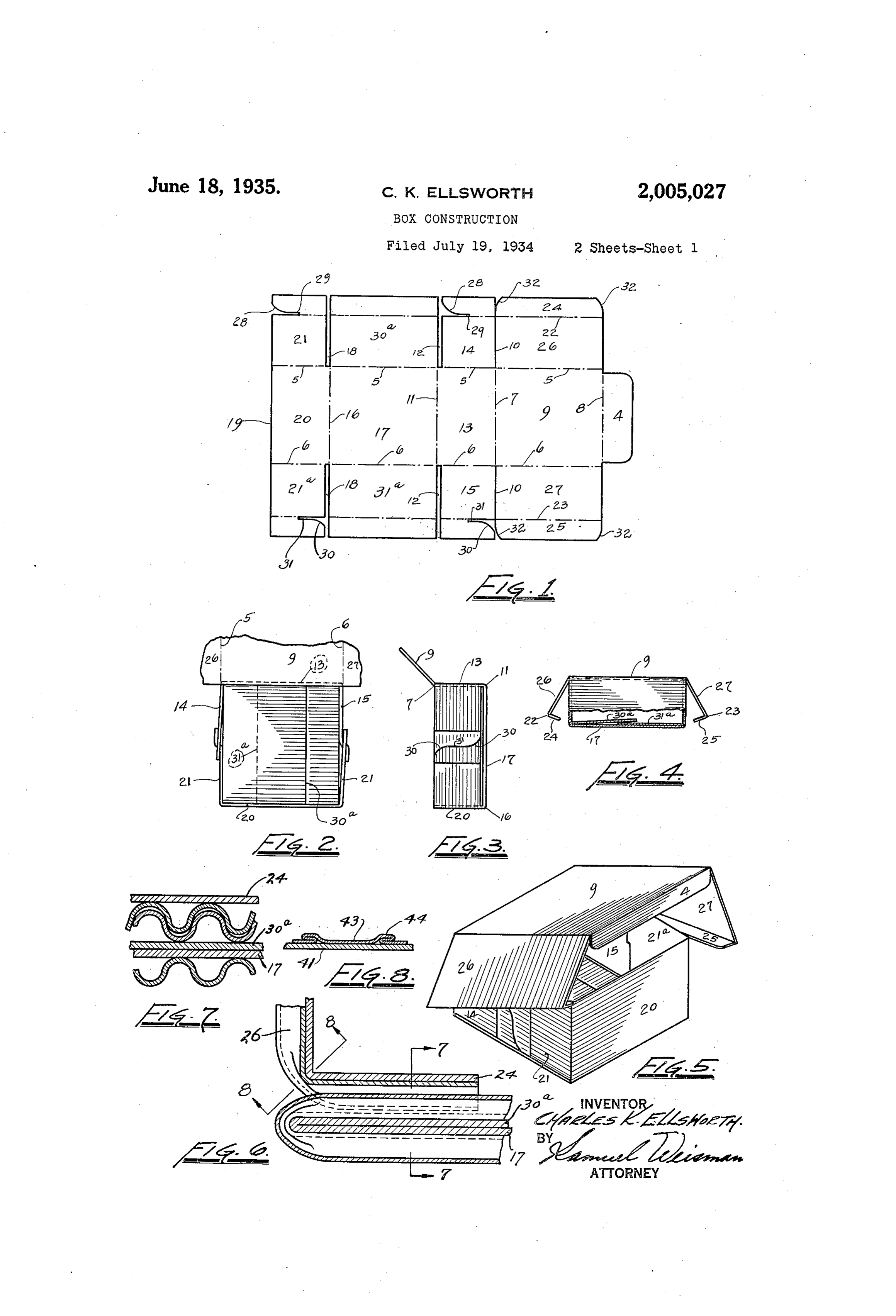
The present invention pertains to a novel box The flattening of the corrugations is gradual, 5 made of material known as single-face corru increasing with the approach to the Crease line. gated stock. This material consists of a corru Consequently there is a tapering of the corru gated piece on One. Surface of which is Secured a gations towards the crease line, producing an flat or face piece. The stock may consist of any interesting design effect and also reducing the Suitable grade of paper Such as chip or jute in the exposure of the corrugations at the most Sensi O , cheaper grades and kraft or sulphite in the bet tive places, namely the corners or edges. 0. ter and Stronger grades. Finally, single-face corrugated Stock is more Among the objects of the invention is the pro economical than plain flat Stock for a given Vision of a box that ends itself to novel and in strength of box. A single-face corrugated piece. teresting design treatment and one that has of given strength has been found to Weigh ap comparatively great strength and rigidity for a proximately one-half to one-third less than a 5 given weight of stock. plain flat sheet of the same strength. Boxes Heretofore Single-face. COrrugated Stock has are specified for strength, which depends on the been used as padding. The essential novelty of weight, and are priced according to weight. the present invention resides in the use of Such Consequently the reduction in neceSSary Weight 20 material in making boxes, cartons and other con for a given strength, by the use of single-face 20. tainers, With the corrugations On the Outside of corrugated stock, is an important economy. the container. Here the corrugations do not The invention is fully disclosed by Way of ex perform their usual functions of padding and ample in the following description and in the ac cushioning, but the material treated in this way companying drawings in which 25 lends itself to interesting ornamental effects as Figure 1 is a plan view of the blank, showing Well as to certain mechanical uses of the corru the inner Surface thereof;
gations not heretofore realized. Figure 2 is a top plan view of the box in open Among these uses is the interlocking engage condition showing the latches and the overlap ment between a flap on one of the walls of the ping bottom pieces;
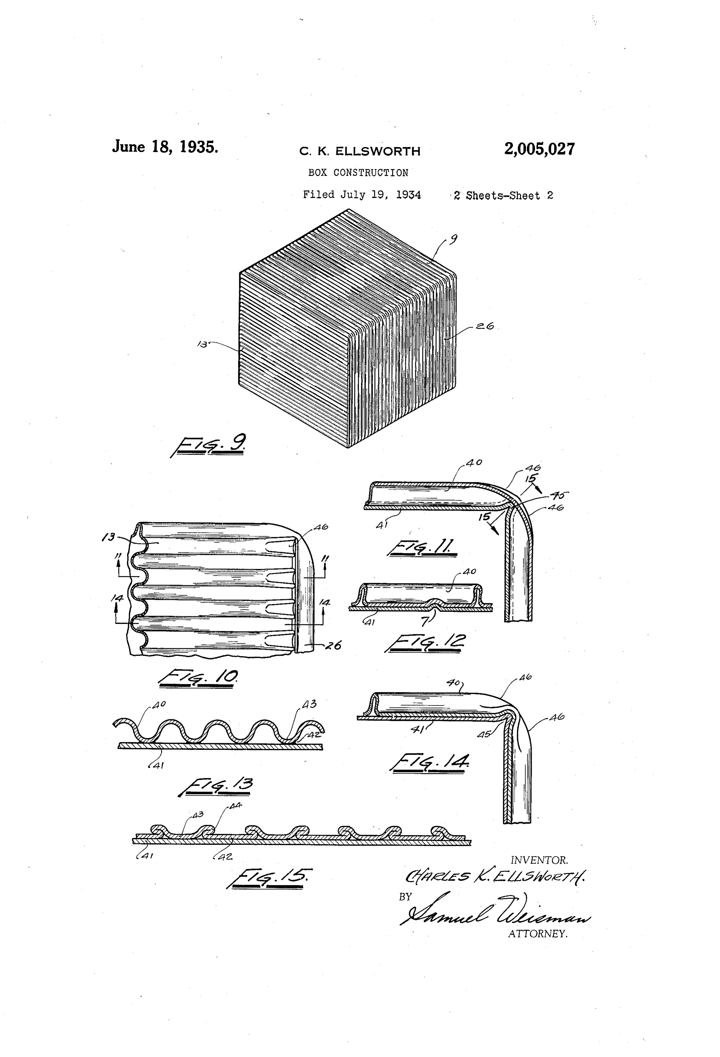
30 box and a tuck folded under from one of the Figure 3 is an end view of Figure 2, showing 30 other walls of the box. The flap and tuck are the latch in elevation; m So positioned that the corrugations of One lie Figure 4 is a front elevation, partly in section, parallel to and face those of the other, where showing the flaps about to be inserted; upon a meshing of the corrugations occurs when Figure 5 is a perspective view of the box with 35 the flap is inserted. The total area of a corru the cover slightly raised; gated Surface is naturally larger than that of a Figure 6 is a detail section of the bottom, show plane Surface Within the same confines. Conse ing the meshing engagement between certain quently there is a correspondingly greater area of corrugated parts; . frictional contact between the flap and the tuck, Figure 7 is a section on the line - of Fig 40 as a result of which the flap is held more securely ure 6; 40 than if it Were flat. Another result of the inter Figure 8 is an enlarged section on the line locking engagement of the corrugated Surfaces 8-8 of Figure 6. showing the flattening of the is that it functions as a brace against side play corrugations by creasing the material with the of the flap, the wall carrying the flap, and in corrugations out Ward;
45 fact the box as a Whole. 45 Figure 9 is a perspective view of the box in
In most boxes formed of a blank of Single-face closed corrugated Stock, there is at least one Score line position;
or crease transversely of the corrugations. The Figure i0 is a detail elevation thereof at One creasing of the material transversely of the cor of the corners 50 rugations brings the corrugated sheet into firm Figure 1 is a Section on the line - - , of contact with the face sheet along the crease Figure 10;
line. Also, the corrugations are somewhat Figure 12 is a cross section of the corrugated Widened where flattened against the crease line, Stock;
with the result that the solid thickness of the Figure 13 is a cross section of the stock at a 55 stock is increased along a Substantial part of the SCOre line;
Page 4
Figure 14 is a section on the line 4-4 of constituting opposite side walls of the box. The Figure 10, and distance between lines 5 and 22 and between lines Figure 15 is a section on the line 5-5 of 6 and 23 is equal to the distance between lines Figure 11. and f , as these three distances represent the Reference to these views will now be made by height or depth of the assembled box. use of like characters which are employed to The Wings 4 and 2 are each notched at 28 designate corresponding parts throughout. near One of the outer corners, the notches ter In Figure 1 is shown a blank of Single-face minating in slits 29 lying in the prolongation of corrugated Stock, this material consisting of a the Score line 22. Both notches 28 face in the O flat sheet. 2 on which is glued or otherwise se Same direction. The distance between each slit, 10 cured a corrugated sheet 3. Both sheets consist 29 and the line 5 is equal to half a side of the of a Suitable grade of paper Such as chip, jute, Square 9 or .
kraft or Sulphite. In like manner, the Wings 5 and 2 are Blank is of Substantially rectangular form, in notched at 39 near one of the outer corners of the present instance, with the exception of a tab each, the notches terminating in slits 3 in the 15 or flap 4 projecting from one of the edges. For prolongation of the score line, 23. The notches convenience of description, it may be assumed 38 face in the opposite direction of the notches 28. that the tab. 4 is located at one of the narrower Again, the distance between each slit 3 and the edges of the blank, representing the Width, and line 6. is equal to half a side of the square 9 or 7. 20 that the other edges represent the length of the Outward of the lines 5 and 6 and between the 20 blank. It will be understood, however, that this slots 2 and 8 there remain pieces 308 and 3 a. relation may be altered in laying out a blank for In aSSenbling the box, these pieces are folded a box having a top and bottom that are not Over on the bottom So that the corrugations of Square. In the present instance, the top and bot these pieces are outward or exposed. In this 25 tom are Square, as will presently be shown. position they reinforce the bottom. If desired, 25 From the end of the tab 4, two score lines 5 and these pieces may be cut off on lines parallel to 6 are drawn lengthwise of the blank and parallel the lines 5 and 6 to such an extent that their to the longitudinal edges. A score line is drawn free edges abut each other on the bottom f, acroSS the sheet parallel to the edge 8 carrying thereby covering the bottom without overlapping, 30 the tab 4, and spaced from this edge a distance but if overlapping is objectionable, the excess 30 equal to the length of the tab. 4. The lines 5, 6 material is preferably used for internal bracing. and 7 and the edge 8 define a Square 9 designed The blank is then creased on lines and 6, to constitute the top of the box. The blank is bringing the end walls 3 and 20 in planes per cut at 0 along the line 7 from the longitudinal pendicular to that of the bottom 7. The wings : edges of the bank as far as the corners of the 5 and 2 are now swung inward on the line 6 35 Square 9. and are interlocked at their notches 30 and slits Another score line f is drawn across the sheet 3. Thus joined, the wings are exactly coexten and is Spaced from the line T a distance repre Sive. With One side of the square because of the Senting the height or depth of the box. Slots 2 relation of dimensions previously described. Sim 40. are cut in the blank along this line from the lon ilarly, the wings 4 and 2 are turned inward on 40 gitudinal edges in Ward to the Score lines 5 and 6 the line 5 and interlocked at the notches 28 and respectively. The area defined by the lines 5, 6 Slits 29. s and 7 and is a rectangle designed to constitute Another crease is now taken along the line 7, an end 3 of the box. Outward of the lines 5 and bringing the top. 9 directly over the bottom 7. 45 6, Wings 4 and 5 are formed respectively be The tab. 4 is inserted against the inner face of end 45 tween each cut 0 and slot 2 for a purpose which Wall 20 and along the edge 9. The side walls 26 Will presently be described. and 27 are now turned downward on the lines 5 Another score line 6 across the blank is lo and 6, whereby these walls cover the interlocked cated at a distance from the line equal to a wings 4 and 2. Only the flaps 24 and 25 now. 50 side of the square 9. The lines and 6 form remain exposed, and these, after being folded on 50 with the lines 5 and 6 another square 7, equai lines 22 and 23 respectively, are inserted beneath to the Square 9 and constituting the bottom of the wings in the spaces provided by slots 2 and the box. The blank is again slotted along the f8, whereby the flaps come into surface engage line 6 from the outer end thereof inward as far ment with the folds 30a and 3 a. as the Corners of the square T. as indicated by the The blank is laid out for scoring and folding in 55 numeral 8. Such a way that the corrugations run perpendicu Between the line 6 and the remaining short lar to the line 5 on which the folds 30a and 3 a. edge 8 of the blank, there remains a strip equal are creased. Where the corrugations run in this in width to the end wall 3. The lines 5, 6 and manner from one crease line to the next, they 60, 6 define in this strip a rectangle 2.0 equal to. serve as an effective brace for the Wall on which 60 the rectangle 3 and constituting the opposite they lie. . . . end Wall of the box. Outward of the lines 5 and 6. Also, throughout the creasing operations, the and between the slots. 8 and edge 9 are formed corrugations are caused to remain on the outside. wings 2 and 2 at the ends of rectangle 20 for Therefore, in inserting the flaps 24 and 25, the 65 a purpose which will presently appear. In cases corrugated surface of each engages the corrugated where the box is so dimensioned that the wings surface of the corresponding fold 30a or 3a, with do not meet, there is no latching, and the box the corrugations on the folds parallel to those on is held together by the engagement of the wings the flaps, so that they mesh or interlock as shown with top 9 and flaps 24, 25. more clearly on Figures 6 and 7. This form of The blank is again scored lengthwise at .22 and engagement results in a large total area of fric 23 between the edge 8 and line is a comparatively. tional Surface contact relatively to the over-all Short distance from the longitudinal edges of the area of the pieces. The flaps are, therefore, held blank to form a pair of flaps 24 and 25. The lines, With more than usual firmness in the inserted 22 and 23 co-operate with the lines 5 and 6 re position, and this is true although there may be Spectively to form a pair of rectangles 26 and 27 more or less outward bulge of the bottom fi along 75
Page 5
the lines 5 and 6, as the extent of the bulge dimin tuck and with its corrugations parallel to and in ishes in receding for the edgeS. nesh. With those of the tuck. Further, the meshing of the corrugations re 2. In a box, a sheet of single-face corrugated sists. Side play of the flaps 24 and 25, thereby re stock creased to present the corrugations out 5 taining also the side walls 26 and 2 and main ward, a tuck under one of the sides of the box 5 taining the desired shape of the whole box. In with its corrugated Side facing inward of the box, this connection it is to be noted that the ends of a flap formed on another wall of the box and po the fiaps 24 and 25 alone are not sufficient to brace Sitioned to be inserted in Surface engagement with the box, first because they are shortened by said tuck and With its corrugations parallel to and () rounding the cornei's of the flaps at 32 to facili in mesh with those of the tuck, and means for tate insertion, and Second because the Stock is maintaining said tuck and flap in Surface engage Weak at the edges and breaks doW. inent With each other.
Another property of the interlocking engage 3. In a box, a Sheet of Single-face corrugated ment of the corrugations is the Sealing effect pro Stock creased to present the corrugations Out duced thereby. The sealing effect, which is pro ward, a tuck under one of the sides of the box portional to the increased area of contact aS al with its corrugated side facing inward of the box, ready set forth, is usual in insulating the contents a flap formed on another Wall of the box and of the box from outside air and heat, especially positioned to be inserted in Surface engagement when the box contains unwrapped food, Such as With Said tuck and with its corrugations parallel cookies, or bottles of a chilled beverage. to and in nesh. With those of the tuck, and a leaf 20 Another important feature of the invention is integral With said sheet and SWigable On an axis the formation that occurs by the distortion of the angular to that of the tuck, the fiap being in Sert corrugations where the blank is creased trans able between said leaf and said flap, whereby the versely of the corrugations, with the corrugations leaf tends to maintain the tuck and flap in Sur 25 on the cutside, as shown in Figures 8 to 15. This face engagement. With each other, formation is best illustrated in Figures 4 and 5, 4. A QX coiliprising a blank having tWO Score showing the formation on a magnified Scale. The lines in one direction and three Score lines in the corrugated sheet 48 is secured to the face sheet perpendicular direction, thereby forming four 4 along parallel bands 42 which constitute the rectangles between the first two lines, two alter 30 troughs between the corrugations 43 where the nate rectangles constituting the top and botton sheet it is spaced from the sheet 4. On forning respectively and the intervening recta.Engles con a crease in the manner described along a Score stituting end walls, the blank being sit outward ine shown in Figure 12, the Sheet 43 is placed froin the first two lines along the second named under tension in the direction of the corrugations, three Score lines, thereby forming Wings at the 3 5 flattening the corrugations into contact With the ends Of the end Walls and lateral pieces at the 35 crease line along areas of contact at least as ends of the top and bottom, those at the botton wide as the spaces between the adhesion bands 42. being foided in Wardly and lying flat on the bot Thus, the solid, uninterrupted thickness of the tom, and those at the top constituting side walls, stock is increased by the thickness of the sheet means for interlocking said Wings along the side 4 not only at the bands, but also in the Spaces Walls, and flaps formed. On Said Side. Walls re 40 between the bands, thereby reinforcing the box Spectively on lines parallel to the first two score where added strength is needed, namely at the lines and inserted beneath Said Wings and into crease. In fact, the corrugations in fattening Surface contact with the lateral pieces overlying overlap the secured areas to form ribs 44 of still the bottom.
greater thickness and strength acroSS the crease 5. A box comprising a blank having two score 45 at intervals. lines in One direction and three Score lines in the Considering the distortion of the corrugations perpendicular direction, thereby forming four in the lengthwise direction it will be seen that the rectangles between the first two lines, two alter flattening is gradual, reaching its maximum at nate rectangles constituting the top and bottom the crease line 45. In other words, there is a respectively and the intervening rectangles coin 50 taper 46 of the material on adjacent p8rpendicul Stituting end Walls, the blank being sit outward lar walls of the box and towards the crease line, frcin the first two lines along the Second named as may be seen in Figures 10 and 11. This forma three SCOI'e lines, thereby forming wings at the tion reduces the protrusion and exposure of the ends of the end Walls and lateral pieces at the 5 5 corrugations at the creases where the wear on the ends of the top and botton, those at the bottom 55 Outer Surface of the box is the greatest, and as a being folded inwardly and lying flat on the bot result of this formation the sheet 40 remains in tOn and those at the top constituting side walls, tact at the crease notwithstanding Severe Wear means for interlocking said wings along the side in this area. Walls, and flap3 formed on Said Side Wallis re 60 The invention is not limited to paper Stock, as Spectively On lines parallel to the first two score 60 other fabric and flexible materials may be corru lineS and inserted beneath said Wings and into gated and used in the manner described. Al Surface contact with the lateral pieces overlying though a specific embodiment of the invention the botton, the Wings being enclosed by said side has been illustrated and described, it Will be un Wals.
derstood that various alterations in the details of 6. A box COrprising a blank having two score. 65 construction may be made without departing lines in One direction and three Score lines in the from the scope of the invention, as indicated by perpendicular direction, thereby forming four the appended claims. rectangles between the first two lines, two alter What I claim is: nate rectangles constituting the top and bottom 1. In a box, a sheet of single-face corrugated respectively and the intervening rectangles con 70 stock creased to present the corrugations out Stituting end Walls, the blank being sit OutWard Ward, a tuck under one of the sides of the box with from the first two lies along the Second named its corrugated Side facing inward of the box, a fiap three score lines, thereby forming wings at the formed on another Wall of the box and positioned ends of the end Walls and lateral pieces at the ends to be inserted in Surface engagement With Said of the top and bottom, those at the bottom being
Page 6
folded inwardly and lying flat on the bottom to mesh and interlock with those on the lateral and those at the top constituting side Walls, pieces Overlying the bottom. - means for interlocking said Wings along the side 8. A box made of single-face corrugated stock, Walls, and flaps formed on said side walls re Said Stock consisting of a flat sheet and a corru Spectively on lines parallel to the first two score gated sheet secured thereto along spaced bands 5 lines and inserted beneath said Wings and into at the bases of the corrugations, the crests of the Surface, contact with the lateral pieces overlying corrugations being spaced from said flat sheet, the botton, said blanks being corrugated on the Said box having at least one crease transversely OutSide, the corrugations running transversely of of the corrugations, the corrugations being ex () the first two Score lines, the corrugations on the posed on the outside of the angle thus formed, the O flaps being adapted to mesh and interlock with Crests of the corrugations being flattened into those Cn the lateral pieces, overlying the bottom. firm engagement with the flat sheet at said crease 7. A box comprising a blank having two score and between Said bands.
lines in One direction and three Score lines in the 9. A box made of single-face corrugated stock, perpendicular direction, thereby forming four Said stock consisting of a flat sheet and a corru rectangles between the first two lines, two al gated sheet. Secured thereto along spaced bands ternate rectangles constituting the top and bot at the bases of the corrugations, the crests of tom respectively and the intervening rectangles the corregations being spaced from said flat sheet, constituting end walls, the blank being slit out Said box having at least one crease transversely 2) Ward from the first two lines along the second of the corrugations, the corrugations being ex 20 named three score lines, thereby forming wings posed on the outside of the angle thus formed, at the ends of the end Walls and lateral pieces at the crests of the corrugations being flattened into the ends of the top and botton, those at the bot firm engagement with the flat sheet at said crease tom being foided inwardly and lying fiat on the aid between said bands, the flattened corruga
bottom and those at the top constituting side tions 10.
overlapping said bands to form ribs.
A box made of single-face corrugated stock,
walls, means for interlocking said wings along Said Stock consisting of a flat sheet and a corrui the Side Walls, and flaps formed on said Side Was gated sheet Secured thereto along spaced bands at respectively on lines parallel to the first two the bases of the corrugations, said sheet being score lines and inserted beneath said wings and creased tiansversely of the corrugations, the cor into surface contact with the lateral pieces over rugations gradually diminishing in height towards lying the bottom, a corrugated sheet covering the the crease from points spaced from said crease, Outer Surface of the blank or box, the corruga and being flattened into engagement with the flat tions running transversely of the first two score sheet at the crease.
lines, the corrugations. On the flaps being adapted CHARLES K. ELLSWORTH.
Provenance
- Collection
- Cited prior art
- Original PDF
- patentimages.storage.googleapis.com →
- Filed
- 1934-07-19
- Pages
- 6
- Method
- pdftotext (the PDF's own text layer) + pdftoppm 300dpi page scans
- Source
- Google Patents bibliographic record
- Granted
- 1935-06-18
- Inventors
- Charles K Ellsworth
- Transcribed from
- patentimages.storage.googleapis.com →