patent · US20170268465A1
Voltage Calculator and Generator for On-Board Diagnostic System and Method of Using the Same
21 September 2017
Page 1 — bibliographic record
HUNHAM ANAU DITUGI EINUTRIKUTALEONTHE
( 19) United States (12) Agrahar
PatentetApplication
(43) Pub. Date : Sep . 21, 2017 (54 ) VOLTAGE CALCULATOR AND GENERATOR Publication Classification FOR ON -BOARD DIAGNOSTIC SYSTEM (51) Int. CI.
AND METHOD OF USING THE SAME F02M 25 / 12 ( 2006 . 01) (71) Applicant: ImageStatistics, Inc., Philadelphia, PA F02D 41/26 ( 2006 .01 ) (US) F02D 41/ 20 ( 2006 .01)
( 72 ) Inventors: Vikram Agrahar, Philadelphia , PA (52 ) CPC
(US ); Joseph Gaetz, Philadelphia , PA ....... ... F02M 25 / 12 (2013.01) ; F02D 41/ 28 (US ); Lalit K . Aggarwal, Philadelphia , (2013 .01); F02D 41/ 263 (2013 .01) ; F02D PA (US ) 41/20 ( 2013 .01); F02D 2041/ 281 (2013. 01 ); (21) Appl. No.: 15/509,686 F02D 2041/ 2013 ( 2013.01)
(86 ) PCT No.: PCT/US15 /53482 (57 ) ABSTRACT
(2 ) Date : Mar. 8, 2017 A system and method are described for providing hydrogen Related U .S. Application Data gas to an internal combustion engine based , in part, on selected data retrieved from a vehicle interface to reduce (60) Provisional application No. 62/058 ,879, filed on Oct. particulate and harmfulmatter from emissions and improve 2 , 2014 . efficiency .
Page 2
Drawing sheet — no readable text.
Page 3
Drawing sheet — no readable text.
Page 4
Drawing sheet — no readable text.
Page 5
Patent Application Publication Sep . 21 , 2017 Sheet 4 of 10 US 2017 /0268465 A1
Check Vehicle Interface Connectivity (4010 )
N. Set System to Sleep and Wait for
Interface Connected ? ( 4020 ) Delay (4030 )
Check System Devices (4040 )
Acquire Selected Interface Data (4050 )
Process Selected Interface Data ( 4060 ) Data from PWM
Processor and /or
Main Processor
Process Feedback Select Value from Look Up Table (LUT) Saved to On Board Data and Adjust (4070 ) and Produce Processor Signal Storage (4080 )
Transmit Processor Signal to System Powered On
Pulse Width Modulation (PWM ) (4090 )
Check System Sensors
Processor (4150 )
PWM Processor Checks Voltage to be Generated (4160 ) - System Wirelessly
Connected to to Provide Feedback Central Servers ? Data (4260) (4100) PWM Processor Prepares a Pulse
Transmit Saved
Data to Central
PWM Processor Transmits Pulse Servers ( optionally Stream to Power Driver (4180 ) deleted from
Power Source
Provides Power to Power Driver Provides an
Power Driver (4250 ) Applied Voltage (4190 ) Central Servers Provide a
Power Driver Output
Parameters are
Measured (4240 )
Applied Voltage is Filtered to
Provide Filtered Applied Voltage
- Modified LUT and /or Software
Process Repeated DC Voltage Transmitted to Halt System and (4230 ) Hydrogen Source (4210 ) Update LUT and /or Software
Hydrogen Source Provides
Hydrogen to Engine ( 4220 ) | Resume System
Page 6
Patent Application Publication Sep . 21 , 2017 Sheet 5 of 10 US 2017 /0268465 A1 - - - - - - - - - - - - - 1
: 5020 -
C er u VUSLIKE -
KIA -
Ohio
Joviainen
rái
1W -
yeni irei
T943923 40 pig
YWO
XO 5065
CHER
- . -
- ina ?otva 95€.8 TE S & K
- -
- - intr
RAT
- - - -
Yo WWW -
- -
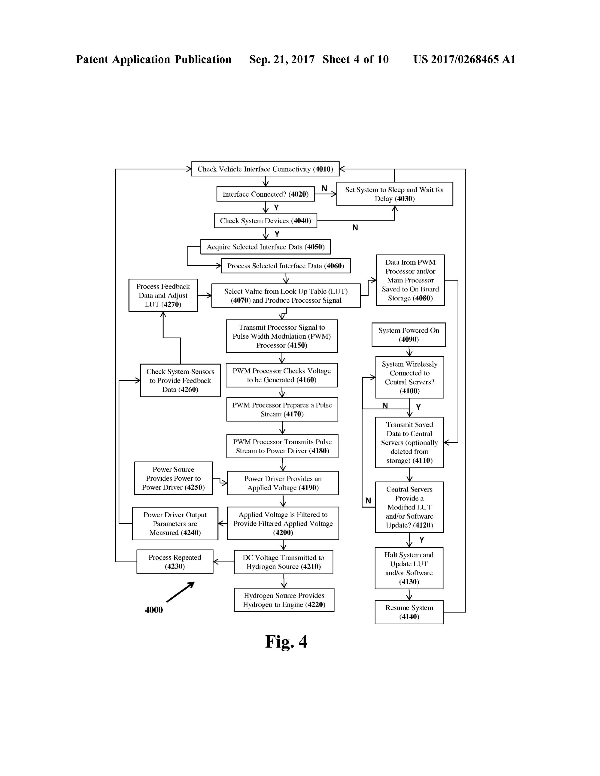
Frisir i - -
- - -
- - - rrr
EX 67
? +
Fig
rror
VANYvw rienvgawm
LUSEL
. -
www
Releases _7-2.r r * - --
* .
- *
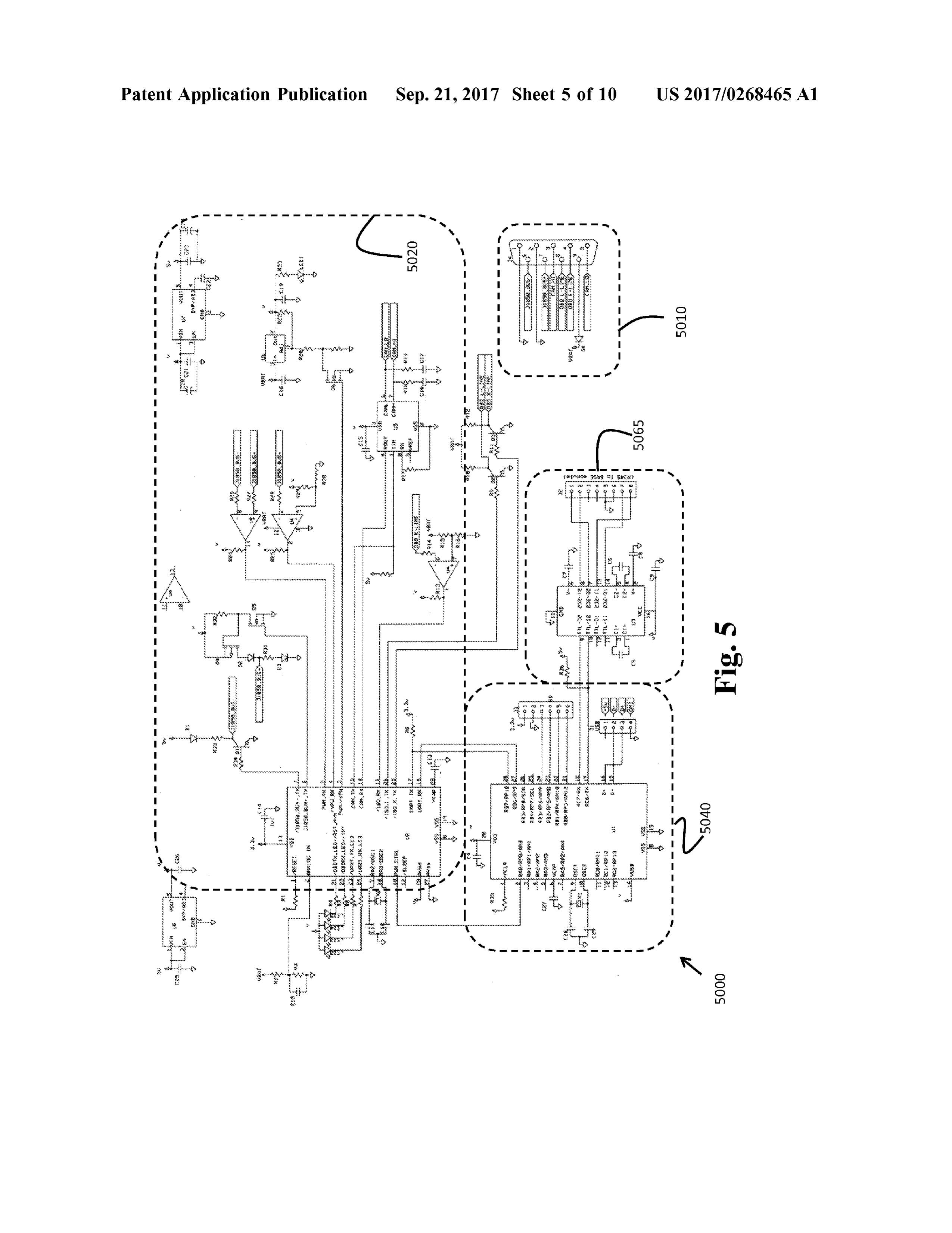
CFxWVTI
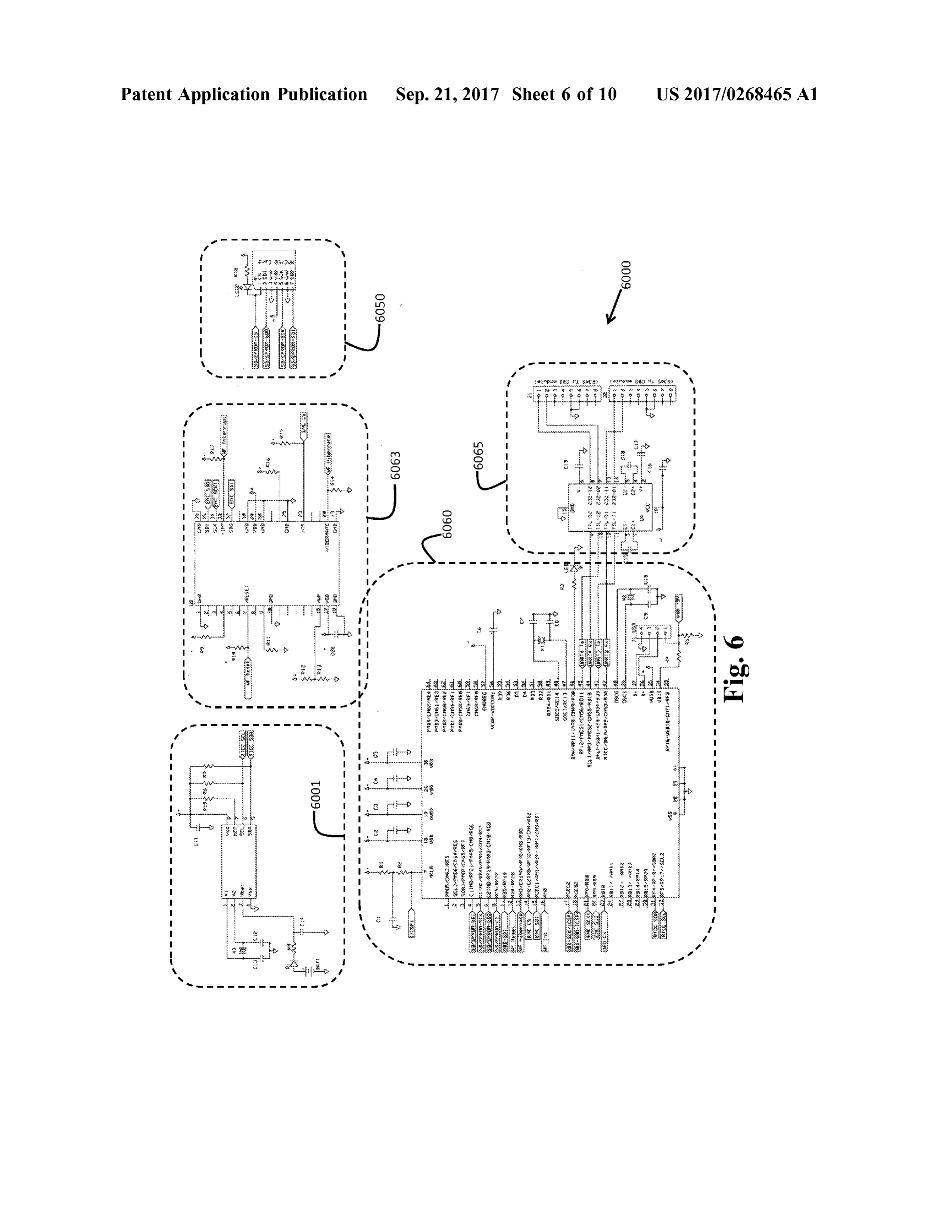
Xord
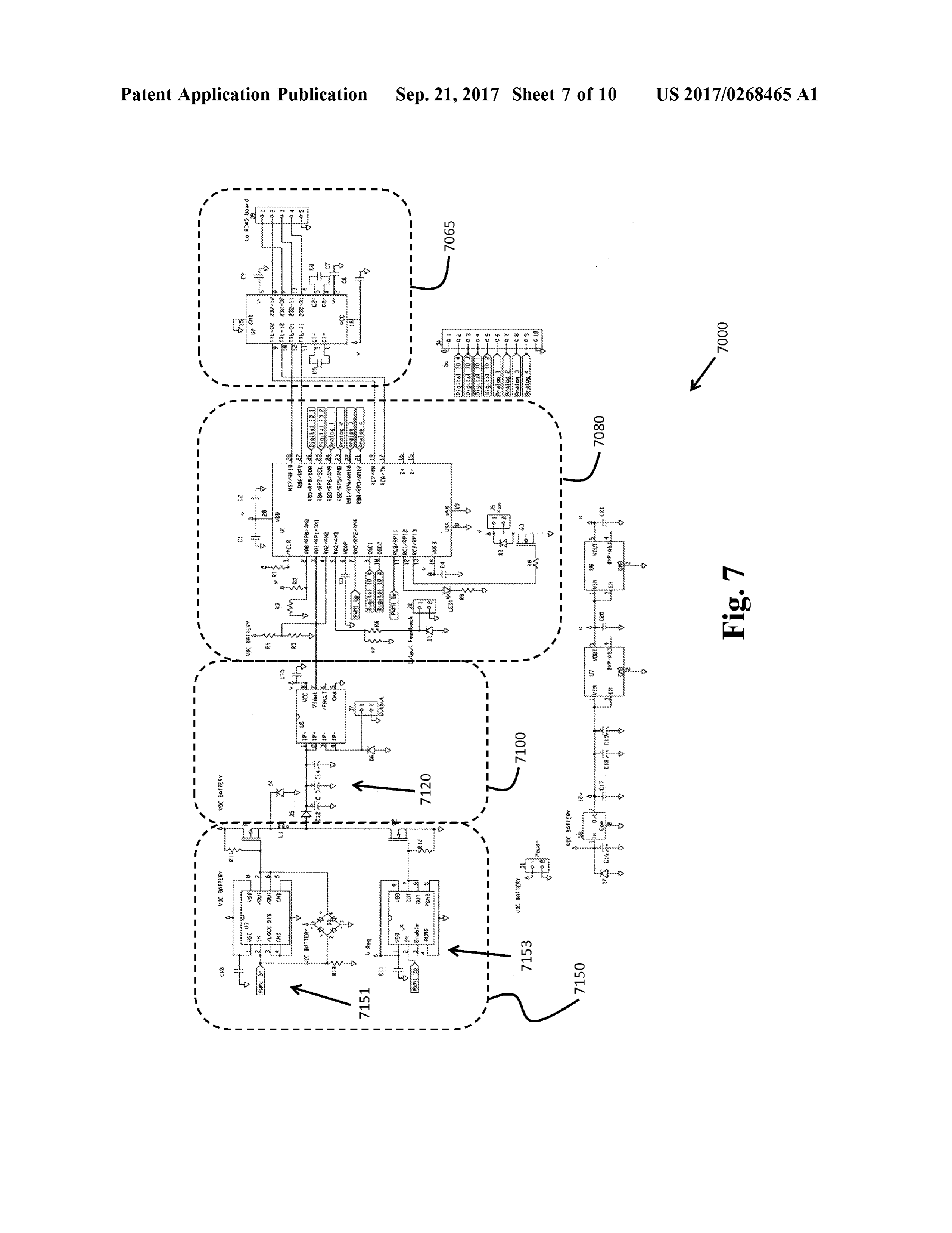
wr ni !
VAR
Lila
* -
- and
Xy 5
Wil
eambiwa R
vor ent
NI :
: 268
90 -
mm WRINGAQN
resep
235 W 00s
Community $ prorter
Remix
urt
X!57T 37.6ss .cuso
Tid b
port
Pat oren
Unidos . www
ICA rer63 50 0
Page 7
Patent Application Publication Sep . 21 , 2017 Sheet 6 of 10 US 2017 /0268465 A1
AUDI
WSON
mo -
KIT
Contuie
LLLLLLLLLLLL
I - - --
TV W
Wews
- !
E STI
TKO
lagits 01/
Lepty
proces
LUF QAT
COMZY LI
bin
ZEYyo
- 1
Fig
103 F
. W . W1 .
"193QIPH UKO
1915 E!IlDcEhWu 4(1P3 MAX *
BrUoCwnS 1
nemamente -
ent 56
- ! stimulant 00HV1I9S $
4 0724 -
24 -
Evidél
IT YVYN 474 7380953 X 48
merbenyB&aby 1sin2o5s Crv18 6 21002588 /P1l87o2751486268.
4 -
IT 234 x asolut
Der
. -
Bisher
Iliatev SUI
: W
-Winds 2-13368. 452 96
- - - - - - - - - - -
Page 8
Patent Application Publication Sep . 21 , 2017 Sheet 7 of 10 US 2017 /0268465 A1
Wearing
23 View
t 153 -
EDOPOLE comb
- -
. 1 - - LED
her
Ligita
lm Rien
Q102i al íboom
4 340173826198 64 d9283 YAPMINERL 971
2FREAGPA PIR PIRPozi-Coves| THEAT 3 5278 b10esten .Pidgin
opkulgeni 138690
6 -
worieon
wir you
Fig
ou a 103 -
> .
! 43
Witosi273 MALM 170YAMA -
vermo A
A -
4 a OZIL .itis17
870 Horor
3*417EGY c c Curer13 POBLE
him
XXV
Gas
Ponto eta
213 ing
eine
Page 9
Patent Application Publication Sep . 21 , 2017 Sheet 8 of 10 US 2017 /0268465 A1 wel IP
22 RAHViautCloutFB) Sp wVauwit
FAULTIER
0 18 with &&&& ???? teltrambrand oforeverli
le Ciment
WYT maanpumpa
WeW An
WAVN
0VDCJAT ERY to 13
FBCmotolout
VIXBAT ERY *
Fig
wwwwwwwwwwwww W
mmer
- -
den DIS
LOCK ON
- -
estiguin B
RES
w - - - - - - - -
Page 10
Patent Application Publication Sep .21, 2017 Sheety of 10 US 2017/ 0268465 A1 - - - - - = = = - - - ?S ???
INFINE
? 3 ? ; ; P-HWHM PLAH ??
fun PM
?? ? 4
-S & KEY 8
PANAL
: : :: S? ? If
CSS3 S40- ? ?? ? = VSS ? ???838
? ? 8 ; ?? : ? ? ,
SPA / ? ASR
3. sput? 3PE N? “?4
? ? ; NS/???
??? ???3
Itl l
= *
?TK ??. x } huwuli. . .
= = = = = = - - - - - - - - = = =
were {
AMA
YEE | Summer
Ping 882?es { " iss Tright) ;
www …
Herrerw
REPE
???? retern that
CRYSE:
E - mainwww
is ?? wenPartie htermmmmmmmmm
CHIT
lacker mmmmmmm
STER
?? ? mingt
Fig. 9A
Whitecticathy 333 iminan
type
Page 11
Patent Application Publication Sep .21, 2017 Sheet 10 of 10 US 2017/ 0268465 A1
Acces
EXP vbCr
?? ? Every ?RPG tip" E ":
KKFZR …
3 :
… Sea
??“RY 13 k :; 2e. }
??? ¢¢
? TT - Xi anason m
LIFE
E ?SS r -
?: # S* h
* Laudias
Alt
TFT
LE F
?? ??S-XP = = = = = = = - - - -
6? - - - - - - - -
mmm
- - ???????????????
1 . Simo Myus
? yt
1 -
. gS odio
…it erver
asic
“ - - = =
Fig . 9B
Page 12
US 2017 /0268465 A1 Sep . 21, 2017
VOLTAGE CALCULATOR AND GENERATOR PWM processor may be configured to provide a pulse FOR ON -BOARD DIAGNOSTIC SYSTEM stream based upon the processor signal. The pulse stream AND METHOD OF USING THE SAME may include a pulse stream time period and a pulse width . Indeed , the main processor may transmit processed data to
CROSS -REFERENCE TO RELATED a PWM processor located elsewhere such as in a vehicle 's APPLICATIONS trunk , engine compartment, or another selected location via 10001] This international application claims the benefit of a communication bus or wireless method . The main proces U . S . Provisional Application No . 62/058 ,879, filed Oct. 2 , sor may also receive data from the PWM processor regard 2014 , the entirety of which is incorporated herein by refer ing a hydrogen source ( e . g ., an electrolyzer ) such as, but not ence . limited to , actual voltage delivered , current rate , gassing rate , temperature , unit temperature , and environment tem
FIELD OF THE INVENTION perature, for example . The main processor may recalibrate the desired output voltage (i. e ., applied voltage ) to adjust for [0002] The present invention relates generally to a system greater system efficiency and lower particulate emissions. and method for providing hydrogen gas to an internal 10008 ] The main processor may transmit data for statisti combustion engine and more particularly , but not exclu sively , to a system and method that utilizes data from a cal logging to peripheral circuit boards that handle data vehicle ' s or engine 's interface device or an external data logging and external communications ( e . g ., communications source to optimize the amount of hydrogen to an internal circuitry ). The main processor may receive data from the combustion engine to reduce particulate and other harmful communications circuitry . The received data may be matter from emissions and improve engine efficiency. obtained from a research facility ( e . g ., a central server ) and may include an updated LUT and other formulas that may
BACKGROUND OF THE INVENTION enhance system performance. The main processor may also get data received from a communications board containing [0003 ] Combustion engines burn fuel to provide motion . system software updates .
In the process of burning fuel, engines produce exhaust products that are environmentally harmful. One reason for [0009] The system of the invention may also include a the production of harmful exhaust products lies in incom power driver in communication with the main processor and plete combustion of the fuel within the engine . For example , a power source , with the power driver configured to receive combustion engines produce particulate matter emissions the pulse stream from the PWM processor and increase or that may, when not controlled or mediated , cause health decrease the magnitude of a power source voltage to provide hazards. an applied voltage to a hydrogen source . [0004 ] Attempts have been made to reduce particulate [0010 ) Furthermore, in the system of the invention , at least matter, including: performing routine preventative mainte one of the main processor and the PWM processor may be nance of engines to minimize emissions; installing aftermar configured to receive feedback data from a sensor after the ket or retrofit engine exhaust filters ; installing cleaner burn provision of an applied voltage to dynamically adjust at least ing engines ; installing aftermarket or retrofit oxidation one of the processor signal and the pulse stream during catalysts ; and/ or using special fuels or fuel additives . How operation of the system .
ever, these attempts have not provided a satisfactory solution to the removal of particulate matter and other harmful [0011 ] In another aspect, the invention includes a method exhaust products from combustion exhaust. for providing hydrogen gas to an internal combustion [0005 ] The present invention fills a need in the field by engine. The method may include the step of acquiring disclosing systems and methods for providing controlled selected data from a vehicle having an internal combustion amounts of hydrogen to internal combustion engines to engine .
improve combustion and thereby reduce the production of [0012 ] The method may further include processing the harmful exhaust products . selected data and comparing the selected data to a look up table to generate a processor signal based on the selected
SUMMARY OF THE INVENTION data . Themethod may also include producing a pulse stream [0006 ] In a first aspect, the present invention includes a based on the processor signal, with the pulse stream includ system for providing hydrogen gas to an internal combustion ing a pulse stream time period and a pulse width . engine . The system may be configured to communicate with [0013 ] The method of the invention may include provid a hydrogen source that provides hydrogen gas to the internal ing a power source voltage to a power driver and changing combustion engine in an amount proportional to an applied the magnitude of the power source voltage based on the voltage. The system may include a main processor config pulse stream to provide an applied voltage , wherein chang ured to receive selected data from at least one of a vehicle ing the magnitude of the power source voltage includes or engine interface device and an external data source where increasing or decreasing the magnitude of the power source the main processor may be configured to generate and voltage . The method may also include providing the applied transmit a processor signal based on the selected data . For voltage to a hydrogen source to produce an amount of example , the main processor may compute a desired voltage to be delivered to an electrolyzer based on a look - up table hydrogen gas proportional to the applied voltage . (LUT) and data obtained from a vehicle 's on -board diag [0014 ] Moreover, the method may include receiving feed nostic (OBD ) device or sensors . back data from a sensor, after providing the applied voltage [0007] The system may also include a pulse width modu to the hydrogen source, and dynamically adjusting at least lation (PWM ) processor in communication with the main one of the processor signal and pulse stream based on the processor for receiving the processor signal , where the feedback data .
Page 13
US 2017 /0268465 A1 Sep . 21, 2017
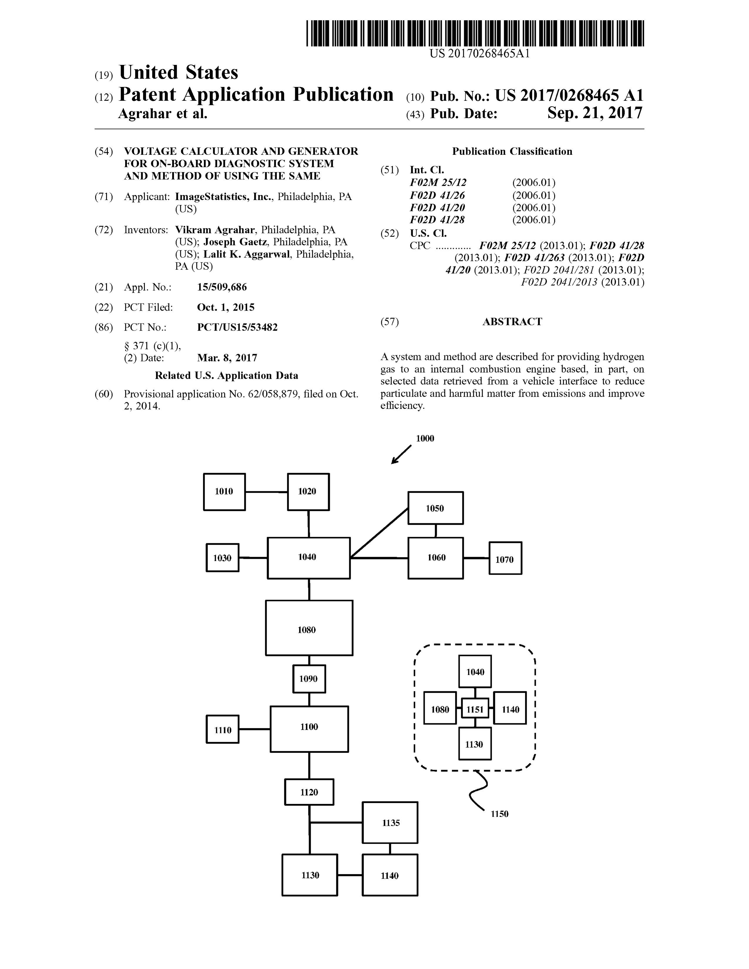
BRIEF DESCRIPTION OF THE DRAWINGS 754 ; 8 ,454,808; 8,499,722 ; and 8 ,757, 107 ; each ofwhich is incorporated by reference herein . In the function of such [0015 ] The foregoing summary and the following detailed devices , hydrogen gas may be injected into the air intake of description of the exemplary embodiments of the present the engine to improve combustion . However, there is a need invention may be further understood when read in conjunc in the field to improve the efficiency of such devices by tion with the appended drawings, where like elements are providing an electronic controller and system that can pre numbered alike throughout, in which : cisely provide selected amounts of hydrogen to the engine to [0016 ] FIG . 1 schematically illustrates a system of the maximize combustion ( e . g ., reduce particulate matter ) and invention that includes a power driver and a hydrogen ensure the efficiency of the system . The present invention source that may be an electrolyzer hydrogen generator. meets those needs .
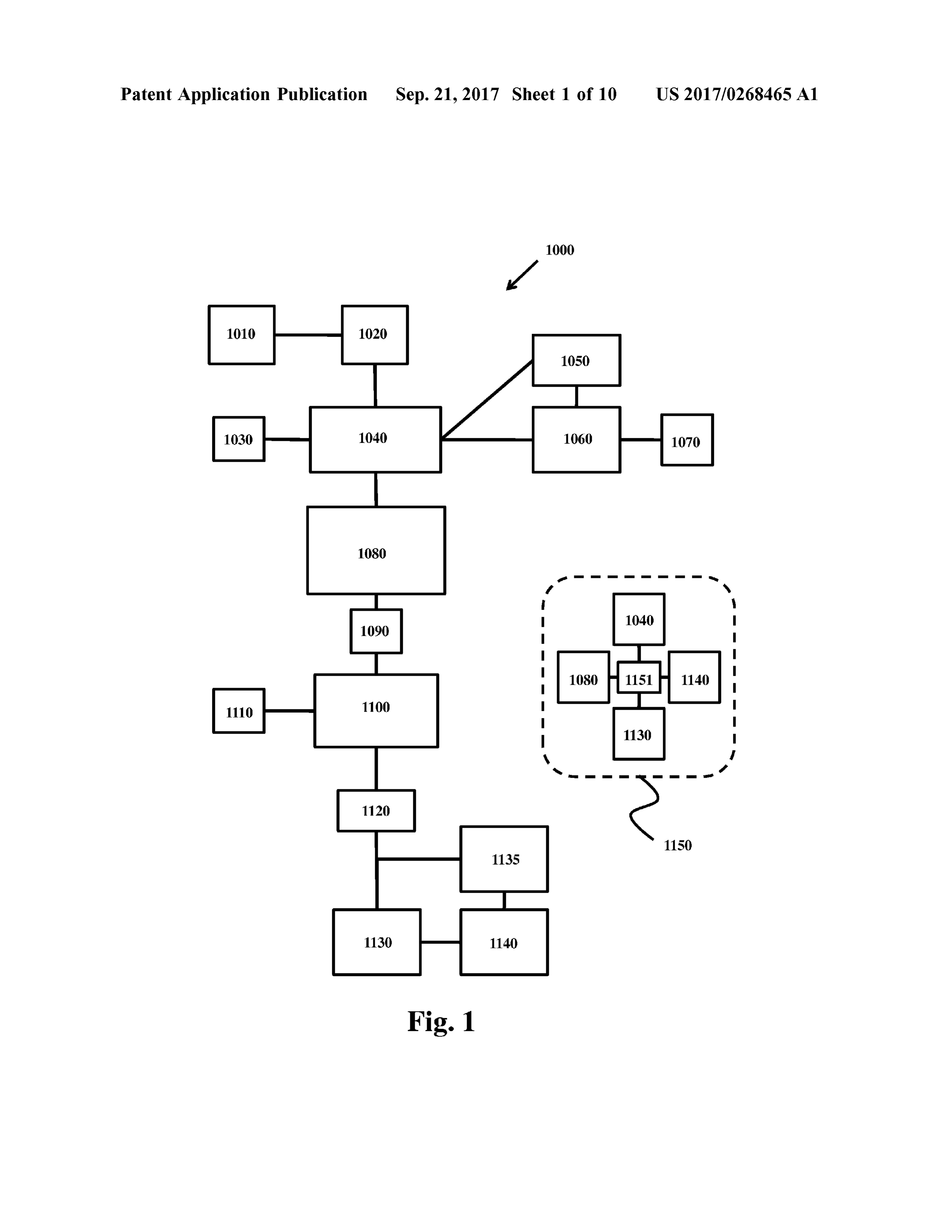
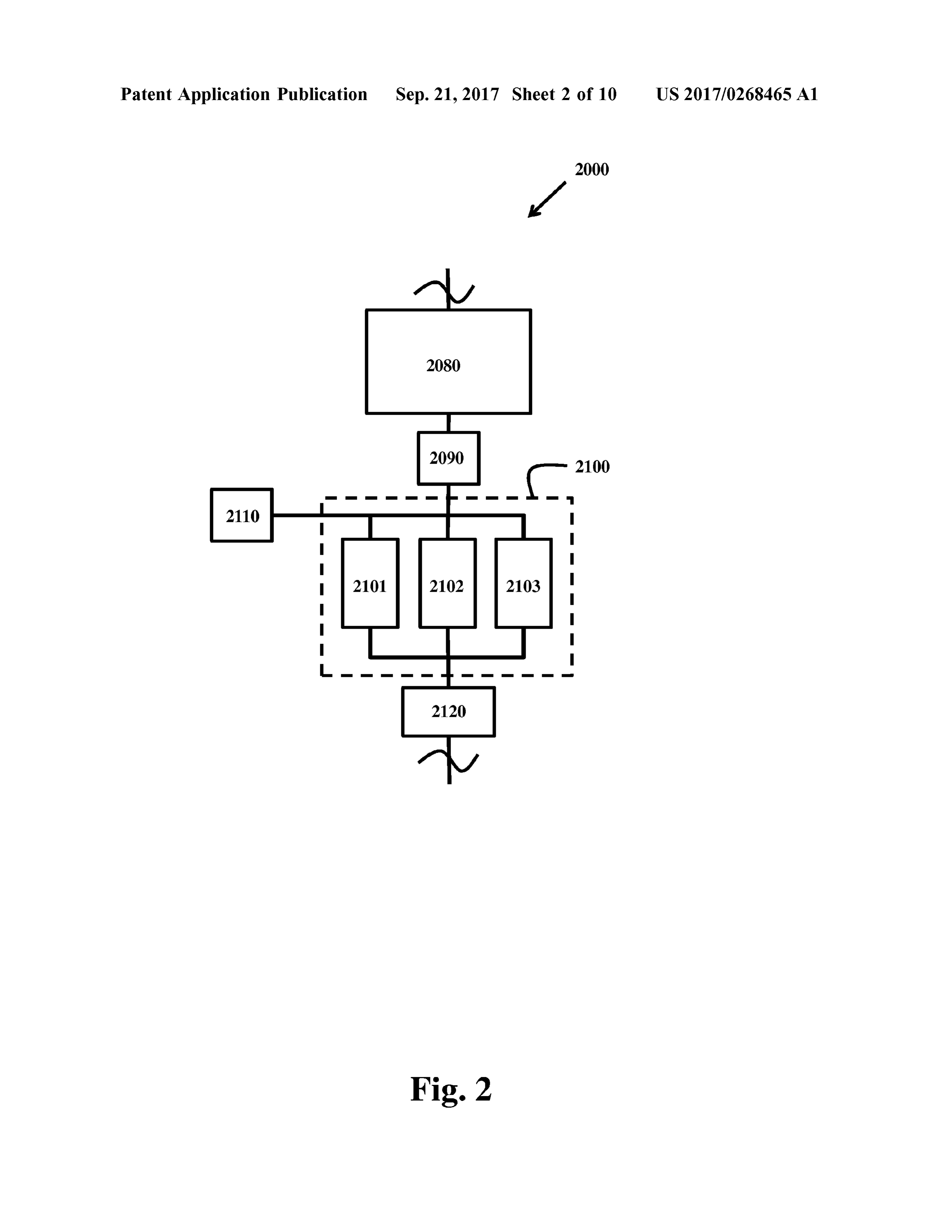
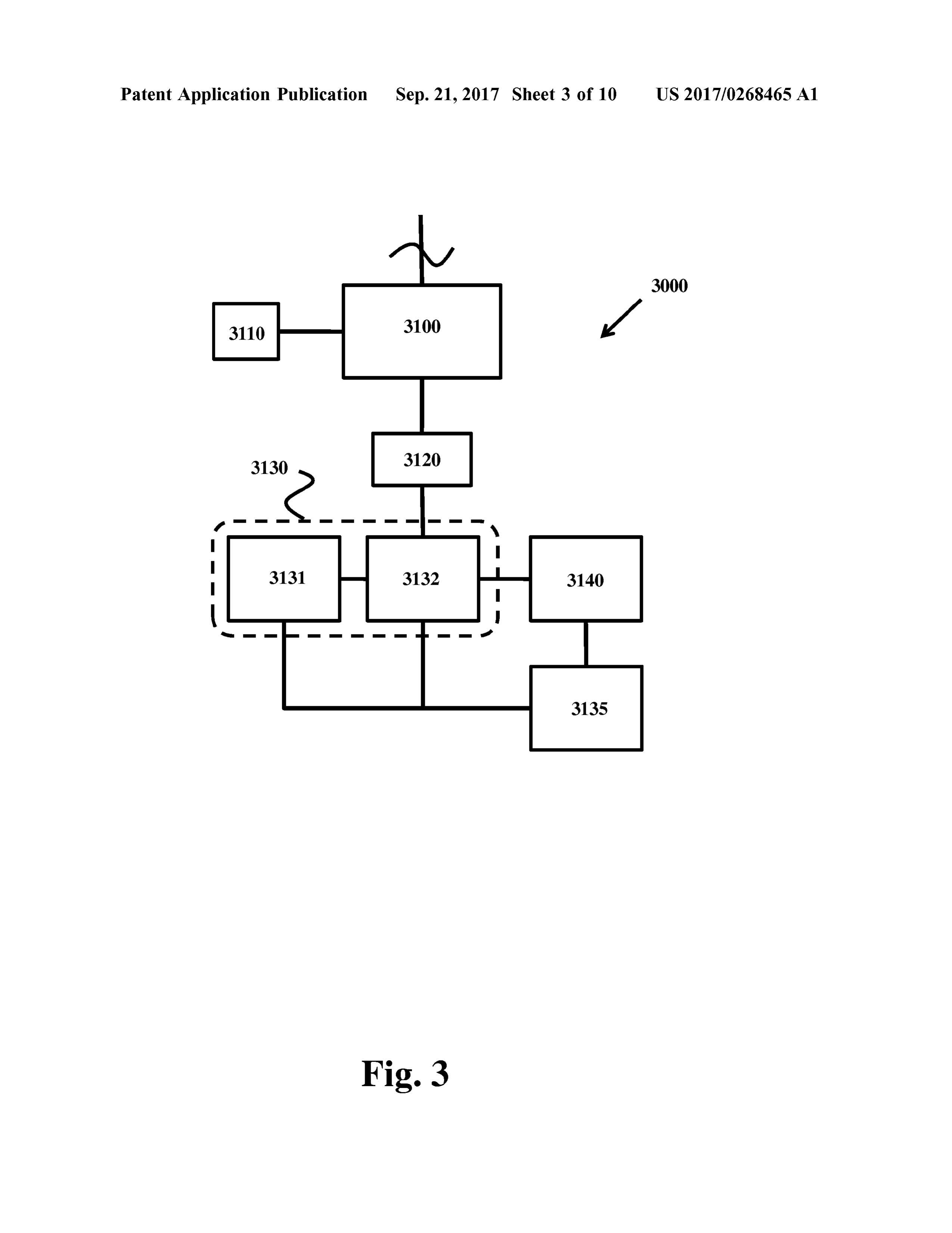
[ 00171. FIG . 2 schematically illustrates a system of the invention having a multi - stage power driver system with a [0027 ] A system of the invention may be connected to a plurality of buck , boost, or buck -boost drivers , depending vehicle or an engine to collect data regarding various upon the design of the system and the voltage provided by parameters such as speed , revolutions per minute (RPM ), or engine load , through various sensors and connections, such the driver power source . as through the vehicle 's or engine' s on -board diagnostic [ 0018 ] FIG . 3 schematically illustrates a system of the (OBD ) device or similar vehicle or engine interface device . invention having a contained hydrogen system as the hydro The system of the invention may translate such information gen source, wherein a hydrogen actuator is connected to a to data that is used for controlling a power amplifier that can hydrogen storage tank and the actuator may be opened and energize a load with the appropriate voltage and current to closed to provide a selected amount of hydrogen to a vehicle provide a certain amount of hydrogen gas from a hydrogen engine. source . The system of the invention may, in addition , [0019] FIG . 4 schematically illustrates a method of oper provide real time diagnostic information to an attached ating a system of the invention . computer, allow configurations to be dynamically changed [0020 ] FIG . 5 schematically illustrates an exemplary as needed , and allow recording of data onto an onboard vehicle On- Board Diagnostic (OBD ) decoder module . storage or remote storage into a database through a wireless 10021] FIG . 6 schematically illustrates an exemplary com connection . The stored information may be used for future munication module used in a system of the invention that analysis .
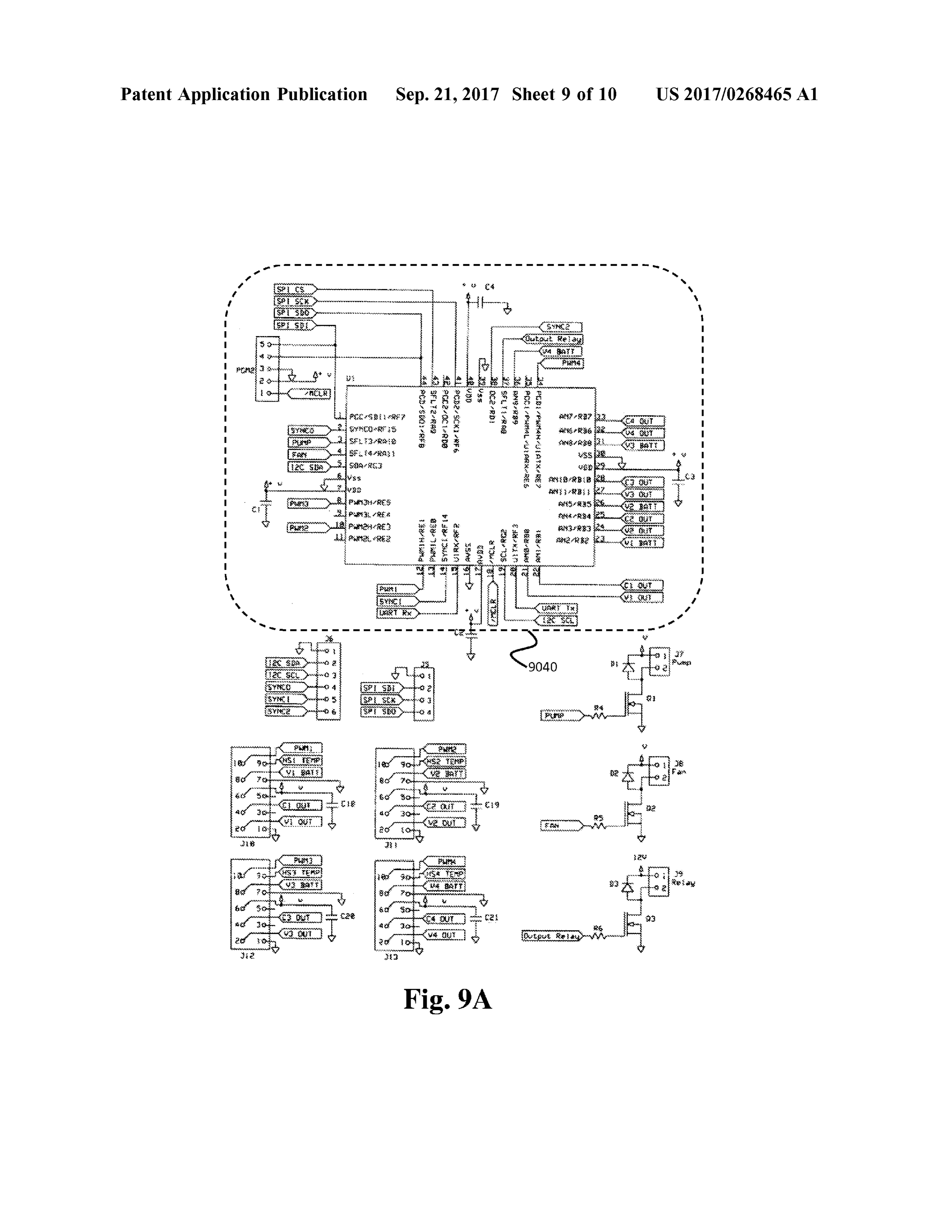
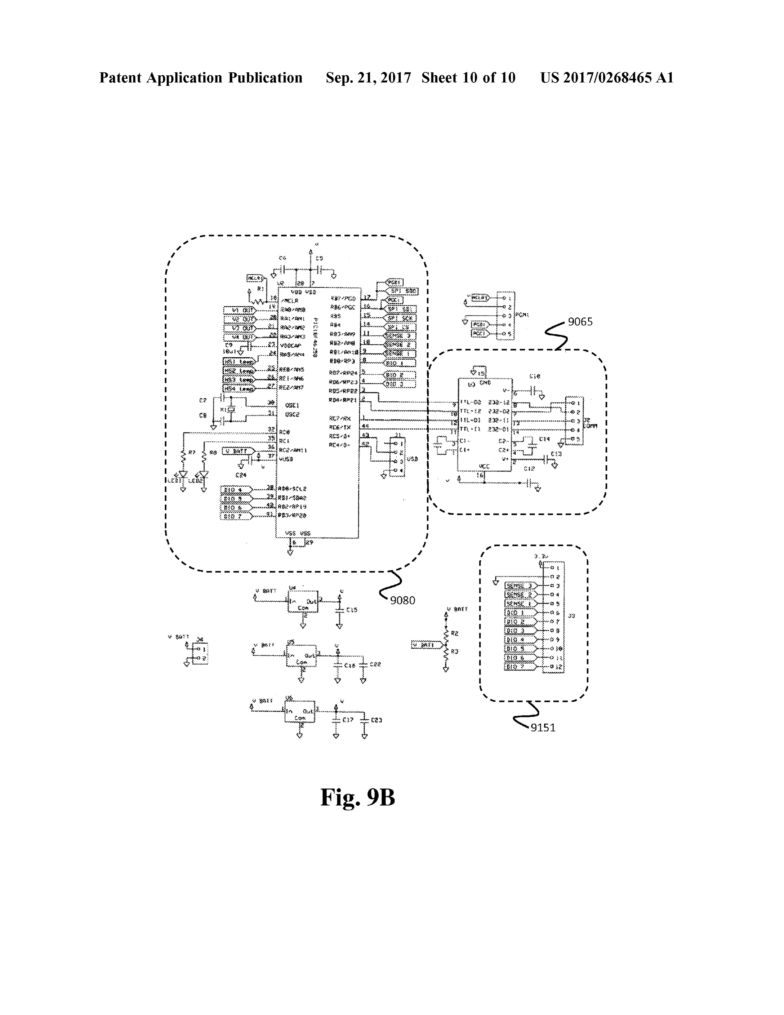
includes a WiFi transceiver. [0028 ] Referring now to the figures, wherein like elements [ 0022 ] FIG . 7 schematically illustrates a low volume are numbered alike throughout, FIG . 1 illustrates an elec hydrogen injection unit controller of the invention . tronic controller system 1000 that may control the delivery [0023] FIG . 8 schematically illustrates the power driver of hydrogen gas to an internal combustion engine . The components of a high volume hydrogen injection unit con device 1000 may include a vehicle or engine interface troller of the invention and , specifically , a power driver decoder 1020 , a main processor 1040 , a pulse width modu module . lation (PWM ) processor 1080, and a power driver 1100 . The [ 0024 ] FIGS. 9A and 9B schematically illustrate a multi system 1000 may receive data from a vehicle or engine phase main processor ( FIG . 9A ) and pulse width modulation interface 1010 (among other data sources), determine the (PWM ) processor (FIG . 9B ) components of a high volume applicable voltage that needs to be applied to a hydrogen hydrogen injection unit controller of the invention . source 1130 to produce a selected quantity of hydrogen to an DETAILED DESCRIPTION OF THE engine 1140 , and then apply that voltage to the hydrogen source 1130 to thereby produce the selected quantity of
INVENTION hydrogen proportional to the applied voltage .
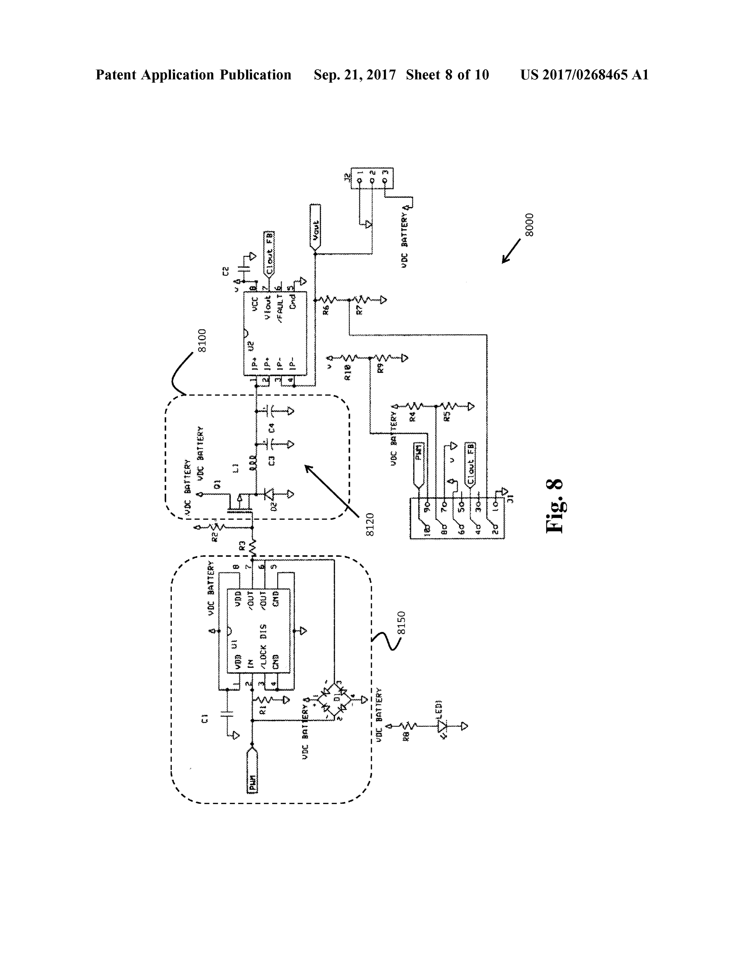
[0025 ] The disclosed invention is designed to operate in [0029 ] In accordance with associated FIGS. 1 - 3, solid conjunction with devices that provide hydrogen gas to lines connecting elements of the invention may indicate internal combustion engines at the point of combustion , for routes of communication between such elements . For example, to enhance the burning of fuels. By improving the example , communication between elements may be electri combustion process , harmful exhaust products (e.g., particu cal communication , optical communication , mechanical late matter) may be reduced . As used herein , the term communication , fluid communication ( e. g ., gaseous com “ internal combustion engine” may refer to reciprocating munication ), or anymeans of communication that allows the engines (e. g., 2 - stroke engines, 4 -stroke engines, and diesel indicated elements of the invention to interact by the trans engines), rotary engines, and continuous combustion mission and /or reception of electromagnetic radiation , radio engines (e.g., gas turbine engines and jet engines) that waves, light, voltage , current, or a combination thereof. convert fuel energy to other forms of energy such as (0030 ). The system 1000 includes main processor 1040 mechanical, electrical and such . Accordingly, an internal that may receive selected data from a vehicle interface 1010 , combustion engine , as encompassed within the present an external data source (not provided in FIG . 1 ), or a invention , may include internal combustion engines of any combination thereof. The main processor 1040 functions as size or fuel type, which may be used in a variety of the central hub of the system 1000 . The main processor 1040 applications (e . g ., electric generators , jet engines, diesel processes the selected data and compares it to a look - up locomotive engines, the engines of three -wheeler rickshaws, table (LUT) that may be stored on an electronic storage and the like ). medium within the main processor 1040 . By comparing the [0026 ] Devices that generate hydrogen gas include elec selected data to the LUT, the main processormay produce a trolysis devices having a fuel cell connected to a water processor signal and transmit the processor signalto a PWM supply that , upon application of a voltage , produce hydrogen processor 1080 . The main processor may be in communi and oxygen . Exemplary devices may be found in U . S . Pat. cation with a processor power source 1030 that provides Nos. 8,449,733 ; 8 ,449,734; 8,449 ,735 ; 8,449,736 ; 8 ,449, power to the main processor 1040 .
Page 14
US 2017 /0268465 A1 Sep . 21, 2017
[0031] The main processor may communicate with the faces, such as, WiFi, cellular, Industrial Scientific and Medi vehicle interface 1010 directly or, preferably , may commu cal (ISM ), and other radio systems, for example . nicate with the vehicle interface 1010 through a vehicle [0038 ] The communication circuitry 1060 may check for interface decoder 1020 that decodes the signals produced by any data to be received by the main processor 1040 from the the vehicle interface 1010 and provides a decoded signal to central servers. The communication circuitry 1060 may the main processor 1040 that may be read by the main download data , software updates, and/ or similar data if processor 1040 . Preferably , the vehicle interface 1010 may available from the central server. The communication cir be an On -Board Diagnostic (OBD ) device such as an cuitry 1060 may transmit data to the main processor 1040 OBD - II . Additionally, the vehicle interface decoder 1020 is after receiving data from the central server. Additionally , the preferably an OBD decoder. An exemplary OBD decoder is communication circuitry 1060 may have a real time clock set forth in FIG . 5 . (RTC ) to keep track of real world time, where such RTC may [ 0032 ] The main processor 1040 may store settings of the have a long life battery to keep the RTC active even when system for reference , accept changes to such settings , query external power is unavailable . The communication circuitry the vehicle interface decoder for status, data and other status 1060may check periodically when connectivity to the server questions, provide data to other sections, provide logging is available for current time to recalibrate the RTC for any data , pulse width modulation related data , and /or boot up drifts in the RTC are detected .
sequences . 0039 ] The external data source may provide external data [0033] The main processor 1040 may check for vehicle to the main processor 1040 where such external data may interface connectivity by communicating with the vehicle 's include, for example , fixed variables , types of data that may interface port (e.g ., OBD interface port ) located in the be excluded from processing, time, and/or user preferences. passenger cabin of a vehicle . The external data received from the external data source [0034 ] For example , the system 1000 may include an may also include software upgrades for software that may be OBD decoder that may connect to an industry standard used by the main processor 1040 or PWM processor 1080 . interface OBD bus . The standard interface OBD bus may The external data may also include LUTs, updated LUTs, or have a typical J1962 connector. In automotive devices , replacement LUTs . Optionally , the transceiver 1070 may be certain automobiles may have a variant of the connector. The replaced by a receiver that may receive a signal. Further OBD decoder circuit may use an off the shelf, commercially more , the transceiver 1070 may receive selected data from , available chip , as would be understood by those having for example , the external server ( e . g ., a central server ). The ordinary skill in the art, that translates the received OBD transceiver 1070 may also transmit the selected data data from the automobile into serial data for further pro received by the main processor 1040 and /or feedback data cessing . The OBD decoder circuit may accept a request for produced by other sensors of the system of the invention to information from the system and further may request it from the external server for recordation and review . the OBD bus and may receive replies from the OBD bus for [0040] As used herein , " selected data” may include, but is translation . not limited to , a vehicle temperature , a vehicle pressure , [ 0035 ] The external data source may be a user interface vehicle speed , an environmental temperature , an environ that can transfer data to the main processor 1040 or may be mental pressure , time, a vehicle status, or a combination an external server that can remotely provide data to the main thereof. More particularly, the " selected data ” may include , processor 1040 through communication circuitry 1060 hav but is not limited to , fuel system status, engine load , engine ing a transceiver 1070 . As used herein , a “ transceiver ” may coolant temperature , short term fuel percent trim , long term be a device having both a transmitter and a receiver that is fuel percent trim , fuel pressure , intake manifold absolute capable of transmitting and receiving data , simultaneously pressure, engine RPM , vehicle speed , timing advance , intake or alternatively, where data is transmitted and received air temperature , MAF air flow rate , throttle position , oxygen through electrical communication , electromagnetic commu sensor data , run time since engine start, distance traveled nication, optical communication , or a combination thereof. with malfunction indicator lamp on , fuel rail pressure , fuel [0036 ] The communication circuitry 1060 may receive level, barometric pressure , evaporation system vapor pres data from the main processor 1040 with statistical and sure, catalyst temperature, ambient air temperature , accel logging data . The communications circuitry 1060 may fur erator pedal position , fuel type, ethanol fuel percent, hybrid ther scan for connectivity to a central server via various battery pack data , fuel injection timing , engine oil tempera communication methods such as , for example, Bluetooth , ture , engine torque data , air flow data , diesel intake air flow WiFi, and cellular communication methods. An exemplary control and relative intake air flow position , exhaust gas communication circuit of the invention is set forth in FIG . 6 recirculation temperature , exhaust pressure , turbocharger having a WiFi transceiver. The communication circuitry RPM , turbocharger temperature , charge air cooler tempera 1060 may further upload data to the central servers via a ture , exhaust gas temperature , diesel particulate filter tem secure and encrypted method after connectivity to a server perature , engine run time, or a combination thereof. Prefer is detected . The communication circuitry 1060 may delete ably , the " selected data ” may include , but is not limited to , data from onboard memory once data written to the server engine RPM , engine load , vehicle speed , oxygen sensor is confirmed . The communication circuitry 1060 may also data , or a combination thereof. As used herein , “ oxygen transmit data such as its own identification , serial number , sensor data ” refers to data from an oxygen sensor that is and /or similar data to the server. The communication cir located on the vehicle ( e . g ., on a surface of the vehicle cuitry 1060 may also include a GPS receiver. exterior to the engine 1140 or interior to the engine 1140), [0037 ] Additionally , the communication circuitry 1060 where such data indicates the oxygen concentration at or can also seek and obtain a communication link via an about the oxygen sensor.
approved communication node. The communications cir - (0041] The system 1000 may also include recording cir cuitry 1060 may communicate via known wireless inter cuitry 1050 that may be in communication with one or both
Page 15
US 2017 /0268465 A1 Sep . 21, 2017
of the main processor 1040 and communication circuitry The driver power source 1110 provides a power source 1060. The recording circuitry 1050 may record system data voltage to the power driver 1100 . ( e. g ., data produced by an element of the system 1000 ) [0049 ] The processor power source 1030 and /or driver and /or external data onto a non -transitory storage medium . power source 1110 may include a battery ( e . g ., the battery of Storage media for containing data include, for example , the vehicle upon which the system 1000 is deployed or an floppy disks and diskettes , compact disk (CD )-ROMs independent battery for the system 1000 ), a DC generator (whether or not writeable ), DVD digital disks, RAM and ( e. g., solar generator, wind generator, gas powered genera ROM memories , SD cards, computer hard drives and back tor ), another power source derived from the vehicle upon up drives , external hard drives , " thumb" drives, and any which the system 1000 is deployed ( e. g ., an alternator of the other storage medium readable by a computer. vehicle ), a transmission line, or a combination thereof. The [0042 ] Furthermore , the recording circuitry 1050 may term battery is used herein to refer to an electro -chemical communicate with the main processor 1040 to periodically device comprising one or more electro -chemical cells and /or collect logging data ( e. g ., system data ). The recording cir fuel cells , and so a battery may include a single cell or plural cuitry 1050 , in addition to storage, can also accept com cells , whether as individual units or as a packaged unit . A mands for requests of data . The recording circuitry 1050 battery is one example of a type of an electrical power may hold configuration data . Moreover, the recording cir source suitable for a portable device . cuitry 1050 may handle data for upgrading the firmware of [0050 ] The power source voltage may be less than 100 sections of the system or update communication related volts. Preferably , the power source voltage is less than 50 information . volts . More preferably , the power source voltage is about 10 [0043] The system 1000 may further include a PWM volts to 25 volts . In certain aspects , the power source voltage processor 1080 that may receive and decode the processor is 12 volts or 24 volts .
signal from the main processor 1040 . The PWM processor [0051] The power driver 1100, in response to the received 1080 may convert the processor signal that is based upon the pulse stream ,may increase or decrease the magnitude of the LUT to provide a pulse stream . The pulse stream produced power source voltage to produce an applied voltage . The by the PWM processor 1080 has both a pulse stream time power driver 1100 may be a buck driver, a boost driver, or period and a pulse width , where both the pulse stream time a buck -boost driver. A buck driver may “ step - down " or period and the pulse width may bemodified by varying the decrease the power source voltage based on the received processor signal from the main processor. pulse stream to provide an applied voltage that is lesser in [ 0044 ] Additionally, the PWM processor 1080 may take magnitude than the power source voltage. For example, active measurements of the voltage and / or current at the load where the power source voltage is about 24 volts , the buck to provide a stable output. The PWM processor may use the driver may step -down the voltage to a value that is between active measurements of the output to recalculate the time period for the pulse stream and / or the width of each pulse in
O and 24 volts . A boost driver may “ step -up ” or increase the power source voltage based on the received pulse stream to the pulse stream to dynamically track and correct the pulse provide an applied voltage that is greater in magnitude than period and width . the power source voltage. For example , where the power [0045] The PWM processor 1080 may also check for fault source voltage is 24 volts , the boost driver may step -up the in the system 1000 such as overheating of power drivers, voltage to a value greater than 24 volts and , preferably , a potential short circuit , overload in a circuit, power issues in value that is between 24 and 50 volts . A buck -boost driver the power supply , communication disruption from the main may switch between buck and boost mode based on the processor, and / or safe start up and shutdown of the device application of the received pulse stream and provide logging information to the main processor 1040 . f0052] Indeed , the PWM processor 1080 may provide a [0046 ] The pulse stream produced by the PWM processor pulse stream to the power driver 1100 to provide voltages 1080 may be selected to produce a selected output at the lesser than and / or greater than the supply commonly called power driver 1100 . In the system 1000 , the PWM processor the buck -boost system . The PWM processor 1080 may 1080 may communicate directly with the power driver 1100 seamlessly switch between the buck mode and the boost or, for example , may be connected to the power driver 1100 mode where the power driver 1100 includes both a buck through a preamplifier 1090. The preamplifier 1090 may driver and a boost driver. Alternatively, a buck system or allow the PWM processor 1080 to provide an amplified boost system may be provided rather than the two in pulse stream to the power driver 1100 . Indeed , the pream combination .
plifier 1090 may be an electronic amplifier that provides an [0053] For example, the power driver 1100 may include a electrical signal to reduce the effects of noise and interfer MOSFET or a transistor drive , diodes, or a combination of ence by boosting the signal strength of the pulse stream , and similar components , a selection of filter components such as increasing the signal-to -noise ratio . inductors , capacitors in a calculated combination for a target 100471 The PWM processor 1080 may receive several load device . The selection of the components requires environmental sensor outputs such as , but not limited to , knowledge of the target load device 's characteristics with actual voltage delivered , current rate , gassing rate , tempera multiple components to allow the drive stage to generate a ture , unit temperature , and environment temperature . The voltage below the supply level or above the supply level PWM processor 1080 may use the foregoing sensor outputs known as a buck mode or boost mode , respectively . for immediate corrections, emergency shutoff, or similar [0054] The power driver 1100 may include an internal functions . The PWM processor 1080 may transmit such protection circuit that will protect the system from , for sensor outputs back to the main processor 1040 . example , overvoltages or back EMF voltages . The power [0048 ] The system may include a power driver 1100 that driver 1100 may also deliver power to a filter network 1120 , may receive the pulse stream from the PWM processor 1080 such as , for example , an LC filter network that may include and is in communication with a driver power source 1110 . capacitors and inductors .
Page 16
US 2017 /0268465 A1 Sep . 21, 2017
[0055 ] The filter network 1120 may perform a smoothen engine 1130 , as demonstrated in sensor network 1150 . The ing function based on the LC value combination that will sensor network 1150 allows for a sensor 1151 to provide provide , for example , a DC voltage at a voltage calculated information to the main processor 1040 and/or PWM pro by the main processor 1040 . cessor 1080 . Preferably , the one or more sensors 1151 may [0056 ] Furthermore, the PWM processor 1080 may sense be a hydrogen source power sensor , a current rate sensor, a the voltage at the output of the filter network 1120 (e .g ., LC gas rate sensor, a hydrogen source temperature sensor , a filter output) via a filter sensor to instantaneously correct any hydrogen source unit sensor, an output voltage sensor, drifts or any other compensations that may be required via hydrogen concentration sensor, or a combination thereof. a closed feedback loop. The PWM processor 1080 may also For example, sensor 1151 may include a hydrogen source transmit the voltage at the LC filter output to the main power sensor that provides data output describing the power processor 1040 for recalibration of the calculation used for provided to the hydrogen source in real time. A current rate production of the processor signal, as needed . An LC filter sensor may include one or more sensors that provide data at the PWM processor 1080 may have an output that is output describing the current at the processor power source delivered to a hydrogen source 1130 for hydrogen produc 1030 , driver power source 1110 , power driver 1100 , or tion . Preferably , the power driver 1100 provides the applied hydrogen source 1130 , for example . A gas rate sensor may voltage to the filter network 1120 , which thereby provides the applied voltage, now filtered , to the hydrogen source include one or more sensors placed at the hydrogen source 1130 or engine 1140 to determine the rate and concentration 1130 . of hydrogen provided from the hydrogen source 1130 to the [0057] Hydrogen source 1130 of the invention may engine 1140 . Additionally , a gas rate sensor may be provided include an electrolyzer hydrogen source, such as , for at the exhaust of the engine 1140 to determine the amount of example , an electrolytic hydrogen generator as described in hydrogen that is being exhausted and not combusted . A U .S . Pat. Nos. 8 , 449,733; 8 , 449,734 ; 8 ,449,735 ; 8 ,449,736 ; hydrogen source temperature sensor may be provided at the 8 ,449,754 ; 8 ,454 , 808; 8 ,499 ,722 ; and 8 ,757 ,107 ; each of hydrogen source 1130 to determine the temperature of the which is incorporated by reference herein . The electrolyzers hydrogen source 1130 . A hydrogen source unit sensor may described in the foregoing disclosures produce a selected be provided at the hydrogen source 1130 to provide data amount of hydrogen and oxygen upon the application of a output indicating whether the hydrogen source 1130 is voltage . Consequently , the present system 1000 may modu functioning and , for example , whether there is a sufficient late the amount of hydrogen produced by varying the quantity of water at the hydrogen source 1130 when the applied voltage , as set forth herein . hydrogen source 1130 includes an electrolyzer. An output [0058 ] The foregoing hydrogen source 1130 , which may voltage sensor may include one or more sensors that provide be in communication with the power driver 1100 either data output describing the voltage at the processor power directly or through the filter network 1120 , may then be in source 1030 , driver power source 1110 , power driver 1100 , gaseous communication with the engine 1140 . Accordingly , or hydrogen source 1130 , for example. The system 1000 hydrogen gas originating at the hydrogen source may be may also include a hydrogen concentration sensor that, in injected into the air intake of the engine (or to a combustion combination with the gas rate sensor, may provide a data chamber of the engine) to enhance combustion . output that indicates the concentration of hydrogen gas after 10059 ] The system 1000 may further include a safety production by the hydrogen source 1130 . module 1135 that may monitor the overall operation of the system 1000 that, in case of an accident or failure , as a whole [0062] The foregoing sensors 1151 in the sensor network or in part, of the system 1000 , the safety module 1135 may 1150 provide feedback data on the operation of the system halt the production of hydrogen and/or vent any hydrogen 1000 to the main processor 1040 and/or PWM processor stored by the system at the hydrogen source 1130 or engine 1080 . The main processor 1040 and/ or PWM processor 1080 1140 to the atmosphere . The safety module 1135 may be in include processor circuitry that allows for the processing of communication ( e .g ., electrical and/ or fluid communication ) the selected data in conjunction with the feedback data to with at least one of the hydrogen source 1130 and engine dynamically adjust the processor signal, pulse stream , and /or 1140 . Additionally, the safety module 1135 may be in LUT in real time to optimize the operation of the system communication with one or more sensors 1151 and may 1000 . For example , if a gas rate sensor at the exhaust of the have circuitry to receive a fault signal from the one or more engine 1140 indicates that the hydrogen provided to the sensors 1151 thatmay cause the safety module 1135 to halt engine 1140 is not completely combusting , the main pro the production of hydrogen and /or vent any hydrogen stored cessor can dynamically adjust the LUT and processor signal by the system at the hydrogen source 1130 or engine 1140 to produce an applied voltage at the power driver 1100 , to the atmosphere . In certain aspects of the invention , the which results in a decreased production of hydrogen at the safety module 1135 may be a valve in line with the hydrogen hydrogen source 1130 .
source 1130 and engine 1140 configured to prevent back [0063] In an alternative embodiment as set forth in FIG . 2 , flow , vent hydrogen stored at the hydrogen source 1130 , and a system 2000 of the invention may have a multiphase power halt the production of hydrogen to the engine 1140 . driver system wherein the PWM processor 2080 may syn [0060] In certain preferred embodiments, the safety mod chronously operate multiple PWM signals in such a way that ule 1135 may be a fail-safe valve , that halts the production it can power up multiple power driver stage units such as of hydrogen and/or vents any hydrogen stored by the system those provided in the power driver 2100 , which provides a at the hydrogen source 1130 in case of an accident or plurality of power drivers 2101, 2102 , 2103 in parallel to malfunction of the system 1000 . allow a cooler operation of the system . This is a multi-phase [0061] Additionally, the system 1000 may also utilize one PWM system . The PWM processor 2080 may also operate or more sensors 1151 in communication with main processor a cooling fan , when required , to keep the power drive stage 1040 , PWM processor 1080 , hydrogen source 1130 , and /or and related components at a stable temperature . Further
Page 17
US 2017 /0268465 A1 Sep . 21, 2017
more , similar to other systems of the invention , the PWM [0068] In certain preferred embodiments, the safety mod processor 2080 may be connected to the power driver 2100 ule 3135 may be a fail-safe valve, that halts the production through a preamplifier 2090 . of hydrogen and /or vents any hydrogen stored by the system [ 0064 ] Furthermore , the power driver 2100 operates the at the hydrogen source 3130 in case of an accident or multiple power drive stages in parallel by operating under a malfunction of the system 3000 .
multiphase mode . The power driver 2100 is connected to a [0069 ] The systems of the invention may further include, driver power source 2110 . This allows for the driving of or be in communication with , a central data facility that multiple power drivers ( e. g., 2101, 2102 , 2103 ) in a timed includes the central server system and may include a col manner to distribute the amount of power passing through lection of servers that provide an information database , each power drive stage to allow a much higher operating authentication server, and report generation service . The power range and further allow the power drive stage to central server may always be on to receive data for a system remain at a lower temperature. This allows the system 2000 of the invention . The central server may receive packets of to be power efficient. Power drivers 2101, 2102 , and 2103 data from the communication server and may log a unique may be buck drivers, boost drivers , or buck -boost drivers . identification , data , and timestamps into the database for a When operating in a multiphase mode , the filter network system of the invention.
2120 collects the increased or decreased voltage produced [0070 ] The central server may include a database that is by the plurality of power drivers 2100 and smooths the available for analysis by the end user or operator. The central applied voltage to provide an applied voltage to the hydro server may also host updates and calibration values for each gen source ( e .g ., hydrogen source 1130 ). unit in operation .
[0065 ] Other advantages of the multistage driver system [0071] In additional aspects, the systems of the invention include synchronization of the plurality of drivers and low ( e. g., 1000 , 2000 , 3000 )may include a display for displaying ripple current output. system data and information regarding the operation of the 0066 ] In an additional aspect of the invention as set forth system to a user. The systems of the invention may include in FIG . 3 , a system 3000 of the invention may include a a user interface and may allow for a user to program aspects hydrogen source 3130 having a hydrogen storage container of the system either through a direct connection to the 3131 . The storage container 3131 may contain a volume of system or remotely . The systems of the invention may also hydrogen gas. The hydrogen source actuator 3132 may include a power on /off switch to allow a user to disengage include a valve that opens in response to an applied voltage . the system . The systems of the invention may include a Therefore , a system 3000 that includes a quantity of hydro housing for enclosing the components of the system within gen in the hydrogen storage container 3131 may deliver the housing . The housing may be located within a compart hydrogen gas to an engine 3140 upon delivery of the applied ment of a vehicle .
voltage to the hydrogen source actuator 3132 . For example , [0072 ] Furthermore, the system of the invention may be the hydrogen source actuator 3132 may be designed to hold enclosed or prepared from such materials known in the art the valve to the hydrogen storage container 3131 open for a that it may be operated in different environmental systems time proportional to the magnitude of the applied voltage . including under -water, on -board a vehicle , in a cold climate , Furthermore, such a system 3000 , as set forth in other in a hot climate , on earth , in space , or on an extraterrestrial systems of the invention , may include a power driver 3100 body.
in communication with a driver power source 3110 . The [0073] The present invention also includes a method of power driver 3100 may then communicate with the hydro use 4000 as demonstrated in FIG . 4 . gen source actuator 3132 through the filter network 3120 . 10074 ] In the exemplary method 4000 , a system for pro 100671. The system 3000 may further include a safety viding hydrogen gas to an internal combustion engine is module 3135 that may monitor the overall operation of the provided . The system may be powered on (step 4090 ) when system 3000 that, in case of an accident or failure , as a whole the engine of a vehicle is powered on and the system of the or in part, of the system 3000 , the safety module 3135 may invention may check for connectivity to the vehicle interface halt the production of hydrogen to the engine 3140 and may ( e . g ., OBD device ) ( step 4010 ) . Alternatively , activation of vent hydrogen stored at the hydrogen storage container the system may be delayed for a selected period of time by 3131, the hydrogen source actuator 3132 , and/or engine a user. If the system is connected to the vehicle interface 3140 to the atmosphere. The safety module 3135 may be in ( step 4020 ), the system may check devices connected to the communication ( e . g ., electrical and / or fluid communication ) system ( e. g., main processor, PWM processor, power driv with at least one of the hydrogen storage container 3131 , the ers ) ( step 4040) . If the system is not connected to the vehicle hydrogen source actuator 3132 , and engine 3140 . Addition interface ( step 4030 ) , the system of the invention may be set ally , the safety module 3135 may be in communication with to sleep at the main processor and may wait to check for one or more sensors ( e.g ., one or more sensors 1151 ) and vehicle interface connectivity after a programmed delay . may have circuitry to receive a fault signal from the one or [0075 ] After checking for, and confirming the connectivity more sensors thatmay cause the safety module 3135 to halt of, the devices connected to the system , the system may the production of hydrogen and / or vent any hydrogen stored acquire selected data from the vehicle interface (step 4050) by the system at the hydrogen storage container 3131 , the and then process the selected data from the vehicle interface hydrogen source actuator 3132 , and /or engine 3140 to the ( step 4060 ), which may include decoding the data from the atmosphere . In certain aspects of the invention , the safety vehicle interface to prepare such data for analysis and module 3135 may be a valve in line with the hydrogen processing by the main processor. At this stage, the system storage container 3131, the hydrogen source actuator 3132 , may also receive selected data from an external data source . and engine 3140 configured to both vent hydrogen stored at After processing, the main processor may compare the the hydrogen storage container 3131 and halt the production selected data from the vehicle interface (and /or external data of hydrogen to the engine 3140. source ) to a look up table (LUT) to determine the value of
Page 18
US 2017 /0268465 A1 Sep . 21, 2017
a processor signal that should be sent to the PWM processor on the pulse stream from the PWM processor, may result in to achieve a desired applied voltage thatresults in an amount an applied voltage that is lesser in magnitude than the power of hydrogen gas being delivered to the engine ( step 4070) . source voltage (i.e ., a buck driver system ). Additionally, if there is feedback data being provided by [0081 ] Alternatively, the applied voltage may be filtered sensors of the system ( step 4270 ), the feedback data may be with a filter network (step 4200 ) to provide a filtered applied processed with the selected data to dynamically adjust the voltage . The output power pulse stream and/ or applied LUT and /or the processor signalbeing provided to the PWM voltage produced by the power driver may be sensed by a processor. sensor at the power driver (step 4240 ) and the output [0076 ] Moreover , selected data, feedback data , system parameters associated with the power driver may be con data from the PWM processor, and /or system data from the verted to feedback data by a sensor network (step 4260 ). main processor may be saved to an on -board storage Indeed , the method of the invention may include a step of medium ( step 4080 ) . After the system is powered on ( step sensing at least one of a hydrogen source power signal, a 4090), the system may determine if it is wirelessly con current rate signal, a gas rate signal, a hydrogen source nected to a central server or in communication with an temperature signal, a hydrogen source unit signal, an envi external receiver (step 4100 ). If the system is not in com ronment temperature signal, an output voltage signal, and a munication with a central server or external receiver, itmay hydrogen concentration signal, where such signals may be continue to check for such connectivity after a programmed converted into feedback data that may be processed at the delay . However, if the system finds connectivity with a main processor or PWM processor.
central server, for example, the system may transmit saved [0082 ]. The applied voltage may then be transmitted to a selected data , feedback data , and/ or system data to the hydrogen source (step 4210 ) designed to receive the voltage central server ( step 4110 ). After transmission of the saved and provide an amount of hydrogen to an internal combus data , the system may delete such data from the on -board tion engine that is proportional to the applied voltage (step storage medium . 4220 ). The hydrogen source may be an electrolyzer as 10077] In addition , the system of the invention may com described above , ormay include a hydrogen gas actuator in municate with a central server, for example , to determine if fluid communication with a hydrogen gas storage container, there is a modified LUT, replacement LUT, and / or software wherein the gas actuator may open and release an amount of update available for download (step 4120 ). If no such hydrogen from the hydrogen gas storage that is proportional modified LUT, replacement LUT, or software update is to the applied voltage .
available , the system may continue operation and may [0083 ] Additionally, after the applied voltage is transmit repeat the process steps 4100 , 4110 , and 4120 . If there is a ted to the hydrogen source ( step 4210 ), the process may be modified LUT, replacement LUT, and /or software update repeated ( step 4230 ) by again checking the vehicle interface available, the system may halt operation and may update the connectivity ( step 4010 ).
LUT and /or software (step 4130 ) . Upon completion of the [0084 ] Moreover, the method of the invention may further update, the system may resume ( step 4140 ). include the steps of detecting a fault signal at any sensor that [0078 ] Turning to the continued operation of the system , indicates the occurrence of an accident or malfunction of a after production of the processor signal, the main processor system of the invention , and transmitting the fault signal to transmits the processor signal data to the PWM processor a safety module operably associated with the hydrogen ( step 4150 ) . The processor signal may be transmitted from source and /or the engine to , upon reception of the fault the main processor to the PWM processor through electrical signal, halt the production ofhydrogen to the engine and /or transmission , radio transmission , optical transmission , cel vent hydrogen stored at the system of the invention ( e.g ., at lular transmission or a combination thereof. the hydrogen source ) to the atmosphere . [0079] The PWM processor decodes the digital processor [0085 ] The present arrangement of method steps may be signal and checks the voltage to be generated by a power embodied as a computer implemented process or processes driver ( step 4160 ). The PWM processor then prepares a and / or apparatus for performing such computer - imple pulse stream based upon the processor signal having a pulse mented process or processes , and can also be embodied in stream period and a pulse width selected to produce an the form of a tangible storage medium containing a com applied voltage by a power driver ( step 4170 ). The pulse puter program or other machine-readable instructions stream is then transmitted from the PWM processor to the (herein " computer program ” ), wherein when the computer power driver ( step 4180 ) . The pulse stream may be trans program is loaded into a computer or other processor ( herein mitted directly to the power driver or, preferably, may be " computer ” ) and/ or is executed by the computer, the com transmitted via a preamplifier that amplifies the pulse stream puter becomes an apparatus for practicing the process or before reception by the power driver .Accordingly , step 4180 processes . Storage media for containing such computer may further include the step of amplifying the pulse stream program include, for example , floppy disks and diskettes , to reduce the signal-to -noise ratio . compact disk (CD )-ROMs (whether or not writeable ), DVD [0080 ] A power source may communicate a power source digital disks , RAM and ROM memories, computer hard voltage to the power driver , with the communicated voltage drives and back -up drives, SD cards , external hard drives , being less than about 50 volts , but, preferably , about 10 to " thumb” drives, and any other storage medium readable by 25 volts (step 4250 ). The power driver may then provide a computer. The process or processes can also be embodied based on the pulse stream from the PWM processor to in the form of a computer program , for example , whether provide an applied voltage (step 4190 ). In certain aspects, stored in a storage medium or transmitted over a transmis the power pulse stream , based on the pulse stream from the sion medium such as electrical conductors, fiber optics or PWM processor, may result in an applied voltage that is other light conductors , or by electromagnetic radiation , greater in magnitude than the power source voltage (i.e., a wherein when the computer program is loaded into a com boost driver system ). Alternatively, the power stream , based puter and/or is executed by the computer, the computer
Page 19
US 2017 /0268465 A1 Sep . 21, 2017
becomes an apparatus for practicing the process or pro filter circuitry 8100 that includes a filter network 8120 . The cesses. The process or processes may be implemented on a power driver is provided here as buck driver 8150 . general purpose microprocessor or on a digital processor [0091] The High Volume system also includes a main specifically configured to practice the process or processes. processor and PWM processor as shown in FIGS. 9A and When a general-purpose microprocessor is employed, the 9B , respectively . As shown in FIG . 9A , the High Volume computer program code configures the circuitry of the system includes multiphase processor 9040 ( i. e ., main pro microprocessor to create specific logic circuit arrangements. cessor ) thatmay be connected to multiple buck drivers ( such Storage medium readable by a computer includes medium as buck driver 8150 ). As shown in FIG . 9B , the High Volume being readable by a computer per se or by another machine system includes PWM processor 9080 that is connected to that reads the computer instructions for providing those communication transceiver 9065 and multiphase processor instructions to a computer for controlling its operation . Such 9040 , and has sensor input 9151 that receives sensor data at machines may include , for example , a punched card reader, the PWM processor 9080 .
a magnetic tape reader, a magnetic card reader, a memory [0092] In the High Volume system of FIGS. 8 and 9, the card reader, an optical scanner, as well as machines for power driver module 8000 is connected to a 24 V power reading the storage media mentioned above.
[0086 ] Without limiting the invention in any way , the source. The buck driver 8150 may reduce the 24 V voltage invention may be described further in the following and provide an applied voltage to a hydrogen source that is examples. connected to the High Volume system . 10093 ]. Anumber of patent and non -patent publications are
Examples cited herein in order to describe the state of the art to which this invention pertains. The entire disclosure of each of these
Example 1 : Exemplary Components Including an publications is incorporated by reference herein . On -Board Diagnostic (OBD ) Decoder Module and [0094] While certain embodiments of the present inven a Communication Module tion have been described and /or exemplified above , various [0087 ] As shown in FIG . 5 , an OBD Decoding module other embodiments will be apparent to those skilled in the art 5000 is provided having an OBD Decoder 5020 connected from the foregoing disclosure . The present invention is , to a microprocessor 5040 and a communication transceiver therefore , not limited to the particular embodiments described and/ or exemplified , but is capable of considerable 5065 . The OBD Decoder 5020 is connected to a vehicle variation and modification without departure from the scope interface 5010 that allows for the connection between the and spirit of the appended claims. OBD Decoder 5020 and a vehicle ' s On -Board Diagnostic system . [0095 ] Moreover, as used herein , the term “ about” means 10088 ] As shown in FIG . 6 , a communication module that dimensions, sizes , formulations, parameters , shapes and 6000 is provided having a real time clock 6001, a WiFi other quantities and characteristics are not and need not be transceiver 6063 , an on -board storage system 6050 , and a exact, but may be approximate and /or larger or smaller, as communication transceiver 6065 connected to communica desired , reflecting tolerances, conversion factors, rounding tion circuitry 6060 . Communication circuitry 6060 is con off, measurement error and the like , and other factors known nected to microprocessor 5040 through the communication to those of skill in the art. In general, a dimension, size, transceiver 6065 , which allows for communication between formulation , parameter , shape or other quantity or charac the OBD module 5000 and the communication module teristic is “ about” or “ approximate ” whether or not expressly 6000 . stated to be such . It is noted that embodiments of very different sizes , shapes and dimensions may employ the
Example 2: A Low Volume Hydrogen Gas System described arrangements.
[0089 ] Low Volume Hydrogen Gas system 7000, used [0096 ] It is noted that various sensor values and alarm primarily for cars , is provided in FIG . 7 . The Low Volume values represent actual physical conditions of different places and /or different equipment and / or different parts of an system 7000 includes a buck -boost power driver . Specifi installation or vessel or other place , e . g ., generally local cally , the Low Volume system 7000 includes a communi conditions, that are transformed by the system and method cation transceiver 7065 and a power driver 7150 connected described herein to provide a representation of the overall to a pulse width modulation (PWM ) processor 7080 through filter / sensor circuitry 7100 . The filter/sensor circuitry 7100 state and /or condition of the installation , vessel or place, e.g . includes a filter network 7120 . The power driver 7150 has a a representation of the complete installation , vessel and / or buck driver 7151 and a boost driver 7153 . The Low Volume place . That representation may be transformative of a rep system 7000 is further connected to a 12 V power source . As resentation of a nominal overall state and / or condition described herein , the power driver 7150 can step - down (via thereof, e. g ., in a prior or different condition and/ or time, to the buck driver 7151 ) or step - up ( via the boost driver 7153 ) a representation of an actual overall state and /or condition the 12 V voltage from the power source to provide an thereof, e . g ., in a present or more recent or otherwise applied voltage to a hydrogen source connected to the Low different condition and/or time. Further, the system and Volume system . method generates tasks and commands that are executed to transform the installation , vessel or place into a different
Example 3: A High Volume Hydrogen Gas System configuration, i.e . into a different installation , vessel or place , and a representation of that different configuration is [0090 ] A High Volume Hydrogen Gas system used for provided or displayed , e . g ., to human operators . The system trucks and larger vehicles is provided in FIGS. 8 and 9 . As described herein may include one or more general purpose shown in FIG . 8 , the High Volume system includes power and /or special purpose computers , or microprocessors or driver module 8000 . The power driver module 8000 has other processors, and the method described herein may be
Page 20
US 2017 /0268465 A1 Sep . 21, 2017
performed in part by one or more general purpose and /or data , diesel intake air flow control and relative intake air special purpose computers , or microprocessors or other flow position , exhaust gas recirculation temperature , exhaust processors. pressure , turbocharger RPM , turbocharger temperature , [0097] Furthermore, the transitional terms " comprising ” , charge air cooler temperature , exhaust gas temperature , " consisting essentially of” and “ consisting of” , when used in diesel particulate filter temperature , engine run time, or a the appended claims, in original and amended form , define combination thereof.
the claim scope with respect to what unrecited additional 3 . The system of claim 1 , wherein the selected data claim elements or steps, if any, are excluded from the scope comprises at least one of engine RPM , engine load , vehicle of the claim (s ). The term " comprising" is intended to be speed , oxygen sensor data , or a combination thereof. inclusive or open - ended and does not exclude any addi 4 . The system of claim 1, wherein the sensor comprises a tional, unrecited element,method , step or material. The term hydrogen source power sensor, a current rate sensor, a gas “ consisting of excludes any element, step or material other rate sensor , a hydrogen source temperature sensor, a hydro than those specified in the claim and , in the latter instance , gen source unit sensor, an environment temperature sensor , impurities ordinary associated with the specified material(s). an output voltage sensor, an output current sensor, a hydro The term " consisting essentially of” limits the scope of a gen concentration sensor, or a combination thereof. claim to the specified elements , steps or material( s ) and 5 . The system of claim 1, comprising communication those that do not materially affect the basic and novel circuitry in communication with the main processor, said characteristic (s ) of the claimed invention . All systems, communication circuitry configured to receive external data devices, and methods described herein that embody the from the external data source . present invention can , in alternate embodiments , be more 6 . The system of claim 5 , wherein the communication specifically defined by any of the transitional terms " com circuitry comprises recording circuitry configured to record prising ," " consisting essentially of,” and “ consisting of.” system data onto a non -transitory data storage device . What is claimed is: 7 . The system of claim 5 , wherein the communication 1. A system for providing hydrogen gas to an internal circuitry comprises a communications circuitry transceiver combustion engine, wherein the system is configured to configured to transmit at least one of the selected data and communicate with a hydrogen source that provides hydro feedback data to an external receiver. gen gas to the internal combustion engine in an amount proportional to an applied voltage, the system comprising: 8 . The system of claim 7 , wherein the communications a . a main processor configured to receive selected data circuitry transceiver comprises an optical transceiver, an from at least one of a vehicle interface device and an electrical transceiver, a radio transceiver, a cellular trans external data source, said main processor configured to ceiver, or a combination thereof.
generate and transmit a processor signal based on the 9 . The system of claim 1 , wherein the main processor selected data ; comprises a non - transitory computer readable medium hav b . a pulse width modulation (PWM ) processor in com ing computer readable program code embodied therein , the munication with the main processor configured to computer readable program code comprising a look -up table receive the processor signal, said PWM processor con for selection of the processor signal in response to the figured to provide a pulse stream based upon the selected data .
processor signal, wherein the pulse stream comprises a 10 . The system of claim 9 , wherein the main processor is pulse stream time period and a pulse width ; and configured to dynamically adjust the look -up table based c . a power driver in communication with the PWM upon the feedback data received from the sensor after the processor and a power source , the power driver con provision of the applied voltage .
figured to receive the pulse stream from the PWM 11 . The system of claim 1 , wherein the power driver processor and increase or decrease the magnitude of a comprises a buck driver, a boost driver, a buck -boost driver, power source voltage to provide an applied voltage to or a combination thereof.
a hydrogen source ; wherein at least one of the main 12 . The system of claim 1, comprising a power source processor and the PWM processor are configured to configured to provide a power source voltage of less than 50 receive feedback data from a sensor after the provision volts to the power driver.
of an applied voltage to dynamically adjust at least one 13 . The system of claim 12 , wherein the power driver of the processor signal and pulse stream during opera comprises a buck driver configured to reduce the power tion of the system . source voltage to a magnitude that is less than the power 2 . The system of claim 1 , wherein the vehicle interface source voltage .
device is an on -board diagnostic (OBD ) device and the 14 . The system of claim 12 , wherein the power driver selected data comprises at least one of fuel system status, comprises a boost driver configured to increase the power engine load , engine coolant temperature , short term fuel source voltage to a magnitude that is greater than the power percent trim , long term fuel percent trim , fuel pressure , intake manifold absolute pressure, engine RPM , vehicle source voltage.
speed , timing advance , intake air temperature, MAF air flow 15 . The system of claim 12 , wherein the power driver rate , oxygen sensor data, run time since engine start, dis comprises a buck -boost driver configured to increase the tance traveled with malfunction indicator lamp on , fuel rail power source voltage to a magnitude that is greater than the pressure , fuel level, barometric pressure , evaporation system power source voltage , and decrease the power source volt vapor pressure , catalyst temperature, ambient air tempera age to a magnitude that is less than the power source voltage . ture , throttle position , accelerator pedal position , fuel type, 16 . The system of claim 1 , wherein the power driver ethanol fuel percent, hybrid battery pack data , fuel injection comprises a plurality of buck drivers , boost drivers , buck timing , engine oil temperature , engine torque data , air flow boost drivers , or a combination thereof.
Page 21
US 2017 /0268465 A1 Sep . 21, 2017
17 . The system of claim 1, wherein the power driver system vapor pressure , catalyst temperature , ambient air comprises a power filter configured to smooth the applied temperature , accelerator pedal position , fuel type, ethanol voltage. fuel percent, hybrid battery pack data , fuel injection timing , 18 . The system of claim 17 , comprising a power filter engine oil temperature, engine torque data , air flow data , sensor configured to sense at least one of voltage and current diesel intake air flow control and relative intake air flow at the power filter , wherein the PWM processor is configured position , exhaust gas recirculation temperature , exhaust to communicate with the filter sensor and correct any drift in pressure , turbocharger RPM , turbocharger temperature, the voltage or current at the filter. charge air cooler temperature , exhaust gas temperature , 19 . The system of claim 1 , wherein the hydrogen source diesel particulate filter temperature , engine run time, or a comprises an electrolyzer configured to generate hydrogen combination thereof.
gas . 27 . The method of claim 24 , wherein the selected data 20 . The system of claim 1, wherein the hydrogen source comprises at least one of engine RPM , engine load , vehicle comprises a hydrogen gas actuator in fluid communication speed , oxygen sensor data , or a combination thereof. with a hydrogen gas storage, wherein the hydrogen gas 28 . The method of claim 24 , comprising the step of actuator is configured to release an amount of hydrogen transmitting at least one of the selected data and feedback from the hydrogen gas storage in response to the applied data to an external receiver.
voltage. 29 . The method of claim 28 , wherein transmitting com 21. The system of claim 1 , wherein the internal combus - prises at least one of optical transmission, electrical trans tion engine comprises a reciprocating engine , a rotary mission , radio transmission , and cellular transmission . engine , or a continuous combustion engine . 30 . The method of claim 24, comprising the step of 22 . The system of claim 1 , comprising a safety module in storing at least one of the selected data and feedback data communication with at least one of the engine and hydrogen onto a non -transitory storage device . source , the safety module configured to prevent back flow , 31 . The method of claim 24, comprising the step of vent hydrogen stored at the hydrogen source , or halt pro sensing at least one of a hydrogen source power signal, a duction of hydrogen . current rate signal, a gas rate signal, a hydrogen source 23 . The system of claim 22, wherein the safety module temperature signal, a hydrogen source unit signal, an envi comprises a valve in communication with the hydrogen ronment temperature signal, an output voltage signal, and a source . hydrogen concentration signal.
24 . A method for providing hydrogen gas to an internal 32 . The method of claim 24 , wherein the step of providing combustion engine, the method comprising the steps of: a power source voltage to a power driver comprises the step a . acquiring selected data from a vehicle comprising an of filtering and smoothing the applied voltage. internal combustion engine ; 33. The method of claim 32 , comprising the step of b .processing the selected data and comparing the selected sensing at least one of voltage and current at a power filter data to a look up table to generate a processor signal configured to filter and smooth the applied voltage and based on the selected data ; determine the presence of any drift in the voltage or current c . producing a pulse stream based on the processor signal, at the filter.
the pulse stream comprising a pulse stream time period 34 . The method of claim 24 , wherein the power source and a pulse width ; voltage is less than 50 volts.
d . providing a power source voltage to a power driver and 35 . The method of claim 24 , wherein the power driver changing the magnitude of the power source voltage comprises a buck driver , a boost driver, a buck -boost driver, based on the pulse stream to provide an applied voltage , or a combination thereof.
wherein changing the magnitude of the power source 36 . The method of claim 24 , comprising the step of voltage comprises increasing or decreasing the magni transmitting the processor signal from a main processor to a tude of the power source voltage ; pulse width modulation (PWM ) processor, wherein the e . providing the applied voltage to a hydrogen source to PWM processor is configured to produce the pulse stream . produce an amount of hydrogen gas proportional to the 37 . The method of claim 36 , wherein the step of trans applied voltage; and mitting the processor signal from the main processor to the f. receiving feedback data from a sensor after providing PWM processor comprises electrical transmission , radio the applied voltage to the hydrogen source , and transmission , optical transmission , cellular transmission , or dynamically adjusting at least one of the processor a combination thereof.
signal and pulse stream based on the feedback data . 38 . The method of claim 24 , further comprising the step 25 . The method of claim 24 ,wherein the step of acquiring of repeating steps a through f.
selected data comprises acquiring the selected data from at 39 . Themethod of claim 24 ,wherein the hydrogen source least one of an on -board diagnostic (OBD ) device and an comprises an electrolyzer configured to generate hydrogen external data source . gas .
26 . The method of claim 24 , wherein the selected data 40 . The method of claim 24 , wherein the hydrogen source comprises at least one of fuel system status, engine load , comprises a hydrogen gas actuator in fluid communication engine coolant temperature, short term fuel percent trim , with a hydrogen gas storage , wherein the hydrogen gas long term fuel percent trim , fuel pressure , intake manifold actuator is configured to release an amount of hydrogen absolute pressure , engine RPM , vehicle speed , timing from the hydrogen gas storage in response to at the applied advance , intake air temperature, MAF air flow rate , throttle voltage .
position , oxygen sensor data , run time since engine start, 41. The method of claim 24, wherein the internal com distance traveled with malfunction indicator lamp on , fuel bustion engine comprises a reciprocating engine, a rotary rail pressure, fuel level, barometric pressure, evaporation engine, or a continuous combustion engine .
Page 22
US 2017 /0268465 A1 Sep . 21, 2017
42 . The method of claim 24 , comprising detecting a fault signal at a sensor that indicates the occurrence of an accident or malfunction and transmitting the fault signal to a safety module operably associated with the hydrogen source to , upon reception of the fault signal, halt the production of hydrogen to the internal combustion engine.
43 . The method of claim 24 , comprising detecting a fault signal at a sensor that indicates the occurrence of an accident or malfunction and transmitting the fault signal to a safety module operably associated with the hydrogen source to , upon reception of the fault signal, vent hydrogen stored at the hydrogen source .
Provenance
- Collection
- Patents citing this work
- Original assignee
- Imagestatistics Inc
- Pages
- 22
- Method
- pdftotext (the PDF's own text layer) + pdftoppm 300dpi page scans
- Patent office record
- patents.google.com →
- Source
- Google Patents citing-documents table
- Inventors
- Vikram Agrahar; Joseph Gaetz; Lalit K. Aggarwal; Imagestatistics Inc
- Published
- 2017-09-21
- Transcribed from
- patentimages.storage.googleapis.com →