patent · US4635641
Multi-element electrode
13 January 1987
Page 1
United States Patent (19) 11 Patent Number: 4,635,641 Hoffman 45) Date of Patent: Jan. 13, 1987 (54) MULT-ELEMENT ELECTRODE 4,062,364 12/1977 Masaki ................................ 128/803 75) Inventor: Kent C. Hoffman, Cockeysville, Md. 4,082,086 4/1978 Page et al. .......................... 128/640 4,367,755 1/1983 Bailey .................................. 128/802 (73) Assignee: Murray Electronics Associates 4,524,087 6/1985 Engel .................................. 128/640 Limited, Hunt Valley, Md. Primary Examiner-Kyle L. Howell 21 Appl. No.: 788,215 Assistant Examiner-Randy Citrin
Attorney, Agent, or Firm-Nixon & Vanderhye
(51) Int, Cl............. - - A -- O - - A61B5/04
(52) U.S. Cl. ............ sew osae as a 128/639; 128/641; A multi-element body electrode for applying an electric 128/783; 128/798; 128/802 signal to the skin and tissue of a living subject is dis (58) Field of Search .................. 604/20; 128/639, 640, closed. The apparatus comprises at least two metal film 128/641, 802, 803, 783, 798, 82.1, 644, 799, 384 electrode elements affixed to an adhesive coated thin (56) References Cited clear plastic film which extends beyond the edges of the electrodes to hold the electrodes in place on the skin.
2,555,037 5/1951 Jensen ................................. 128/803 proper placement of the electrodes relative to the in 3,122,137 10/1961 Erlanger ...... ... 604/20 jury, and permits access to the injury. 3,746,004 1/1973 Jankelson ............. ... 128/803 3,848,600 1 1/1974 Patrick, Jr. et al. ................ 128/783 10 Claims, 11 Drawing Figures
Page 2
IFIG. I.
se s - IOO al SZ, 4. 4. A/ A al al 3. ava
Gra 22ES2S2 HR as a 217 SN 7asia a AM ZZZ Osasual
Page 3
Drawing sheet — no readable text.
Page 4
Drawing sheet — no readable text.
Page 5
MULT-ELEMENT ELECTRODE
(on the one adhesive-coated side). The adhesive-coated border around at least a portion of the electrodes (and preferably completely thereabout) permits the elec
This invention is generally directed to a multi-ele trodes to be adhesively affixed to treatment locations ment body electrode for therapeutic and diagnostic 5 where electrodes cannot easily be affixed by traditional applications in medical and veterinary use. The subject wrapping techniques. Such an adhesive border forms an invention is related to the copending and commonly occlusive seal with hair, fur and external body tissue assigned applications Ser. No. 711,044, filed Mar. 12, surfaces at a time when the treatment site is still rela 1985, Ser. No. 783,093 filed Oct. 2, 1985 and Ser. No. tively clean and dry.
788,216 filed Oct. 16, 1985, the entire disclosures of 10 The insulating sheet has at least one aperture therein which are hereby incorporated by reference. so as to provide access aperture(s) to the treatment site. BACKGROUND OF THE INVENTION To facilitate storage, transport, etc., a release liner is also preferably included and is releasably attached to
Numerous types of electrodes have been used in the and covering the otherwise exposed adhesive-backing medical field, for both diagnostic applications such as 15 of the insulating sheet prior to its intended usage. Such EKG, EMG and EEG and therapeutic applications a release liner typically is formed of two parts so that such as electrical muscle stimulators, transcutaneous the flexible electrode assembly can be slightly flexed to electrical nerve stimulators and iontophoresis drug de permit easy fingertip access to an edges of the liner thus livery stimulators. The need to place electrodes at the facilitating its easy removal just prior to the time of correct locations has long been recognized as important 20 intended usage.
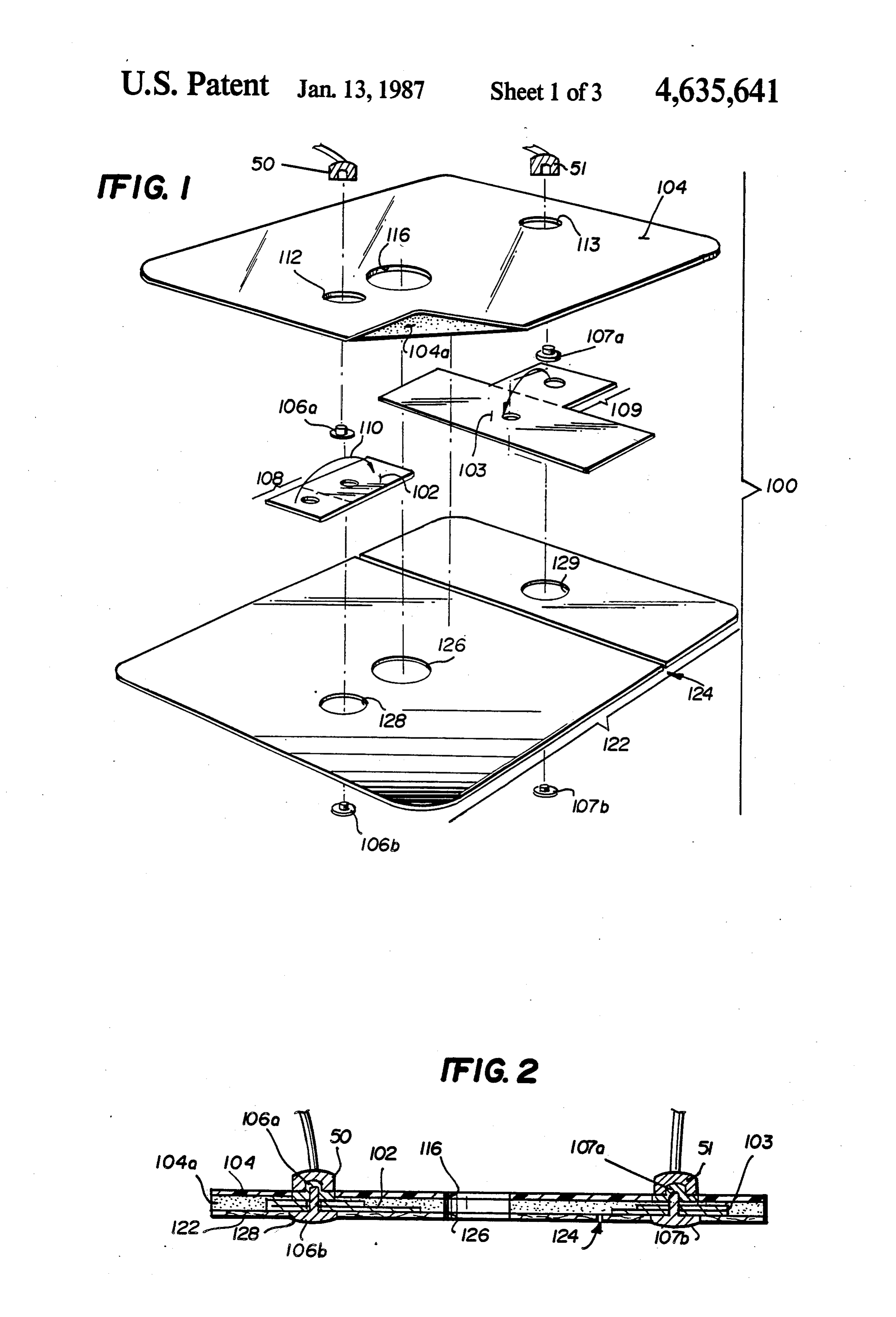
as well as the need to use electrodes of a correct size. Electrical snap-on connection terminals are prefera The requirements for correct placement and correct bly affixed to each conductive patch and extend back size become even more important for electrical signals wards through a further aperture in the insulating sheet that are monophasic or asymmetrical in shape. Two or so as to permit ready electrical connection of a suitable more electrodes of the same or varying sizes are individ 25 electrical lead from an electrical signal generator or ually placed on the patient undergoing some form of other conventional treatment/diagnostic apparatus. electrotherapy or diagnostic procedure. In many cases, The conductive patches of the assembly are preferably optimum results are not obtained because the electrodes flexible and may be formed from thin metal foil patches are not placed on the subject in the correct fashion. pre-laminated to their own thin insulating coating so as It is often necessary to establish a localized electrical 30 to provide added structural strength and to facilitate contact with the external body surface of a living sub adhesion to the adhesive-backed insulating patch. ject. Such contact is typically achieved by the use of These as well as other objects and advantages of the electrically conductive electrodes having extended sur invention will be better appreicated by carefully read face areas placed in electrical contact with a desired ing the following detailed description of the presently portion of an external body surface through an interme 35 preferred exemplary embodiments of this invention diate electrode gel, liquid or other preparation designed taken in conjunction with the accompanying drawings. to ensure good and continuous electrical contact be tween the living body surface and the conductive elec BRIEF DESCRIPTION OF THE DRAWINGS trode surface. Such electrical connections to living FIG. 1 is an exploded perspective view of the various subjects are now commonly required for therapeutic 40 components used in an exemplary embodiment of the and diagnostic applications in both medical and veteri adhesively applied multi-element electrode of this in nary usage. For example, electro-therapeutic stimula vention;
tion has now been recognized to promote the healing of FIG. 2 is a cross-sectional view of the assembled bones and other body tissues and/or to have other ad electrode of FIG. 1;
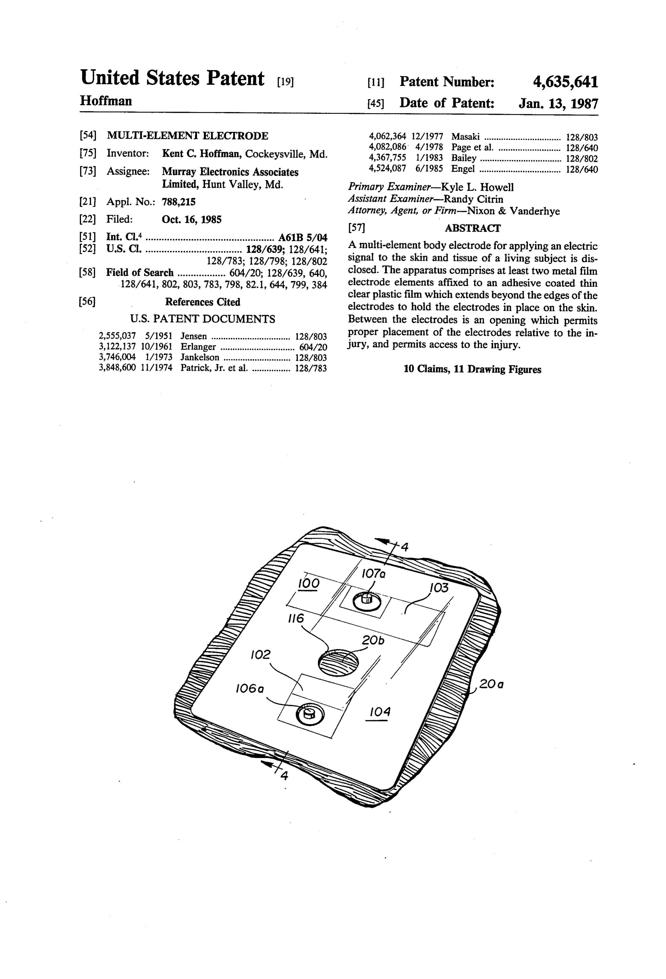
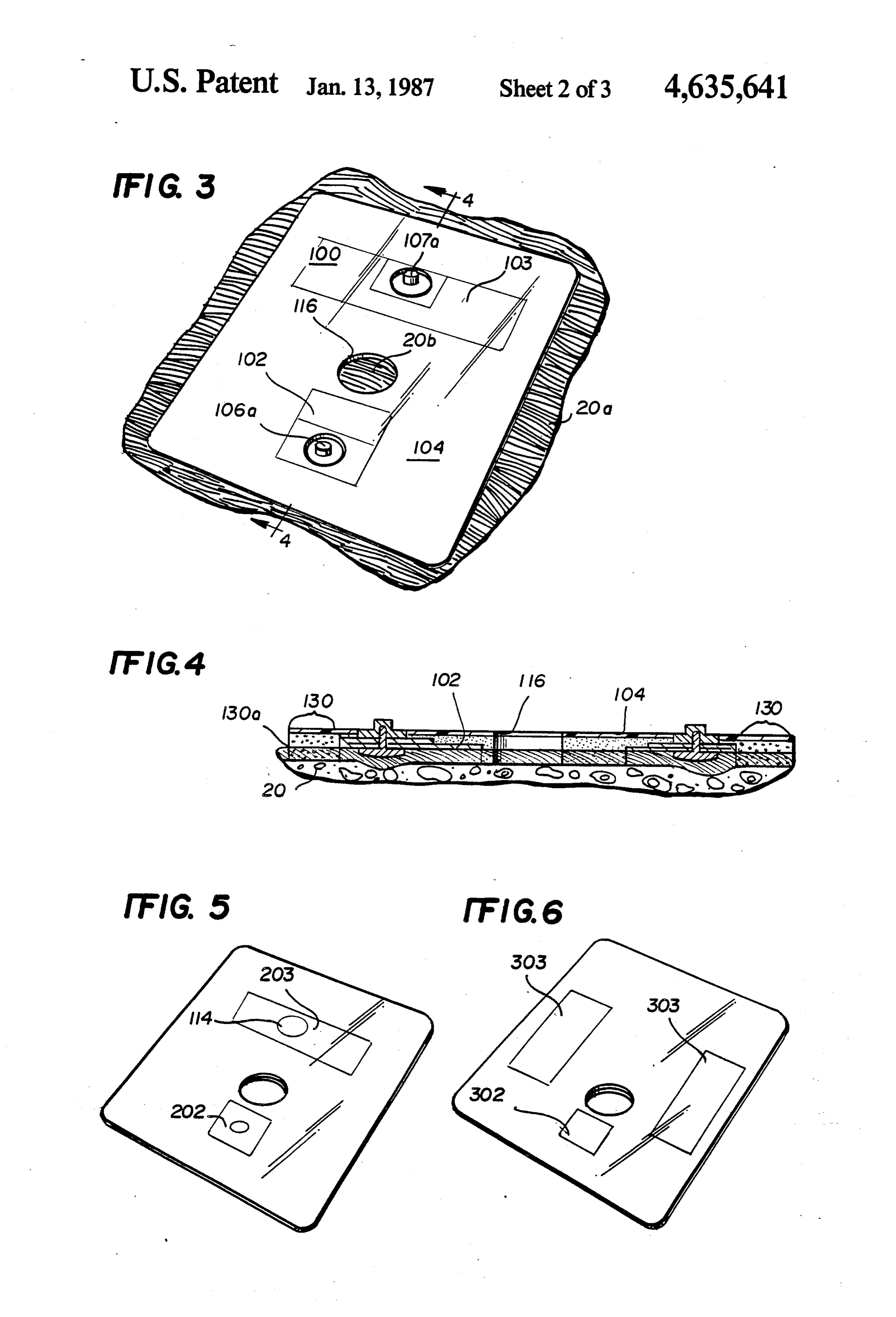
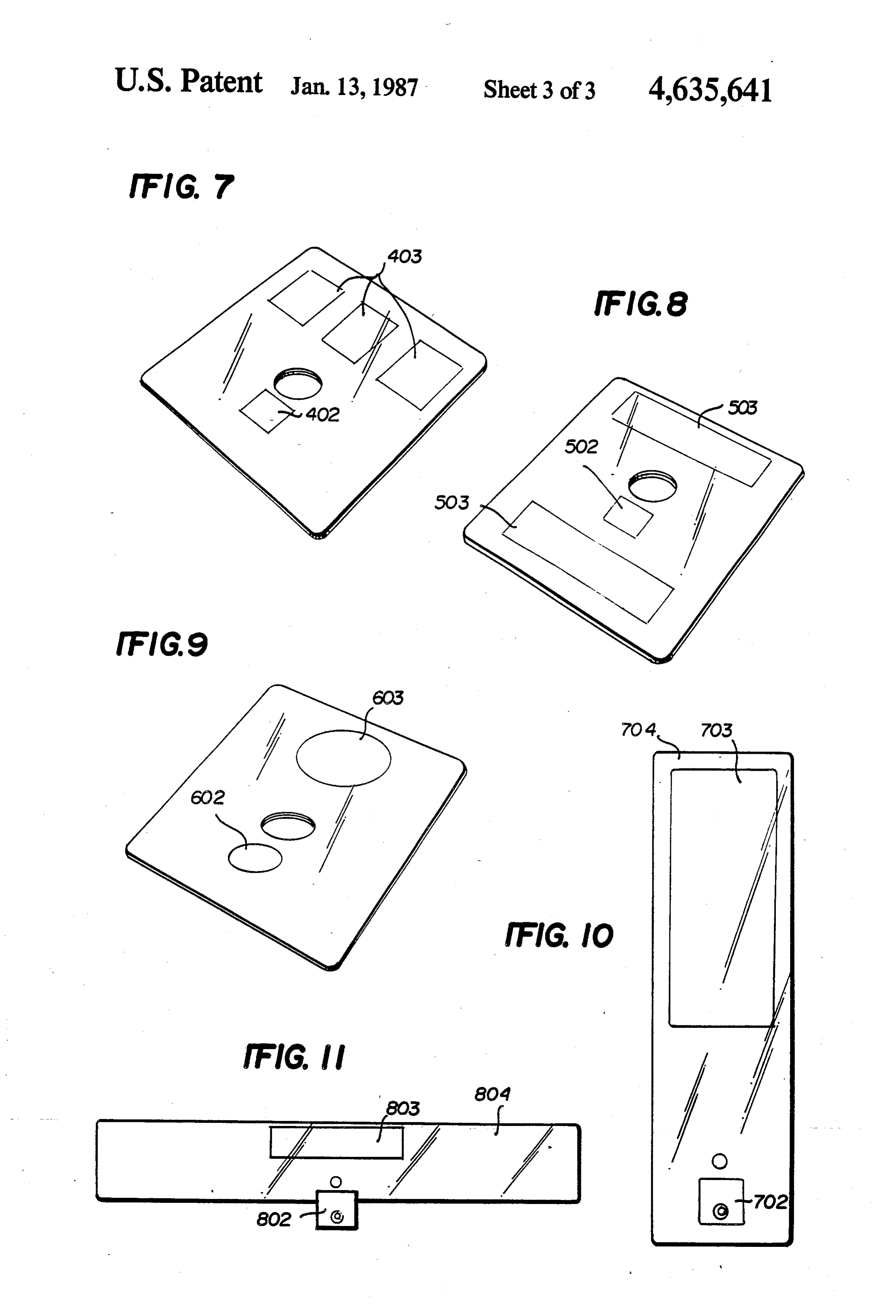
vantageous physiological effects. Many diagnostic tech 45 FIGS. 3 and 4 are perspective and cross-sectional niques (e.g., electrocardiograms) also require electrical views of the FIGS. 1 and 2 embodiment in place with connections to body surfaces so as to monitor electrical the external body surface of a living subject; body surface potentials. FIGS. 5-9 are perspective views of other exemplary U.S. Pat. No. 3,848,608 discloses a cutaneous stimula embodiments of the invention, and tor which includes a plurality of pairs of electrodes and 50 FIGS. 10 and 11 are plan views of two further exem ventilation holes located in a ground plane between plary embodiments of the electrode structure. each adjacent pair of electrodes. This stimulator does not provide an arrangement of electrodes relative to the DETALED DESCRIPTION holes such that therapeutic current density is particu This invention relates to multiple element electrodes larly determined in the vicinity of the holes. Further the 55 that have predetermined relative sizes and locations arrangement disclosed in this reference does not neces relative to an aperture in a common substrate which is sarily provide electrode location control or easy access applied as a single unit, with the aperture conveniently to the injury being treated. being used to (1) properly locate the electrodes vis-a-vis SUMMARY OF THE INVENTION the desired treatment site and (2) provide access to the treatment site after affixation of the electrode structure.
In brief summary, the exemplary embodiment of this The electrode elements are constructed of a metal foil invention provides two or more spaced-apart conduc or film such as aluminum or a conductive film such as tive patches with an adhesive boundary extending at silver paint or carbon compound paint. These elements least part way about the edges of the patches. The adhe are affixed to an adhesive coated, thin, clear film such as sive boundary may comprise a relatively larger adhe 65 pvc or mylar or are screened on a thin, clear film with sive-backed, flexible insulating sheet patch with the adhesive selectively screened on at the same time. The relatively smaller conductive patches being affixed multi-element electrode is produced with an opening or therewithin at predetermined proper relative locations treatment site window to identify correct placement of
Page 6
the multi-electrode unit over the wound or injury. A pre-laminated to a very thin (e.g., 0.00092) layer of release liner is provided on the back of the electrode. A polyester film (laminated to the top of structure 102 as two element example of this multi-element electrode seen in FIG. 1) so as to provide added structural that is useful for treating small skin wounds or burns is strength and to facilitate adhesive affixation to a larger shown in FIG. 1. A monophasic or asymmetrical wave flexible insulating sheet 104 having a treatment site may be conventionally applied across the two elements location aperture 116 located centrally (but asymetri correctly by use of different size electrical connectors cally of the electrodes so as to be directly over the or snaps that mate with the corresponding wires from a intended treatment site located nearer the smaller thera stimulator. peutic electrode) and having an adhesive coating 104a An important feature of this invention is that one 10 on its lower side (as seen in FIG. 1). The laminated element, identified as the treatment electrode, is main aluminum foil/polyester films 102 and 103 may be cut tained at a fixed and optimum distance from the other from commerically available material (e.g. part No. remote electrode element(s) and at the same time is 1035 from Lam-A-Shield Incorporated, Cleveland, maintained at a close, but fixed optimum distance from Ohio). The presently preferred adhesive-backed patch the injury by means of properly locating the treatment 15 104 is also cut from commerically available material site window over the treatment site. Also typically (e.g. part No. 7350 from 3M Corporation which com important in such situations is the fact that the surface prises a thin (e.g., 0.002 inch) insulating sheet of poly area of the treatment electrode may be smaller than the propylene with a thin (e.g., 0.0008 inch) coating of surface area of the remote electrode(s) and that a fixed acrylic adhesive 104 on one side). size ratio and relative location is maintained between 20 A conventional snap-on type electrical connector electrode elements by use of this multi-element elec comprising mated parts 106a and 106b is attached to a trode. The current density at the injury or treatment site folded-over tab portion 108 of the laminated aluminum is maintained at a correct higher therapeutic level while foil structure 102. Similar parts 107a and 107b are at the current density under the remote electrode(s) is tached to the fold-over tab portion 109 of foil 103. Since lower due to the larger surface area of the remote elec 25 it is folded over (as indicated by arrow 110), a conduc trode(s). As those in the art will appreciate, when a tive aluminum foil surface is exposed on both the top given current level I passes through a tissue/skin elec and bottom of the thus double thickness tab portions trode of a given size or area A, the resulting current 108 and 109 for increased structural support and electri density (e.g., amperes per square centimeter) is a func cal area connection with the snap-on devices 106a and tion of I/A. Thus, for a given current level, the current 30 106b and 107a and 107b. The snap-on connector parts density can be increased by making the electrode of have a connector projection which extends backwardly smaller size or, vice versa, it can be decreased by mak (i.e. upwardly in FIG. 1) through apertures 112 and 113 ing the electrode of larger size. And, as will also be respectively in the insulating patch 104 so as to be appreciated, the distance of a given tissue mass from an readily available for snap-on electrical connection to electrode (and its relative location with respect to the 35 lead wires 50 and 51.
anode-cathode current path) will also affect the actual The flexible electrode assembly of FIGS. 1-2 also current density through the tissue mass (e.g., a wound). includes a releasable liner layer 122 which is normally in In this fashion, the relative sizes and placements of place covering the otherwise exposed portions of the anode and cathode electrodes can be used to determine adhesive surface 104a until the intended time of usage. the effective current density through a wound. 40 Typically, the release liner 122 will include a break 124 Typically, for repair of bone fractures, an electrode so that the entire assembly may be slightly bent at the 103 of relatively large area as shown in FIG. 1, is uti break to gain finger access to a free edge of the releas lized as an anode while a relatively smaller electrode able liner 122 and thus facilitate its strippage from the 102 is applied relatively closer to a desired treatment adhesive layer 104a and ready the assembly for adhe site marker hole 116 (so as to provide an increased phys 45 sive affixation to the desired body surface area. iologically significant electrical current density there Release liner 122 is shown as including apertures 126, about) as a cathode electrode, and connected to the 128 and 129. Apertures 128 and 129 typically occurs signal source (not shown) by lead wire 50. Electrical because the liner 122 already may be in place when signals are then conventionally applied to the electrodes aperture 116 is cut during manufacturing processes and so as to achieve desired treatment effects. 50 apertures 128 and 129 permit the assembly of snap-on It should be noted that in some medical applications connectors while the release liner 122 remains in place the smaller electrode 102 is the anode, and thus the thus protecting the adhesive layer 104a during manufac electrode 103 is the cathode. Furthermore, some signal turing processes. However it will be appreciated that sources e.g. transcutaneous nerve stimulators (TENS), such apertures are not required since the release liner supply biphasic signals to the electrodes, i.e. alternating 55 122 is typically removed before the remainder of the current or waveforms with both positive and negative electrode assembly shown in FIGS. 1-2 is adhesively components. The present invention can be used with a affixed to a desired body surface site and used. biphasic signal having the smaller electrode 102 rela FIG. 3 depicts the electrodes of FIGS. 1-2 with the tively close to the treatment site and the larger elec releasable liner 122 removed and the remainder of the trode 103 at a more remote location. This arrangement 60 assembly adhesively secured in place to a desired exter insures a higher density at the treatment site and a nal body surface 20a of a living subject. Typically, the lower, non-biologically stimulative, signal at the larger treatment site 20a should be clean and the connector electrode 103. end of cables 50 and 51 may be snapped onto the snap Multi-element electrode 100 is shown in detail at connectors 106a and 107a to installation of the electrode FIGS. 1 and 2. Conductive metal foils 102 and 103 65 patches onto the treatment site. Once the protective constitute the active electrode surfaces. In the exem releasable liner 122 has been removed so as to expose a plary embodiment, foils 102 and 103 are each actually a boundary 130 of adhesive 104a, the assembly is posi very thin (e.g., 0.00035 inch) layer of aluminum foil tioned with the treatment aperture 116 over the injury
Page 7
site 20b and pressed firmly thereto so as to assure a good the novel features and advantages of this invention. The adhesive bond. As shown in the cross-sectional view of following claims are intended to cover all such varia FIG. 4, the boundary areas 130 will include an adhe tions and modifications.
sively sealed and occluded area 130a which incorpo What is claimed is:
rates any contiguous body hair (or fur) so as to provide 1. A multi-element electrode for making electrical a substantially impervious seal between the external contact to the body surface of a living subject, said surface of living body 20 and the periphery of the con electrode comprising:
ductive electrodes 102 and 103. a first conductive patch having a first area and an As shown in FIG. 5 (having electrodes 202, 203), an electrical connection thereto; electrode patch e.g. 203 can have an aperture 114 ex 10 a second conductive patch having a second area and tending therethrough for receiving an electrode gel an electrical connection thereto; preparation material in the space located between the an adhesive backed-flexible insulating sheet extend electrode patch and the skin surface, after the electrode ing at least part way about the edges of said con patch is adhesively affixed to the skin. ductive patches which are positioned at predeter It should be understood that the present invention 15 mined relative locations on said sheet; and may incorporate more than two electrodes, that is a said adhesive-backed flexible insulating sheet having treatment electrode and multiple remote electrodes (see a treatment location and access aperture extending FIGS. 6-8). Further, the electrodes may be arranged in therethrough at a predetermined asymmetric loca a variety of ways and may be of various shapes and tion relative to said first and second conductive sizes. (see FIGS. 6-9). As shown in FIGS. 6-11, elec 20 patches.
trodes are denoted by numerals 302,303; 402, 403; 502, 2. A multi-element electrode as in claim 1 wherein
lating substrate is generally shown by the out or most said conductive patches are affixed on one adhesive boundary lines and is denoted by reference numerals coated side of said sheet, and further including a 704 and 804 in FIGS. 10 and 11 respectively. 25 release liner releasably attached to and covering When the electrode structure is to be used on horses, the otherwise remaining exposed adhesive-backing it has been experimentally determined that the border of said sheet prior to its intended usage. area 130 of adhesive available for affixation should 3. A multi-element electrode as in claim 1 wherein probably be at least about 0.75 inch wide to insure good said first patch is a treatment cathode electrode and said adhesive affixation. FIG. 11 depicts an alternate em 30 second patch is an anode electrode wherein said treat bodiment without a continuous adhesive border. ment electrode has a smaller surface area than said As should be appreciated, other patch shapes may anode electrode and wherein said treatment electrode is utilize the principles of this invention and, for example, positioned more closely to said treatment aperture. an elongated rectangular patch is depicted in FIG. 10. 4. A multi-element electrode as in claim 2 wherein Similarly, for some applications it may not be necessary 35 said electrical connections each comprise an electrical or even desirable to have a completely continuous adhe snap-on terminal affixed to one of said conductive sive border about the conductive patches. Accordingly, patches and extending through further apertures in said in such cases, the adhesive-backed flexible insulating sheet towards the other side of said sheet. patch 104 may have a considerably different size and 5. A multi-element electrode as in claim 4 wherein shape from that of the conductive patches as is, for said conductive patches comprise metal foil patches example, depicted at FIG. 11. It will also be appreciated prelaminated with an insulating coating on the side that the adhesive backing might in some cases be ap affixed to said sheet and each patch having a doubled plied directly to the periphery or other desired portions back tab area at which said terminal is affixed with of each conductive electrode structure itself. Each con electrical connections being effected to both the ex ductive patch may also be formed by printing, painting 45 posed top and bottom metal foil surfaces in the double or otherwise placing conductive ink on a suitable sub thickness tab area.
strate. However, in the present exemplary embodi 6. A multi-element electrode as in claim 1 wherein at ments, aluminum foil is preferred (e.g., it is conceivable least one patch has at least one gel application aperture that the ions which make an ink conductive might, over extending therethrough.
time, migrate under influence of the electrical treatment 50 7. A multi-element electrode for therapeutic or diag fields away from the printed ink itself thus deteriorating nostic applications in medical or veterinary use which the overall electrode function). may be adhesively affixed to the external body surface In the present exemplary embodiment the conductive of a subject, said electrode comprising: patch 103 may be approximately 3 inches by 1 inch and a plurality of conductive patches for transferring the treatment electrode 102 about one inch square, 55 electrical signals to/from the subject; while the insulating patch 104 may be approximately an adhesive layer extending at least part way about 5X5 inches in overall dimension. Aperture 116 in the the edges of said conductive patches which are embodiment of FIGS. 1-2 may be approximately 0.688 positioned at predetermined relative locations on inch diameter. said layer for holding said conductive patches at It will be understood that the electrode apparatus and predetermined relative locations and in place on method described may also be utilized to achieve con the body surface of a subject; ductive coupling to the external skin surfaces of human at least one treatment location and access aperture subjects as well as animals. being provided in said adhesive layer at a predeter Although this invention has been above-described mined location relative to said electrodes which only with respect to a few presently preferred exem 65 defines the proper location of treatment area and plary embodiments, those skilled in the art will recog which thus facilitates proper placement over an nize that many variations and modifications may be injury or other treatment site and for access to the made in these embodiments while yet retaining many of site; and
Page 8
a releasable liner protectively covering the otherwise said metal foil and insulator patches having aligned exposed adhesive surface of said adhesive layer apertures therethrough;
until the liner is removed to permit affixation to said metal foil patches being disposed on and within said body surface. the adhesively-coated side of said insulator patch at 8. A multi-element as in claim 7 wherein each patch predetermined locations relative to said treatment has a gel aperture extending therethrough to facilitate aperture so that there is a predetermined current surface application of electrode preparation material density at the injury site when the treatment loca through each gel aperture.
tion and access aperture are disposed in a corre sponding predetermined relative location thereat.
9. A multi-element as in claim 7 or 8 wherein; O 10. A multi-element as in claim 9 further comprising said conductive patches each comprise a metal foil a snap-on electrical connector terminal affixed to each patch; of said metal foil patches and extending back through an said adhesive layer comprises an adhesive-backed, aperture in said insulator patch for access through the flexible insulator patch having an area larger than other side thereof. sk k k the combined area of said conductive patches; 15
Provenance
- Collection
- Cited prior art
- Original PDF
- patentimages.storage.googleapis.com →
- Filed
- 1985-10-16
- Pages
- 8
- Method
- pdftotext (the PDF's own text layer) + pdftoppm 300dpi page scans
- Source
- Google Patents bibliographic record
- Granted
- 1987-01-13
- Inventors
- Kent C. Hoffman; Murray Electronics Associates LP
- Transcribed from
- patentimages.storage.googleapis.com →