patent · US4595477
Electrolysis cell
17 June 1986
Page 1 — bibliographic record
United States Patent (19) 11 Patent Number: 4,595,477 Detournay et al. 45) Date of Patent: Jun. 17, 1986 54 ELECTROLYSIS CELL 4,152,225 5/1979 Woodward, Jr. et al. ........... 204/98
75 Inventors: Jean-Paul Detournay, Franiere; 4,229,277 10/1980 Specht ..... ... 204/252 Emile Cabaraux, Brussels, both of 4,278,523 7/1981 Byrd et al... ... 204/252 Belgium 4.325217 5/1982 Byrd et al... 204/252
73) Assignee: Solvay & Cie, Brussels, Belgium
FOREIGN PATENT DOCUMENTS
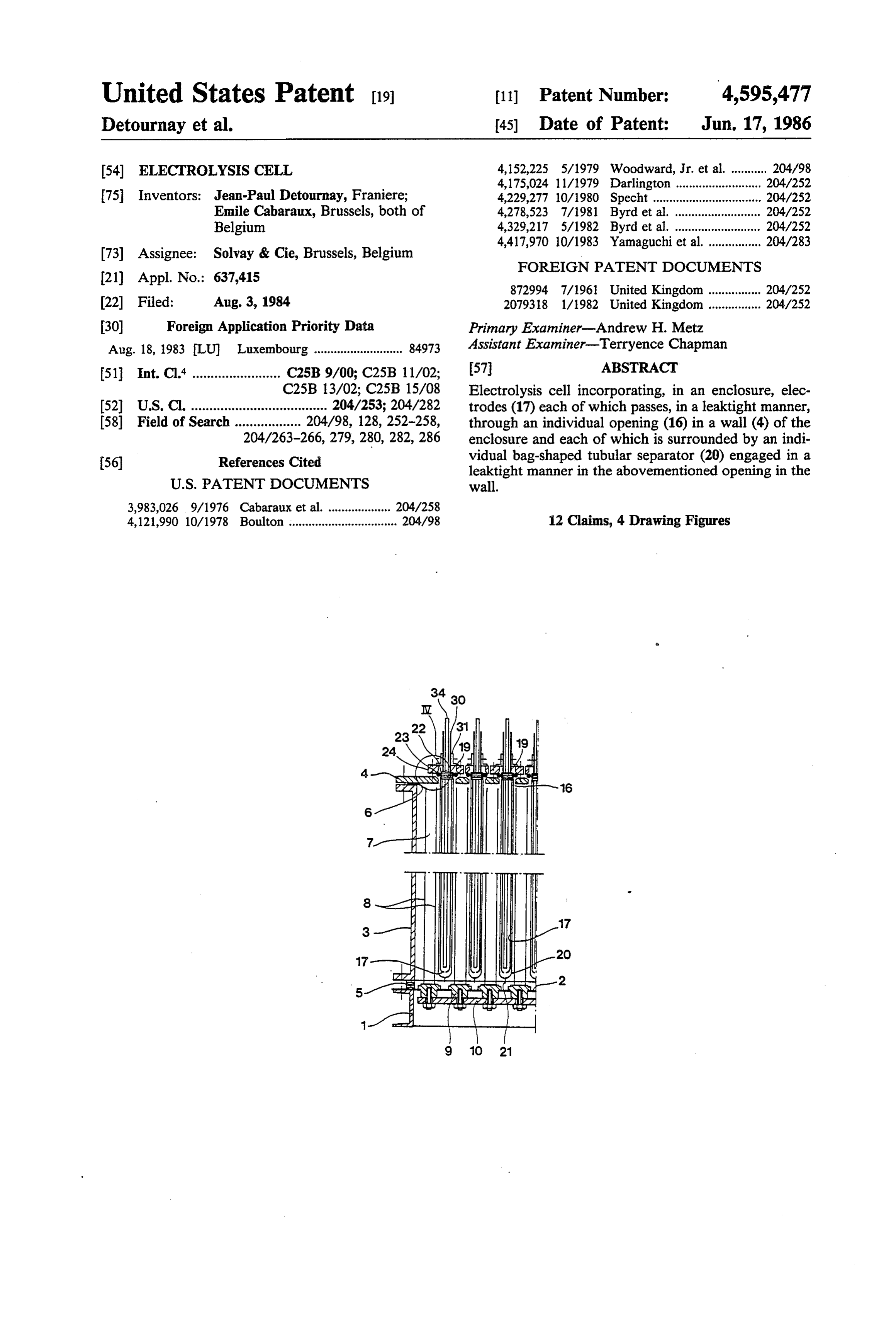
22 Filed: Aug. 3, 1984 2079318 1/1982 United Kingdom ................ 204/252 30 Foreign Application Priority Data Primary Examiner-Andrew H. Metz Aug. 18, 1983 LU Luxembourg ........................... 84973 Assistant Examiner-Terryence Chapman 51 Int. Cl. ........................ C25B 9/00; C25B 11/02; 57 ABSTRACT C25B 13/02; C25B 15/08 Electrolysis cell incorporating, in an enclosure, elec 52 U.S. Cl. ..................................... 204/253; 204/282 trodes (17) each of which passes, in a leaktight manner, 58) Field of Search .................. 204/98, 128, 252-258, through an individual opening (16) in a wall (4) of the 204/263-266, 279, 280, 282,286 enclosure and each of which is surrounded by an indi 56 References Cited vidual bag-shaped tubular separator (20) engaged in a leaktight manner in the abovementioned opening in the
4,121,990 10/1978 Boulton ................................. 204/98 12 Claims, 4 Drawing Figures
s SSS
NSANS.
Page 2
Drawing sheet — no readable text.
Page 3
Drawing sheet — no readable text.
Page 4
Drawing sheet — no readable text.
Page 5
Drawing sheet — no readable text.
Page 6
for the electrolysis of such solutions, they may advanta
ELECTROLYSIS CELL geously be made of titanium or another film-forming metal of the titanium group, carrying an active conduc
The present invention is aimed at improving electrol tive coating incorporating a metal of the platinum ysis cells incorporating, in an enclosure, an alternation 5 group or a compound of a metal of the platinum group. of anodes and cathodes isolated from each other by The function of the separator by which each of the separators, such as permeable diaphragm cells and cells electrodes is surrounded is to isolate the said electrode with a membrane with selective permeability which are from the remaining part of the enclosure. It must be intended for the electrolysis of aqueous solutions of made of a material which can permit an ion stream to sodium chloride. O cross it during the operation of the cell and, for this It relates more particularly to an electrolysis cell purpose, it may be either a diaphragm which is permea incorporating, in an enclosure, electrodes, each of ble to aqueous electrolytes or a selective permeability which passes, in a leaktight manner, through an individ membrane.
ual opening in a wall of the enclosure and each of which Examples of diaphragms which may be employed in is surrounded by an individual tubular separator en 15 the cell according to the invention are asbestos dia gaged in a leaktight manner in the abovementioned phragms, such as those described in the U.S. Pat. No. opening in the wall. 1,855,497 (Stuart), British Pat. No. 2,003,182 (Solvay & An electrolysis cell of this type, in which the separa Cie) and U.S. Pat No. 4,204,941 (assigned to Solvay & tors are diaphragms which are permeable to aqueous Cie) and organic polymer diaphragms, such as those electrolytes, is described in Pat. No. GB-A-872,994 20 described in U.S. Pat No. 3,890,417 (assigned to Impe (Veb Farbenfabrik Wolfen). This known cell incorpo rial Chemical Industries Ltd) and in European Pat Nos. rates, in an enclosure, vertical anodes alternating with 7,674 and 37,140 (Solvay & Cie).
tubular cathodes having a perforated metal wall, which A selective permeability membrane is understood to pass at one end through a side wall of the enclosure and be a thin, non-porous membrane incorporating an ion are supported, at their other end, in a slot arranged in 25 exchanger substance. The choice of the material form the opposite side wall of the enclosure. Each tubular ing the membrane and of its ion exchanger substance cathode is wholly encased in a tubular diaphragm will depend on the nature of the electrolytes subjected which extends between the two above-mentioned side to electrolysis and the products which it is intended to walls of the enclosure and is firmly fixed thereto in a obtain. As a general rule, the membrane material is leaktight manner. 30 chosen from among those which are capable of with In the construction of this known cell, it is found to standing the thermal and chemical conditions normally be difficult to ensure effectively a leaktight fixing of the existing in the cell during the electrolysis, the ion ex diaphragm in the abovementioned slot in the enclosure changer substance being chosen from among the sub wall because access to this slot is difficult. stances which exchange anions or substances which The invention overcomes this disadvantage of the 35 exchange cations, depending on the electrolysis opera known cell described above, by providing an electroly tions for which the cell is intended. For example, in the sis cell incorporating electrodes surrounded by individ case of cells intended for the electrolysis of aqueous ual sleeve-shaped separators, in which cell the zones for sodium chloride solutions for the manufacture of chlo leaktight fixing of the separators in an enclosure of the rine, hydrogen and aqueous sodium hydroxide solu cell are all easily accessible. 40 tions, membranes which are highly suitable are cationic The invention consequently relates to an electrolysis membranes of a fluorine-containing polymer, preferably cell incorporating, in an enclosure, electrodes, each of perfluorinated, containing functional cationic groups which passes, in a leaktight manner, through an individ derived from sulphonic acids, carboxylic acids or phos ual opening in a wall of the enclosure and each of which phonic acids, or mixtures of such functional groups. is surrounded by an individual tubular separator en 45 Examples of membranes of this type are those described gaged in a leaktight manner in the abovementioned in British Pat. Nos. 1,497,748 and 1,497,749 (ASAHI opening in the wall; according to the invention, the KASEI KOGYO K.K.), 1,518,387 and 1,522,877 individual tubular separator of each electrode has the (ASAHI GLASS COMPANY Ltd.) and 1,402,920 shape of a bag which completely encloses the electrode (DIAMOND SHAMROCK CORP) and in U.S. Pat. in the enclosure. 50 No. 4,126,588 (assigned to ASAHI GLASS COM In the cell according to the invention, the contour of PANY Ltd.).
the electrodes is not critical, the latter being capable of Membranes which are particularly suitable for this being of any shape which is compatible with the pur application of the cell according to the invention are pose of the cell. Each of the electrodes, for example, those known under the names "NAFION’ (DUPONT may consist of a planar unit metal plate, perforated or 55 DE NEMOURS & Co) and "FLEMION’ (ASAHI solid, or may incorporate a pair of plates or of planar GLASS COMPANY Ltd).
metal grids, arranged facing each other, or a series of According to the invention, the individual tubular elongated sheets arranged successively facing each separator of each electrode is a bag which completely other; they may be tubular electrodes with perforated encloses the electrode in the cell enclosure. For this walls, for example made of metal mesh, with a cross 60 purpose, it is generally shaped as a tube which is closed section which is circular, oval or polygonal, for exam hermetically at one end, while at the other end it is open ple rectangular. They may be either anodes or cathodes to permit the electrode to be inserted therein. of the cell and, in this case, be made of any conductive Thus, in the cell according to the invention, the sepa material suitable for the electrode reaction which is to rators have a finger-like contour, so that each of them take place thereat when the cell is in operation. Thus, in 65 requires only a single leaktight fixing to the enclosure the case of cathodes for the electrolylsis of aqueous wall, access to this fixing being, moreover, easy. sodium chloride solutions, they may be made, for exam In a particular embodiment of the cell according to ple, of mild steel or nickel, while in the case of anodes the invention, each of the electrodes incorporates a pair
Page 7
of plates arranged facing each other in the bag forming for chloride ions in an aqueous solution, for example a the separator, on either side of a rigid insert bar ar mixture of ruthenium oxide and titanium dioxide. The ranged in the abovementioned opening of the wall, and fixing of the anodes 7 in the cell and their supply with a component for the leaktight sealing of the passage of electric current are implemented in the manner de the said electrode and its separator in the opening incor 5 scribed in U.S. Pat. No. 3,983,026 (assigned to SOL porates a pair of pliable ring seals one of which is com VAY & Cie). For this purpose, the two vertical plates 8 pressed between the separator and the insert bar and the of each anode 7 are welded together on a series of cylin other of which is compressed between the separator and drical titanium rods 9 which pass through the bottom the wall. In this embodiment of the invention, both plate 2 in a leaktight manner and are fixed to a rigid leaktight seals may be made of any elastic and inert O plate 10 made of copper or aluminium which rests on materials which are capable of withstanding the chemi fixed supports 11 under the bottom plate 2 and which is cal and thermal environment normally existing in the connected to the positive terminal of a source of direct electrolysis cell during its use; their mechanical strength current, not shown.
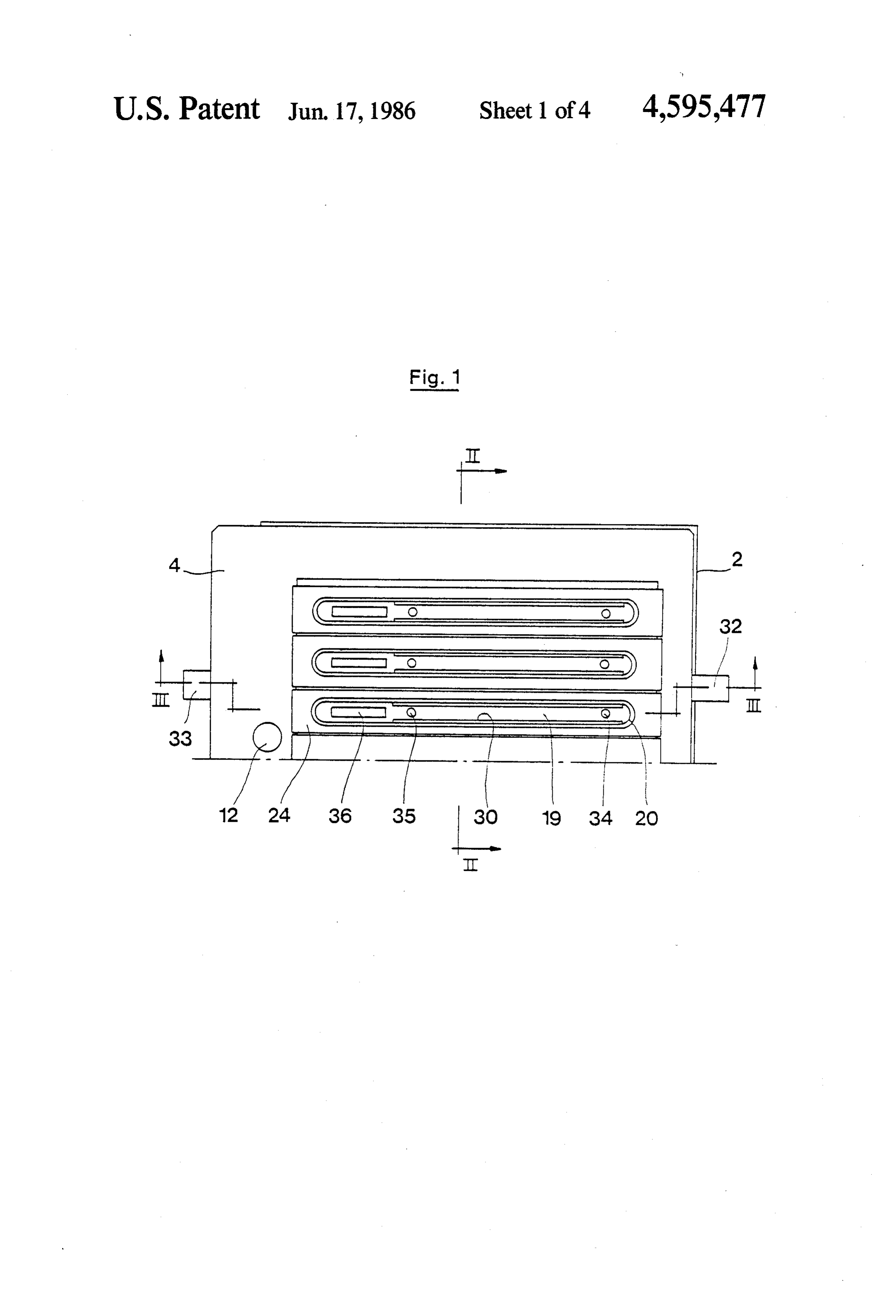
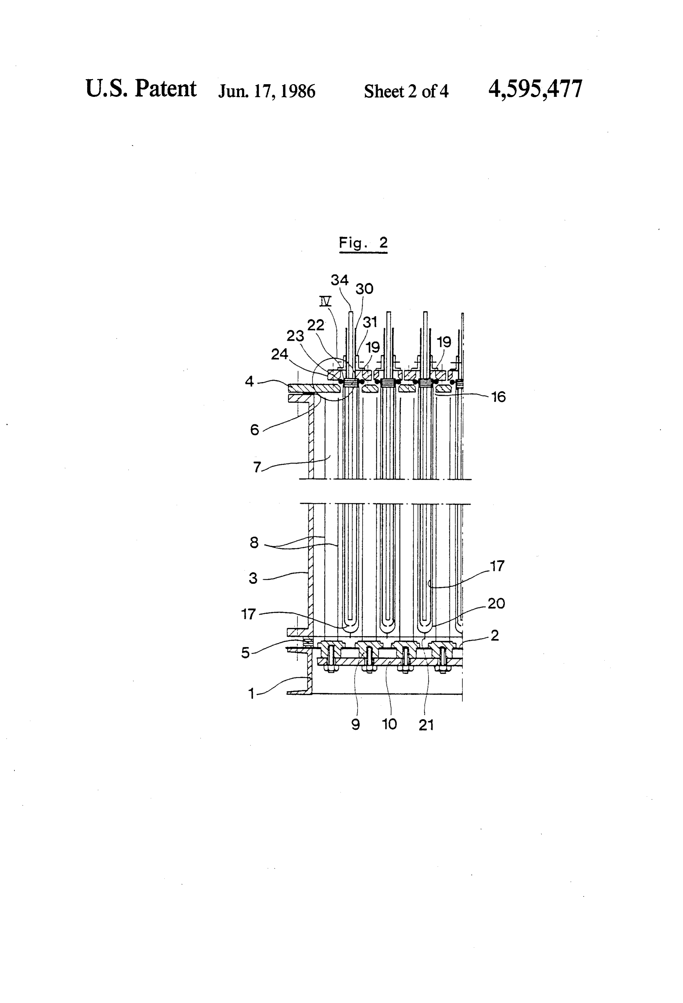
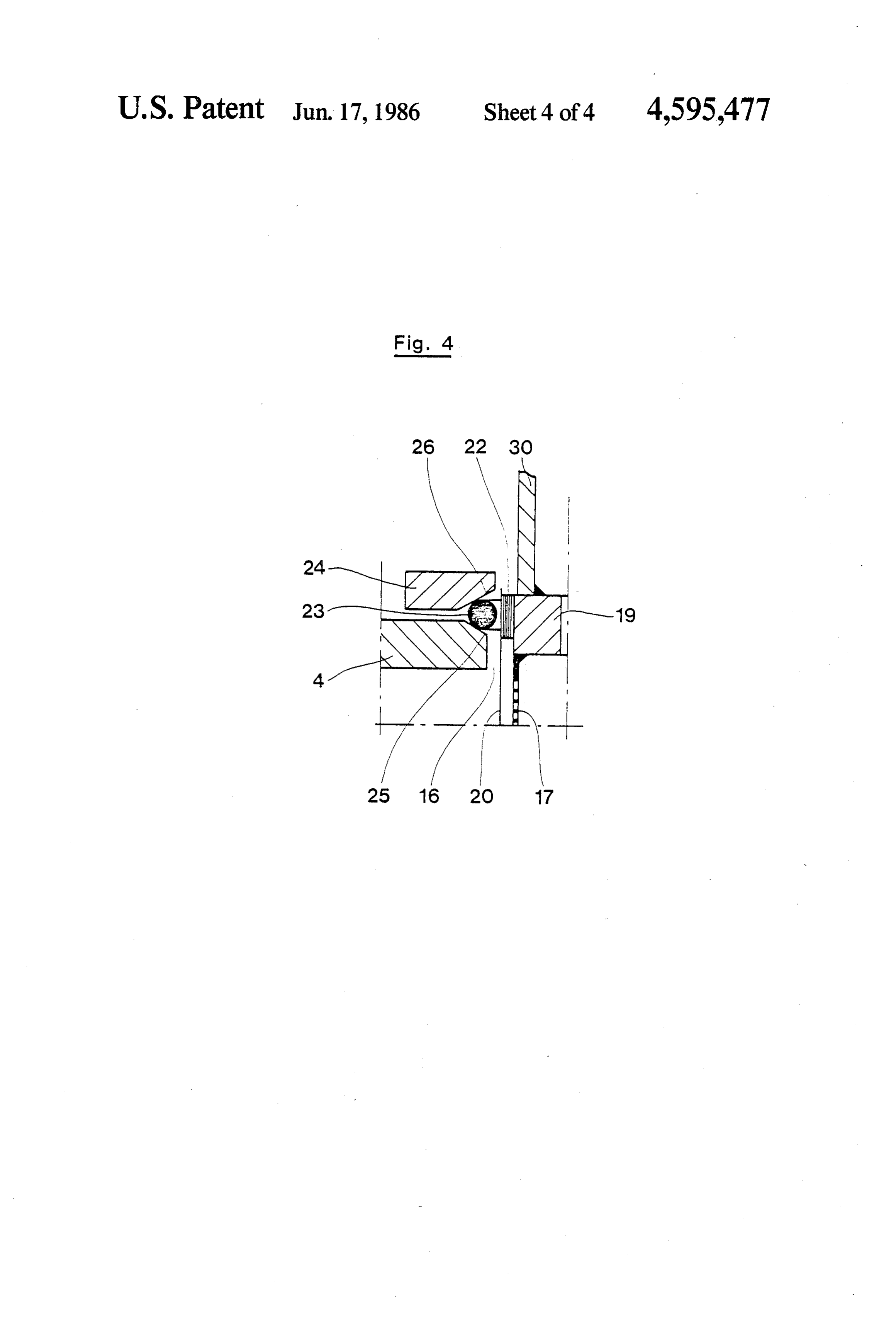
and their elasticity must be sufficient to enable them to The cover 4 is pierced by elongated openings 16 withstand the internal pressure in the cell and to ensure 15 (FIGS. 2 and 3), uniformly spaced relative to each effective leaktight sealing of the latter. other, into which are inserted the individual vertical In the embodiment just described the two leaktight cathodes 17. The cathodes 17 are tubular in shape and, seals are preferably arranged facing each other, on ei for this purpose, each of them consists of a nickel grid ther side of the separator, a clamp compressing the which is arranged so as to have two planar vertical outer seal, which preferably has a circular cross-section, 20 lengthwise faces facing the anode plates 8, connected by against the membrane and the wall of the enclosure in curved vertical transverse faces; each grid 17 is sus the opening of the latter. pended from a horizontal insert bar 19, also made of In the cell according to the particular embodiment nickel.
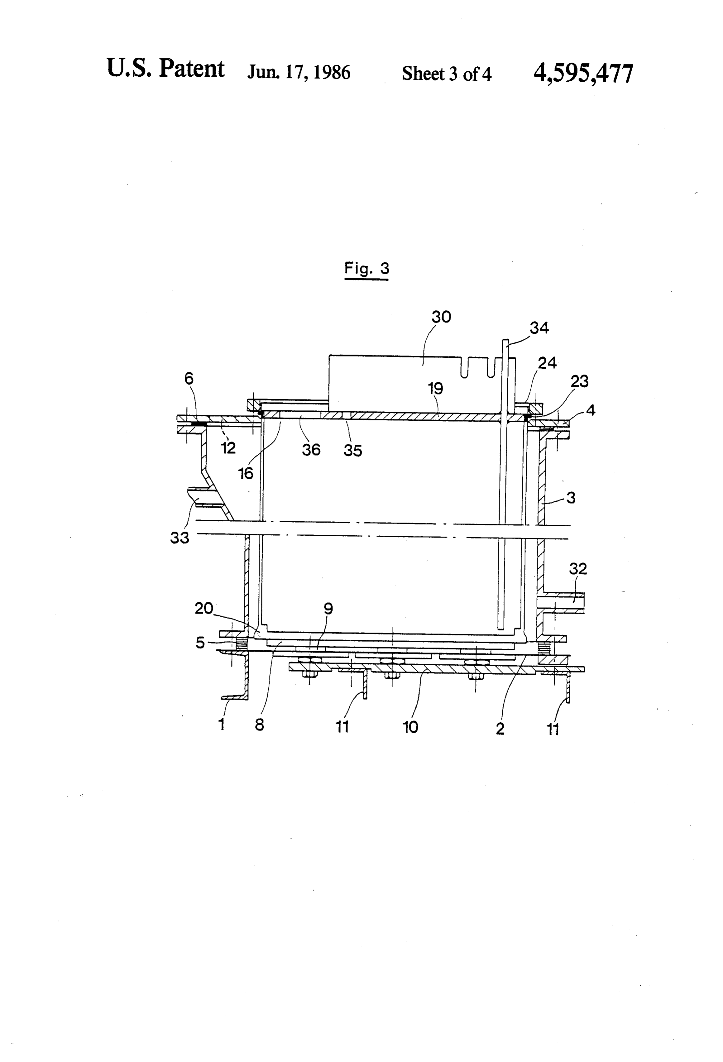
just described it is easy to connect the electrodes in Each cathode 17 is wholly surrounded with a cationic parallel to a busbar arranged outside the enclosure, by 25 membrane 20 as described above, in the shape of a tubu means of electrical conductors integrally fixed respec lar or finger-shaped bag closed at its lower end 21 (FIG. tively to said insert bars of the electrodes. 2).
The invention applies equally to electrolysis cells The leaktight sealing of the passage of each cathode with vertical, horizontal or oblique electrodes. 17 and its membrane 20 in the corresponding opening 16 In the case of a cell with vertical electrodes, the en 30 of the cover 4 is ensured by means of a leaktight sealing closure wall through which the electrodes pass may be member which incorporates (FIG. 4) a first pliable ring a vertical side wall, or the bottom wall of the enclosure, seal 22 arranged around the insert bar 19, between the or an upper horizontal wall of the enclosure. A pre latter and the bag forming the membrane 20, a second ferred cell is one in which this is an upper horizontal pliable ring seal 23 which is arranged around the bag wall, and more especially a removable cover of the 35 forming the membrane 20, at the height of the seal 22, enclosure, from which the electrodes and their respec and a metal ring 24 employed as a clamp and fixed tive tubular separators are then suspended. firmly to the cover 4 by any suitable means, for example Individual features and details of the invention will a nut and bolt assembly, to clamp the two seals 22 and become apparent from the following description of the 23 and the membrane 20 against the insert bar 19 and the attached drawings which show diagrammatically a cover 4, at the periphery of the opening 16. In order to particular embodiment of the cell according to the in guarantee a durable leaktignt sealing, the seal 22 is pref vention. erably given a rectangular cross-section and the seal 23
BRIEF DESCRIPTION OF THE DRAWINGS
a circular cross-section. It is, moreover, especially ad vantageous that the surface 25 of the cover 4 bearing on
FIG. 1 is a plan view of a part of the cell; FIG. 2 is a 45 the seal 23 and the surface 26 of the clamping ring 24 vertical cross-section along the plane II-II of FIG. 1; bearing on the seal 23 have divergent gradients directed FIG. 3 is a vertical cross-section along the plane towards the insert bar 19 (FIG. 4). The seals 22 and 23 must be made of materials which
III-III of FIG. 1;
FIG. 4 shows, on a larger scale, a detail outlined by are capable of withstanding the pressure and the chemi the circle IV in FIG. 2. 50 cal and thermal conditions existing respectively in the In these Figures, the same reference numerals indi cathode chambers 28 and in the anode chamber 29 of cate identical elements. the cell; more particularly, the material chosen for seal The cell shown in the figures is a cell with a selective 22 must be capable of withstanding concentrated aque permeability membrane for the electrolysis of aqueous ous sodium hydroxide solutions, while the material of sodium chloride solutions. It incorporates (FIGS. 2 and 55 seal 23 must be capable of withstanding chlorine and 3) an enclosure placed on a base 1 and consisting of a concentrated aqueous sodium chloride solutions. titanium horizontal bottom plate 2, a casing 3 placed The electrical supply to the cathodes 17 is provided vertically at the periphery of the plate 2 and a cover 4. by means of copper or aluminium bars 30, welded in Pliable ring joints 5 and 6 ensure leaktight sealing be pairs to the insert bars 19 and connected in parallel to a tween the bottom plate 2, the casing 3 and the cover 4. 60 busbar, not shown, joined to the negative terminal of The casing 3 and its cover 4 are made of a material theToabovementioned source of direct current. guarantee correct positioning of the cathodes 17 which withstands chlorine and brines under the normal operating conditions of electrolysis cells. In the enclo in the cell, they may advantageously be firmly fixed to sure, vertical anodes 7 alternate with vertical cathodes the cover 4 through the intermediacy of angle brackets 17. 65 31 fixed to the bars 30 and to the rings 24 (FIG. 2). Each anode 7 is formed by a pair of vertical titanium The casing 3 is equipped (FIGS. 1 and 3) with pipe plates 8, perforated if appropriate, carrying a coating of work 32 for introducing a concentrated, preferably a conductive material with low discharge over-voltage saturated, solution of sodium chloride and pipework 33
Page 8
for withdrawing a dilute solution of sodium chloride; and a second ring seal comprised between said separator the chlorine produced at the anode plates 8 is removed and said wall.
through the orifices 12 in the cover 4. 3. A cell according to claim 2, in which said two seals The insert bar 19 of each cathode 17 is crossed by a are arranged facing each other on opposite sides of said vertical tube 34 for the entry of water or a dilute sodium 5 separator and in which said second ring seal has a circu hydroxide solution (containing, for example, 10% by lar cross section and is compressed between the separa weight of sodium hydroxide) and is pierced by an open tor, a face of said respective opening, which face slopes ing 35 serving for removing a concentrated sodium toward said separator and a rigid ring surrounding said hydroxide solution (containing, for example from 25 to opening and secured to said wall.
40% by weight of sodium hydroxide), produced during 10 4. A cell according to claim3, in which the two plates the electrolysis; the hydrogen formed at the cathodes 17 of said each electrode are firmly fixed to the respective is removed through an orifice 36 in the insert bar 19. insert bar for which in turn is attached to the respective In an advantageous alternative form of the electroly rigid ring.
sis cell which has just been described, with reference to 5. A cell according to claim 3, in which said elec FIGS. 1 to 4, the insert bars 19 consist of a copper or 15 trodes are coupled in parallel to a bushbar arranged aluminum core and a nickel sheath which are assembled outside said enclosure by electrical conductors firmly by the known technique of coextrusion. In this alterna connected respectively to said insert bars of said elec tive form of the invention, the nickel sheath may com trodes.
pletely cover the copper or aluminium core. It is prefer 6. A cell according to claim 1, in which said wall able, however, to employ insert bars 19 in which the 20 comprises an upper horizontal wall of said enclosure nickel sheath does not cover the upper face of the core, and in which said electrodes with their respective sepa in order to facilitate the welding of the bars 30. rators are suspended vertically from said wall. To construct the cell shown in the figures, the anodes 7. A cell according to claim 6, in which said wall is a 7 and the bottom plate 2 are assembled, the casing 3 is removable cover of said enclosure. placed on the bottom plate 2 and the cover 4 is fixed to 25 8. A cell according to claim 6, in which said elec it. Each cathode 17 is fixed separately to its ring 24 by trodes are cathodes and alternate with vertical and means of the angle brackets 31, is inserted into its bag shaped membrane 20, and the seals 22 and 23 are ar parallel anodes in said enclosure. 9. A cell according to claim 8, in which said cell is a ranged around the insert bar 19. The cathodes and their corresponding membranes are then inserted into the 30 cell for the electrolysis of aqueous sodium chloride casing 3 through the openings 16 and the rings 24 are solutions.
firmly fixed to the cover 4 to compress the seals 22 and tor10.is A cell according to claim 1, in which said separa a selectively permeable membrane.
We claim: 11. An electrolysis cell comprising an enclosure hav 1. An electrolysis cell comprising an enclosure hav-35 ing a wall with a plurality of openings, a plurality of electrodes in said enclosure, each of said electrodes ing a wall with a plurality of openings, a plurality of electrodes in said enclosure, each of said electrodes being in line with a respective one of said openings, a passing individually through a respective one of said rigid bar attached to each of said electrodes and re openings, an individual tubular separator surrounding ceived in each respective one of said openings, a tubular each of said electrodes, said separator being in the shape 40 separator surrounding each of said electrodes, said sepa of a bag which wholly encloses the portion of said each rator being in the form of a bag which wholly encloses electrode that is in said enclosure and which has an the portion of the respective electrode that is in said open end portion through which said each electrode is enclosure and having an open end portion to receive inserted and which extends in the respective opening said electrode, said open end portion being disposed in for said each electrode and means for providing a leak- 45 said respective opening and surrounding said rigid bar tight seal between said end portion of said each separa and sealing means for providing a leaktight seal be tor and the respective electrode and between said end tween said end portion of said separator and said rigid portion of said each separator and the portion of said bar and between said end portion of said separator and enclosure wall surrounding said respective opening. a portion of said wall surrounding said respective open 2. A cell according to claim 1, in which each of said 50 ling.
electrodes comprises a pair of plates facing each other 12. A cell according to claim 11, in which said sealing and a rigid bar inserted between said plates and disposed means comprises a pair of pliable rings one of which is in the respective one of said openings through which compressed between said separator and said rigid bar of said each electrode passes, and in which said means the respective electrode and the other of which is com providing a leak-tight seal comprises a first ring seal 55 pressed between saidk wall
and
saidis separator.
compressed between said separator and said insert bar
Provenance
- Collection
- Cited prior art
- Original PDF
- patentimages.storage.googleapis.com →
- Filed
- 1984-08-03
- Pages
- 8
- Method
- pdftotext (the PDF's own text layer) + pdftoppm 300dpi page scans
- Source
- Google Patents bibliographic record
- Granted
- 1986-06-17
- Inventors
- Jean-Paul Detournay; Emile Cabaraux; Solvay SA
- Transcribed from
- patentimages.storage.googleapis.com →