patent · US4148703
Method of electrophoretic purification of enzymes and peptides by means of an adjustable, specialized, geometrically located electrode system
10 April 1979
Page 1 — bibliographic record
United States Patent (19) (11) 4,148,703 Trop et al. 45) Apr. 10, 1979
54 METHOD OF ELECTROPHORETIC operation. The method enables the user to secure a high PURFICATION OF ENZYMES AND purification of enzymes and peptides simultaneously as PEPTIDES BY MEANS OF ANADJUSTABLE, it allows their purification on a large scale, the process SPECIALIZED, GEOMETRICALLY is modularized with interchangeable parts and contains LOCATED ELECTRODE SYSTEM several divergent configurations such as diagonal linear 75 Inventors: Moshe Trop; Joseph Herbst, both of electrodes, point or ball electrodes, parabolic elec Brooklyn, N.Y. trodes, arced electrodes, and other geometrically shaped electrodes. The modularization permits the easy 73) Assignees: Morton Weintraub; Bernard insertion and removal of different geometrically shaped Gendelman, both of Brooklyn, N.Y. electrodes which allow a multifunctional versatile in (21) Appl. No.: 657,232 plementation and application of electrophoresis in the purification of electrically charged biomolecules. The 22 Filed: Feb. 11, 1976 different geometrically shaped electrodes also permit 51) Int. Cl. ...................... G01N 27/26; G01N 27/30 potentially different gradients, thereby enabling differ 52 U.S. Cl. ........................... 204/180 G; 204/180 R; ent particle velocities, finer separations, and continuous 204/299 R electrophoresis, by means of a higher voltage, in a 58 Field of Search ........... 204/180 R, 180 S, 180 G, smaller area, with a decrease in power expenditure. The 204/299, 300 method includes such innovative features as automatic (56) References Cited switching, and repetitive & selective operation of the
divergent geometrically shaped electrode systems. The automatic switching consists of electronic circuits 2,853,448 9/1958 Heiskell, Jr. ......................... 204/299 which alternately select the various electrode systems 3,255,100 6/1966 Raymond ........................ 204/180 G to be turned on and off at a given time independently of 3,384,568 5/1968 Kato et al. ..... ... 204/299 X one another, for a given duration of time, in order to 3,567,611 3/1971 Michel et al. ........................ 204/299 maintain a clearly defined electrical field distribution, or 3,616,457 10/1971 Hjerten et al. ... 204/299 3,773,645 11/1973 Nees et al. ......... ... 204/299 gradient, along the width and length of the gel. The 3,773,648 11/1973 Van Welzen et al. ... 204/299 repetitive & selective operation of the divergent geo 3,788,969 1/1974. De Stefano et al... ... 204/299 metrically shaped electrode systems enable the selection
of the most suitable geometrically shaped electrode system to obtain optimum separation in the purification
Primary Examiner-Arthur C. Prescott of particular electrically charged biomolecules.
The method of electrophoretic purification of enzymes & peptides which is a continuous, modularized, one-step 7 Claims, 16 Drawing Figures
Page 2
Drawing sheet — no readable text.
Page 3
Drawing sheet — no readable text.
Page 4
Drawing sheet — no readable text.
Page 5
Drawing sheet — no readable text.
Page 6
Drawing sheet — no readable text.
Page 7
Drawing sheet — no readable text.
Page 8
METHOD OF ELECTROPHORETC
field or both fields, is in a gradient form alongside the
PURIFICATION OF ENZYMES AND PEPTDES
width of the field applied onto the gel layer. This is accomplished by introducing electrodes, forming the
BY MEANS OF ANADJUSTABLE, SPECIALIZED, respective fields, in such a way that the resistance of the GEOMETRICALLY LOCATED ELECTRODE medium is gradually changed along the width of the SYSTEM field. These changes are adjusted to follow many differ BACKGROUND AND SUMMARY OF THE ent curves such as linear, exponential, hyperbolic, circu INVENTION lar and other shapes, by altering the geometric location and shapes of these electrodes, the theory being that a
An improvement in the method of purifying enzymes O greater rate of change in the field yields a finer separa and peptides that is continuous, one step in operation, tion of particles. A typical configuration of the linear and modularized, which utilizes polyacrylamide gel as a gradient can be achieved by placing electrodes diago medium for continuous separation but does not make nally alongside the gel and using the variations in diago use of a flowing of the buffer through the gel. The nal to control the slope of the gradient. The exponential method is continuous, in that the flow of the stream of 15 crude enzymes and peptides is not interrupted during gradient linear but may be achieved in the same manner as the using an exponential curve in the electrodes.
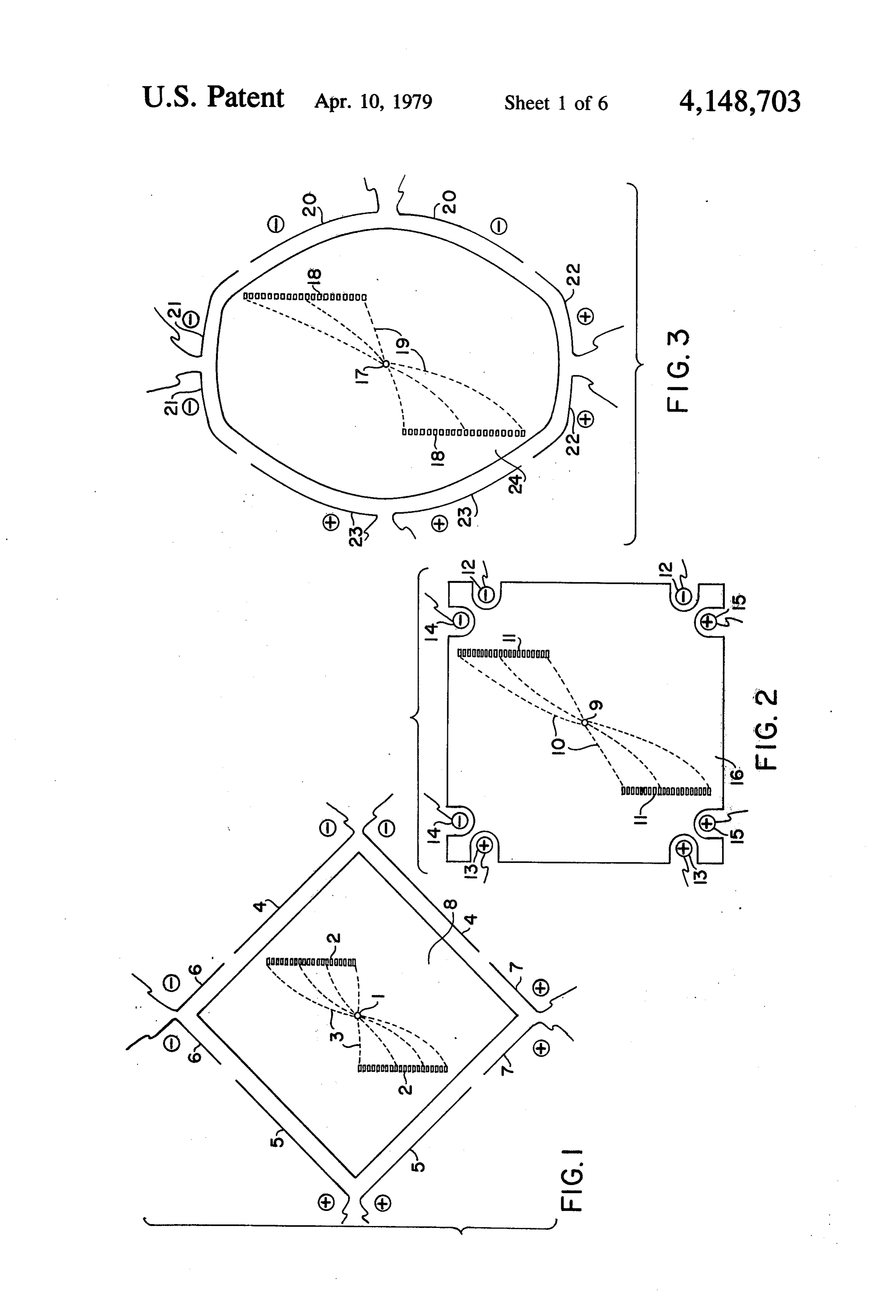
any stage of the operation. The method is one-step in The point or ball electrodes in an exponential system the operation of purification as the enzymes and pep consist of electrodes in small circles of buffers, one for tides, from the time they are fed into the gel, undergo a positive and one for negative. These electrodes when process of purification which requires no additional 20 placed as indicated (in FIG. 2) produce a field which steps of purification. The electrophoresis on the poly has an exponential effect on the particle accelerations acrylamide gel results in high purification as the poly thereby yielding better particle separation. Other varia acrylamide is one unified piece of gel which purifies tions such as concave and convex hyperbolic curves higher than any other substance because it provides a have proven to yield beneficial results. The enzymatic high molecular sieving resolution. The "Adjustable 25 preparation mixture is introduced into the gel continu Specialized Geometrically Located Electrode System' ously by a very slow constant flow, through a thin results in purification of enzymes and peptides on a tubing into a hole crossing the thickness of the gel, large scale, for the different geometrically shaped elec during the application of the electrical fields. The verti trodes provide different pathways for each different cal electrical field is the "separator' of proteins accord enzyme and peptide existing in the crudely applied 30 ing to their mobility in the field on account of the net mixture thereby enabling the separation, elution, and charge, molecular dimension, and molecular configura collection of typical enzymes and peptides, though as tion, by applying upon them a vertical vector (A). The many as one hundred different enzymes and peptides horizontal electrical field applies a vector (B) and are caused to flow from the crude protein mixture causes the proteins to move horizontally. The proteins through the gel at the same time. The modularization of 35 pass through the gel via a series of tiny holes across the the interchangeable parts of the electrode system, thickness of the gel, eluted by the flowing buffer which which include such geometrically different shapes as runs during the operation. The gradient is the factor diagonal linear electrodes, arced electrodes, parabolic which enables the faster fractions to emerge sooner and electrodes, point and ball electrodes, and other shapes, closer to the application point than the slower ones. An create a diversity of field gradients by causing many ambient temperature is maintained at any degree needed different particle vectors, and permit a multifunctional by circulation of coolant around a vertical plate from a versatile implementation and application of electropho refrigerated bath, permitting preparative separations for resis in the purification of the enzymes and peptides. heat labile substances such as enzymes. A combinational The automatic switching system of the electrodes, system is used to yield better separation. Each band that which last from 1/100th of a second to 10 seconds, and 45 is separated is run through higher voltage, an electrode the on and off repetitive selectivity of the electrodes, separation having better differentiation to obtain a finer enable the prevention of the electrode system's interfer yield. The advantage is that a smaller system is required ence on one another, and enable the avoidance of short for a greater batch of input. Another advantage is that circuits, thereby providing the creation of required less heat is dissipated by the system due to the lower potential vectors. The "Adjustable, Specialized, Geo 50 voltage required for a smaller system. metrically Located Electrode System' containing the innovative features of modularization of electrode sys BRIEF DESCRIPTION OF DRAWINGS tems, automatic switching, repetitive and selective op FIG.1 represents a view of the cell using diagonal erations of the divergent geometrically shaped elec linear electrodes.
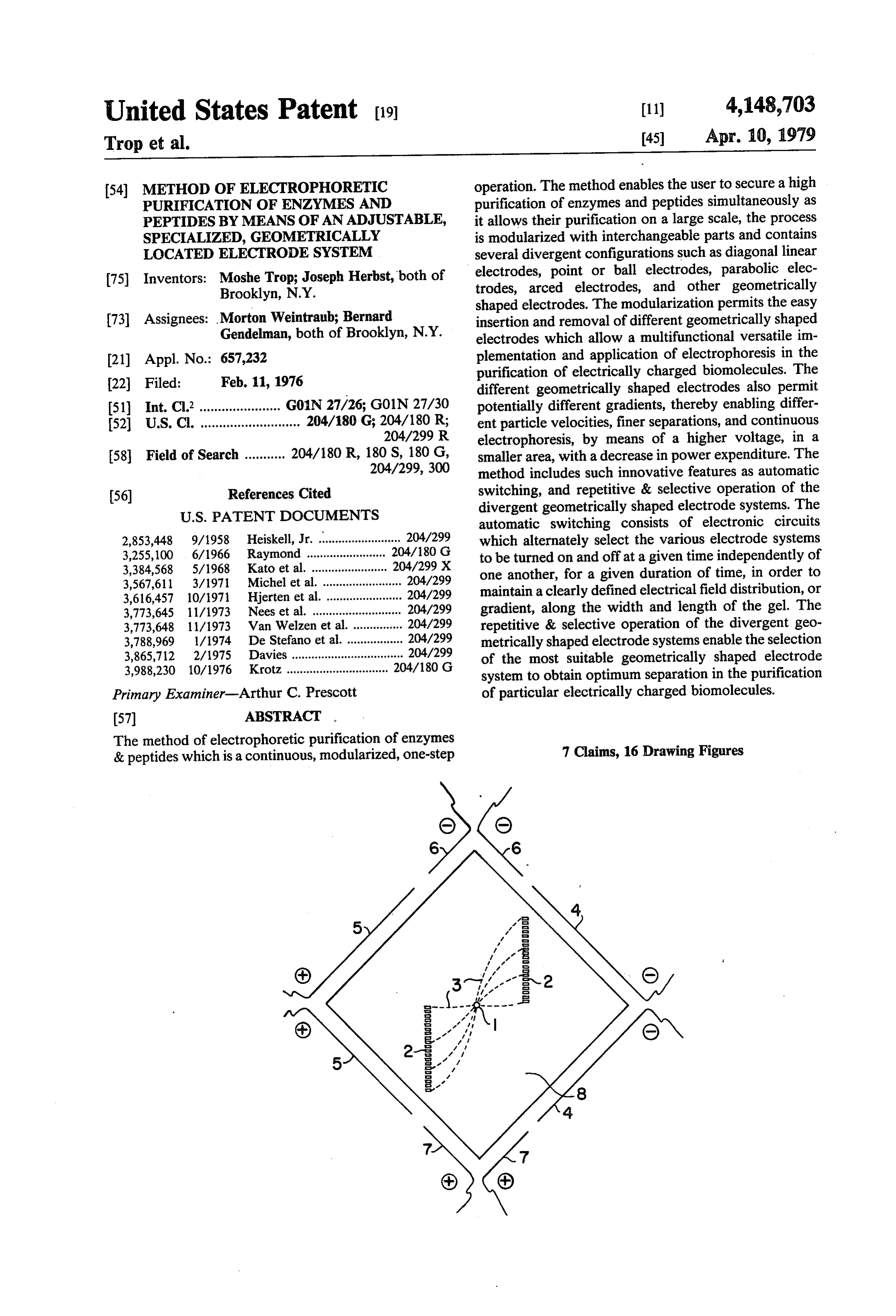
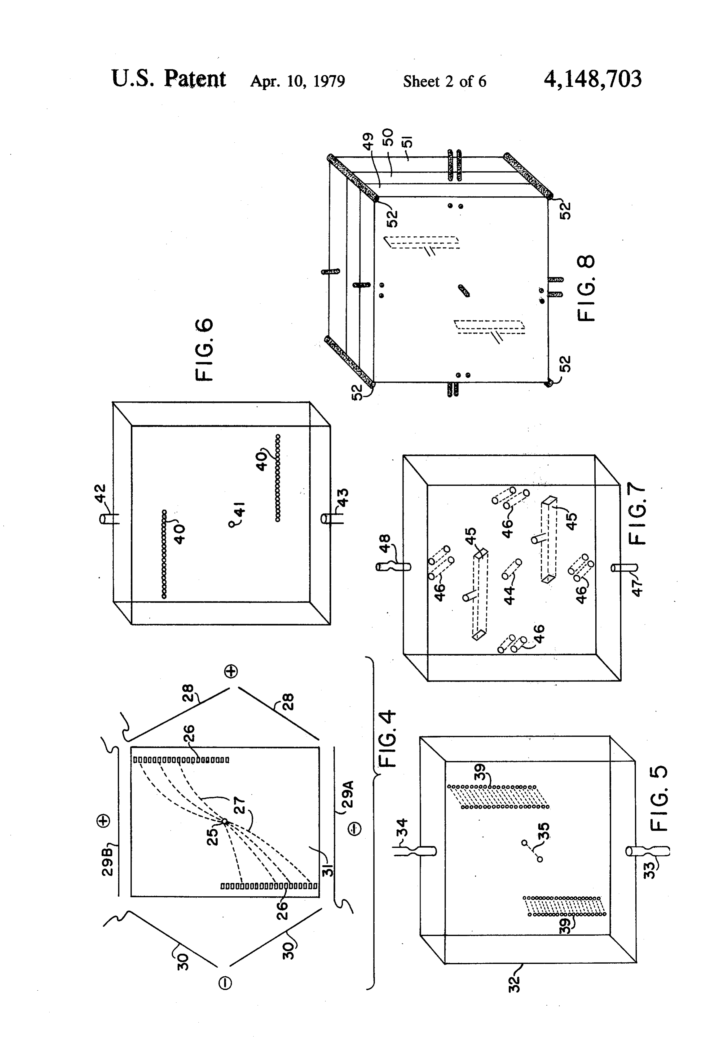
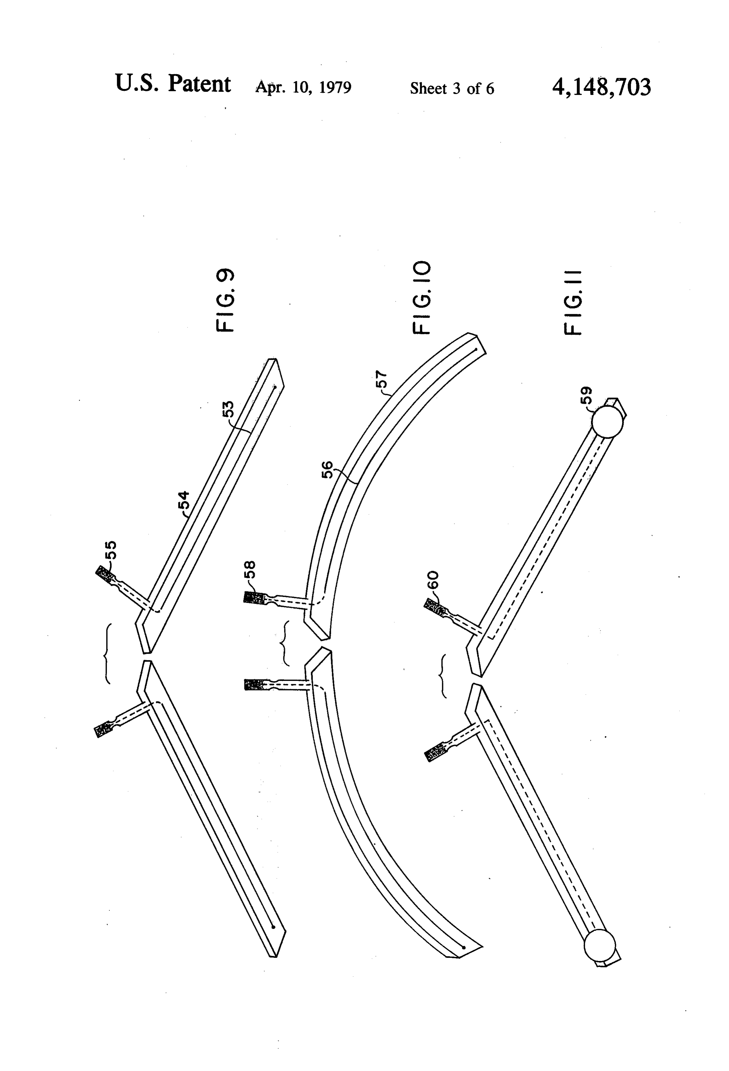
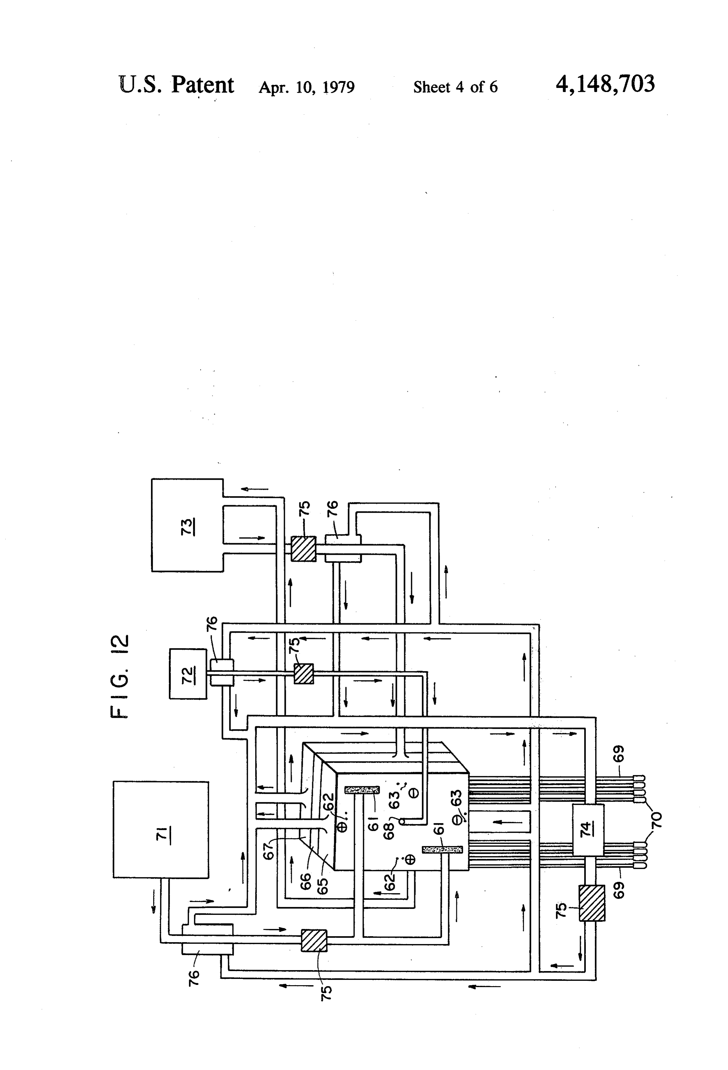
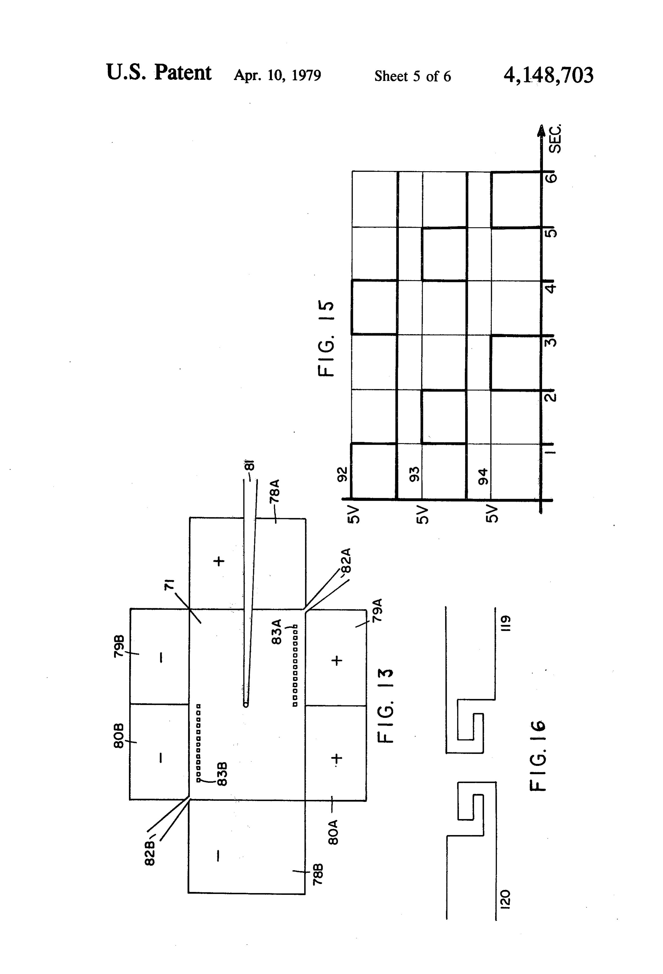
trode systems, and the divergent geometrically shaped 55 FIG. 2 shows a view of the cell with ball electrodes. electrode systems, have not been used in the past or FIG. 3 depicts the cell with parabolic electrodes. present methods of electrophoresis. FIG. 4 depicts the cell with parallel linear electrodes. The method allows a high purification simulta FIGS. 5, 6, 7 and 8 illustrate the three chambers com neously as it allows purification on a large scale, dual bined to form an electrophoresis cell. factors which do not exist together under present meth FIGS. 9, 10 and 11 depict electrode nodules. ods of electrophoresis. The method conceives a separa FIG. 12 illustrates a flow system for the process of tion in a rectangular thin gel placed between the sepa the invention.
rate independent fields perpendicular to each other. FIG. 13 is a block drawing of the nodularized classes The two electric streams are not operated simulta and subclasses.
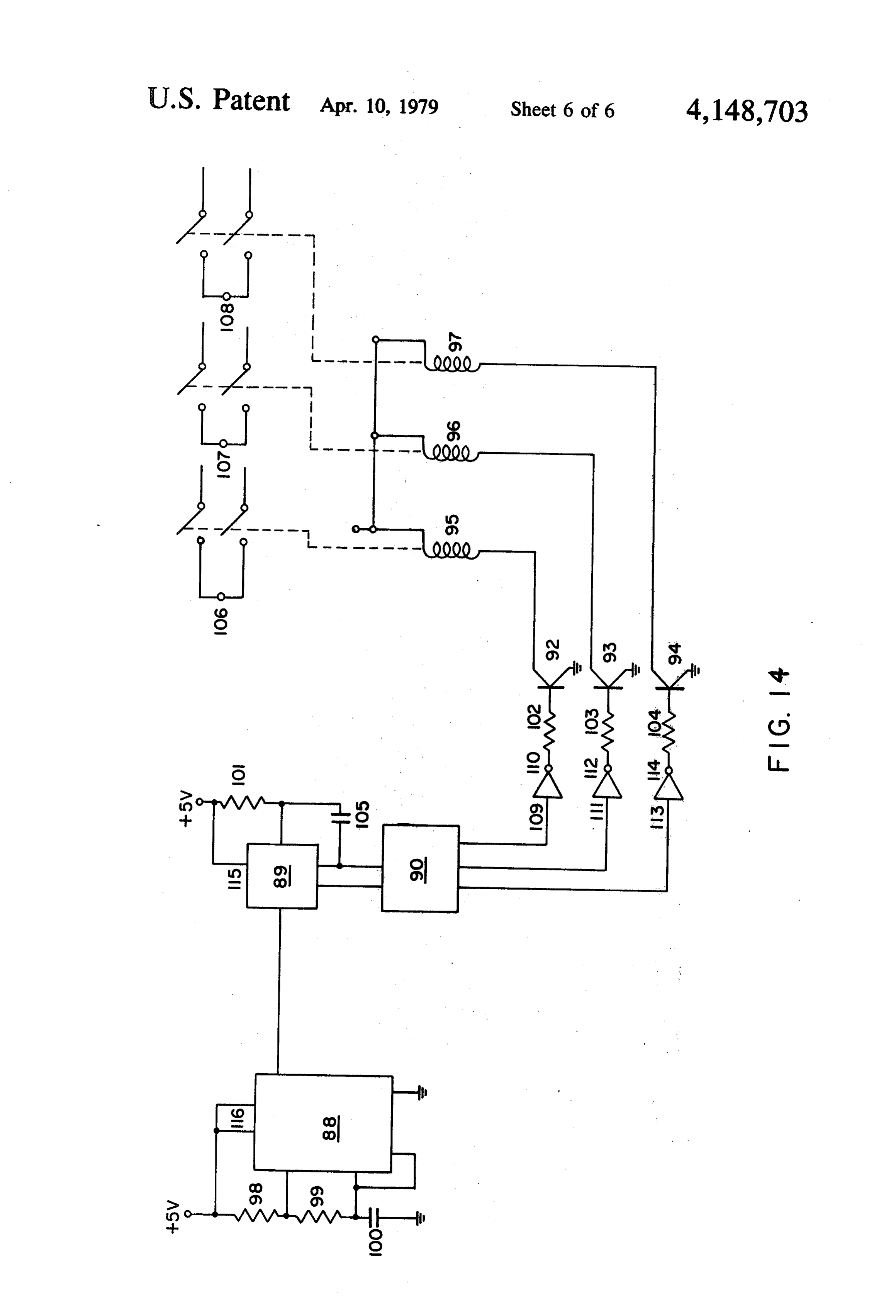
neously, but rather intermittently, during short periods 65 FIGS. 14 and 15 illustrate the electronic switching of time, switched automatically by controlled automatic network.
switches. However the gel itself is under a convertable FIG. 16 is a drawing depicting the connection system single electrical field continuously. The intensity of one of the main classes and the electrode nodule.
Page 9
FIG. 12 shows the scheme of the various parts of the tion of electrode systems, automatic switching, diver electrophoresis apparatus and the different flowing gent geometrically shaped electrode systems, and repet fractions. FIGS. 1, 2, 3 & 4 show the scheme of the itive & selective operations of the said systems. separating vectors. FIGS. 9, 10 & 11 shows different The 18 different classifications include the following: kinds of modularized electrodes. 1. The Microscopic (analytical) medium type which is a free supporting medium, contains one pair of paral
DESCRIPTION OF PRIOR ART lel electrodes in an equal field. (See reference #1). Enzymes and peptides are protein molecules that 2. The Boundary (analytical) medium type which catalyze and perform chemical reactions on animals, includes a free supporting medium (see reference #2) or plants, and microorganisms. The enzymes cause the 10 which includes a supporting medium where no molecu chemical reactions to occur thousands and even mil lar sieving is performed (see reference #3) contain one lions of times faster than if the enzymes were not pres pair3. ofThe parallel electrodes in an equal field. Zone Electrophoresis (analytical) medium ent. In the human body alone there are more than a thousand different types of enzymes. Industrial enzymes type which includes a supporting medium of no molecu are derived from plant or animal tissue or from the cells 15 lar sieving (see reference #4) or which includes a sup of microorganisms. To obtain these endoenzymes the portive medium of molecular sieving (see reference #5) cells of the enzyme source are removed from its associ contain only one pair of parallel electrodes in an equal ated liquid which contain the secreted enzyme. When field. 4. The Zone Electrophoresis Preparative (two-stage) necessary, preservatives are added to these extracts, which are sybsequently clarified. Enzyme syrups or 20 medium type, which includes a free supporting medium powdered preparations are made from these solutions (see references #6 & #7), or which includes a support which are concentrated but not highly purified. The ing medium of no molecular sieving (see reference #8) production of high purity enzymes require alternative or which includes a supportive medium of molecular steps, successive and/or independent, which start with sieving (see reference #9) contain only one pair of par the raw material or protein mixture. These steps in 25 allel5. electrodes in an equal field. The Zone Electrophoresis Preparative (single clude: fractional precipitation; differential adsorption and elution; chromotography; electrophoresis; dialysis; stage (a) flow elution) medium type, which includes a crystalization; and freeze drying. supporting medium of no molecular sieving (see refer Electrophoresis is widely used as a separation tech ence #10) or which include a supporting medium of nique, particularly in protein chemistry. It has been 30 molecular sieving (see reference #13) contain only one valuable as a "gentle' analytical method for complex pair6. of parallel electrodes in an equal field. The Zone Electrophoresis Preparative (continu organic material enzymes, hormones, proteins, colla ous) medium type which includes a supporting medium gens, amino acids, nucleotides etc. that are changed and destroyed by heat or chemical action. Many kinds of (see reference #14 & #15) or which includes a support electrophoretic apparatuses have been developed in 35 ive medium of no molecular sieving (see references #16 order to achieve convenient, inexpensive, and relatively & #17) or which includes a supportive medium of mo rapid methods of purifying large quantities of proteins lecular sieving (see reference #18) contain only one pair or providing a high purification. However, there is no of parallel electrodes in an equal field. electrophoretic method at present that utilizes an appli All these 18 different classifications of medium types, cation of purifying enzymes and peptides which per 40 include approximately, more or less, 100 different form both of these results together and simultaneously known techniques and approaches, all of which do not to yield a higher purification and to provide purification make use of the innovative features of our invention on a large scale. Nevertheless, physicochemical and automatic which consist of modularization of electrode systems, structural studies of proteins demand that the protein be switching, divergent geometrically shaped extremely high in purity and require rather large quanti 45 electrodes, and the repetitive and selective operations of ties of the purified protein. the said systems.
Since 1808, when Reuss first discovered the potenti SUMMARY OF THE INVENTION alities of the method of electrophoresis by observing the transfer of water from an anode chamber to the cathode It is therefore among the principal objectives of this chamber as an electric current passed through an earth 50 by invention to improve on the method of electrophoresis enware diaphragm, and 1880, when Kohlrausch, Henry satisfying two conditions simultaneously, the high and others developed the electrokinetic theory, and purification of enzymes and peptides and the purifica 1930, when Tiselus developed the moving boundary tion of enzymes and peptides on a large scale, without method, the improvements in the electrophoretic pro the retic usual concomitant disadvantages of non-electropho purifying techniques, requiring increased proce cess has been vast and worthy indeed. At the present 55 time there are at least 18 different classifications of dural steps, increased time, increased labor, & increased electrophoretic methods based upon medium types, and costs. The improvement contemplates and includes approximately 100 more or less different techniques within its scope a continous preparative electrophoresis within these classifications, however, each one of these in which polyacrylamide gel serves a medium for con classifications have not altered or modified the standard 60 tinuous separation but without a flowing of the buffer application of one pair of parallel electrodes in an equal through the gel. The new method conceives a separa field. Each one of these classifications do not provide tion in a rectangular thin layer gel placed between two the simultaneous results of both high purification of separate independent field systems perpendicular to enzymes and peptides and purification of the same on a each other. The two electrical field systems do not large scale. A review of all the present classifications of 65 function simultaneously, but rather operate during short electrophoretic processes include the following me periods of time and are switched automatically by con dium types all of which do not contain the innovative trolled automatic switches. The gel itself is continu ously under a convertable single electrical field. The features of our invention which consist of modulariza
Page 10
intensity of both fields is adjustable by its geometric These are situated alongside the periphery of the shape and makes a gradient form alongside the width of chassis.
the field applied onto the gel layer. This is accom C. Accessories of the System which include those plished by the introduction of both electrodes in a diag systems that aid indirectly the separation process per formed by the chassis main body and the chassis sub onal position in such a way that the resistance of the 5 body.
medium is gradually decreased along the width of the 1(81) Feeding system-which contains a pump, tub field. The apparatus and temperature is regulated by achieving fractionation of heat sensitive materials. The ing,2. and an interconnecting reservoir to the gel. Output buffer system-which contains a pump, enzymatic preparation mixture is introduced into the gel continuously by a very slow constant flow through 10 reservoir of buffer.
a thin tubing into a hole crossing the thickness of the gel ant3.reservoir,
Cooling system-which contains a pump, refriger during the application of the electrical fields. The verti refrigerant. circulating wrapped coils of water or a cal field "separates' the proteins according to their mobility in the field, on account of the net electric tains 4. (85) Electronic switching network-which con charge, the molecular dimension, and the molecular 15 tive and positive and negative accelerating electrodes, posi construction, by applying on them a vertical vector (A). and negative negative separating electrodes, and positive The horizontal electrical field applies a horizontal vec separating electrodes. tor (B) and causes the proteins to move horizontally. time interval of &switching
In FIGS. 14 5 a. Timer-which determines the from one system to the next.
The proteins pass through the gel and out via a series of In FIGS. 14 & 15 b. Counter-which counts the tiny holes across the thickness of the gel, eluted by the 20 pulses from the timer to distinguish each count, thereby flowing buffer which runs during the operation. The defining the status, acceleration, positive separation and gradient factor enables the faster fractions to emerge negative separation.
sooner and closer to the application point than the In FIGS. 14 & 15 c. Decoder-which differentiates slower ones. An ambient temperature is maintained at 25 the states from the counter, decodes the states of the the needed degrees by the circulation coolant around a vertical plate, from a refrigerated bath, permitting pre counter, binary and and receives the counter's, output which is decodes it to individual outputs.
parative separation for heat labile substances sych as The specification includes the following dimensions, enzymes. The modularized interchangeable parts con time intervals, and ranges:
tain several diverse configuration including diagonal 30 Length of gel-range from 3.5 centimeters to 30 cen linear electrodes, exponential electrodes, arced shaped timeters.
electrodes, and other geometrically shaped electrodes. Width of gel-range from 2 centimeters to 20 centi These different geometric shapes apply different parti meters.
cle velocities, thereby enabling a finer separation, & a Current: 250 to 1000 volts. continuous electrophoresis, by means of higher voltage 35 Feeding rate-from 15 to 50 miligrams an hour of in a smaller area with less expenditure of power. These crude protein.
different geometric shapes allow a high purification of High purification-one bent Drawings consist of the enzymes and peptides simultaneously, as the continuous following: FIGS. 1, 2, 3 & 4 illustrate the principle of electrophoresis permits purification of enzymes and the separation of enzymes and peptides by a combina peptides on a large scale. 40 tion of two perpendicular lines. While for the ease of convenience the specification In FIG. 1: 1-represents the inlet hole; 2-the outlet will refer throughout the application to the following holes; 3-the line movements of enzyme or peptide Structures: fractions; 4-horizontal separating negative electrodes; A. Chassis Main Body (FIG. 13; 7) which includes a 5-horizontal separating positive electrodes; 6-verti rectangular structure containing gel that has input ports 45 cal accelerating negative electrodes; 7-vertical accel for crude preparation and output ports for the enzyme erating positive electrodes. FIG. 1 depicts the diagonal output, interconnection brackets for the connection of linear electrodes.
accelerating and separating electrodes, and electrode In FIG. 2:9-represents the inlet hole; 11-the outlet systems. On the left side, where the positive particles holes; 10-the line movements of enzyme or peptide gravitate, is located the positive separating electrode 50 fractions; 12-horizontal separating negative elec system which separates only positive electrodes, posi trodes; 13-horizontal separating positive electrodes; tive separating electrodes positive, and positive separat 14-vertical accelerating negative electrodes; 15-ver ing electrodes negative. On the right side, where the tical accelerating positive electrodes; 16-the gel. FIG. negative particles gravitate, is located the negative sep 2 depicts the ball electrodes.
arating electrode system which separates only negative 55 In FIG. 3:17-represents the inlet hole; 18-repre electrodes, negative separating electrodes negative, and sents the outlet holes; 19-the line movements of en negative separating electrodes positive. zyme or peptide fractions; 20-horizontal separating B. Chassis Sub Body which include the electrodes negative electrodes; 23-horizontal separating positive that are hooked up to the sides: electrodes; 21-vertical accelerating negative elec 1. (77) Cross accelerating electrodes, positive and 60 trodes; 22-vertical accelerating positive electrodes; negative ones. 24-the gel. FIG. 3 depicts the parabolic electrodes. 2. Separating electrodes which go along side the In FIG. 4:25-represents the inlet hole; 26-the out length of the chassis body, both for positive enzymes let holes; 27-the line movements of enzyme or peptide and negative enzymes. fractions; 30-horizontal separating negative elec (a) (78) Negative separating electrodes, both positive 65 trodes; 28-horizontal separating positive electrodes; and negative. 29A-vertical accelerating negative electrodes; 29B-. (b) (79) Positive separating electrodes, both negative vertical accelerating positive electrodes; 31-the gel. and positive. FIG. 4 depicts the parallel linear electrodes.
Page 11
FIGS. 5, 6, 7 & 8 illustrate the three chambers com separating power supply; 108-negative separating bined to form an electrophoresis cell. power supply.
In FIG. 5:32-represents chamber #1; 33-inlet FIG. 16 is a drawing depicting the connection system mouthpiece of circulating water coolant; 34-outlet of the main chassis and the electrode module. 119 mouthpiece of circulating water coolant; 35-outlet 5 main chassis; 120-electrode module. mouthpiece and central channel hole which provides Describing now the application of the "Adjustable passage for the crude extract preparation waste. Specialized, Geometrically Located Electrode Sys 39-the comb-like holes which receives the elution ten.
buffer. 1. Three chambers, forming the chassis main body, FIG. 6 represents chamber #2; 40-the comb-like 10 will be assembled individually, to be subsequently at holes which receive the elution buffer; 41-outlet cen tached in bayonet fahion, whereby the plugs of the tral channel hole which provides passage for the crude electrode system modules are bayonetted into the cham extract preparation waste; 42-inlet mouthpiece for bers, which are arranged like a sandwich, wherein electrode buffer circulation; 43-outlet mouthpiece for 15 chamber #3 and chamber #1 are the outer layers and electrode buffer circulation. chamber #2 is the inner layer, wherein chamber #3 the FIG. 7 represents chamber #3; 44-inlet mouth top layer, contains circulating water coolant sheathed in piece for crude extract penetration; 4.5-inlet chamber plastic, chamber #2 contains a batch of polyacrylamide and mouthpiece for passage of eluting buffer into elec gel, electrodes and buffer, and chamber #1, the bottom trophoretic unit; 46-inlet holes for electrodes; 47-in layer contains circulating water coolant sheathed in let mouthpiece of circulating water coolant; 48-outlet 20 plastic.
mouthpiece of circulating water coolant. 2. A batch of gel is prepared for the entire system FIG. 8 represents the 3 chambers combined; 49 consisting of the chassis main body and the modularized chamber #3; 50-chamber #2; 51-chamber #1; 52 electrodes. The gel is placed in chamber #2, filling it chamber joiner screws. 25 out, between the casing of the chassis main body and cut FIGS. 9, 10 & 11 illustrates the electrode modules. away with a cutout to a predetermined form corre FIG. 9:51-platinum wire; 54-plastic sheath; 55 sponding to the geometric shape of the specialized geo plug. FIG. 9 depicts the diagonal linear electrode mod metric electrode module, selected from a repertoire of ule. different specialized geometric shaped electrode mod FIG.10: 56-platinum wire; 57-plastic sheath; 58 30 ules, such as a diagonal linear shaped electrode module, plug. FIG. 10 depicts the diagonal linear electrode mod a point and ball shaped electrode module, a parabolic ule. shaped electrode module, an arced shaped electrode FIG. 10 depicts the parabolic electrode module. module and other geometrically chaped electrode mod FIG. 11:59-ball coated with platinum; 60-plug. ules, to purify specifically enzyme or peptide "X'. The FIG. 11 depicts the ball electrode module. 35 gel shape that has been cut away is limited and pro FIG. 12 illustrates the fluids flow system. 61-inlet scribed by the geometric shape of the electrode module. hole chamber of the eluting buffer; 62-anode inlet; The superfluous gel, that portion of the gel which ex 63-cathode inlet, combined electrophoretic chambers; tends beyond the boundaries of the geometric shape of 65-chamber #3; 66-chamber #2; 67-chamber #1; the electrode module, is detached and removed from 68-inlet of the crude extract preparation into the cell; the chassis.
69-fraction hoses, passage of fractions following sepa 3. Appropriate size channel hole is cut out of the ration; 70-fraction collector tubes or bottles; 71-elut center of the gel of chamber #2 corresponding to the ing buffer reservoir; 72-crude extract preparation res size and location of the prearranged hole in chamber #1 ervoir 73-electrode buffer reservoir; 74-cooling sys and chamber #3. Through the central channel hole in tem unit; 75-pump, for driving liquid; 76-cooling 45 chamber #3, down through the central channel hole in water sleeve. chamber #2, and down through the central channel FIG. 13: Block drawing of modularized chassis and hole in chamber #1, each channel hole directly below subchassis: 77-main chassis body; 78A-cross acceler the channel hole above it, flows the crude extract prepa ating electrode module positive; 78B-cross accelerat ration of enxymes, peptides and other biomolecules. ing electrode module negative; 79A-negative separat 50 4. Appropriate size comb-like holes, similar to holes ing electrode module, positive; 79B-negative separat formed by the teeth of a comb on a batch of gel, will be ing electrode module, negative; 80-positive separating cut out of the gel in chamber #2, which said holes will electrode module, positive; 80-positive separating form two straight parallel lines, one line of holes situ electrode module, negative; 81-input feed system, ated higher than the other line of holes, by about 2 crude extract preparation; 82A-to output buffer sys 55 centimeters, each line containing from 10 to 20 evenly tem; 82B-to output buffer system; 83A-comb-like spaced comb-like holes, which correspond in size and holes, output; 83B-comb-like holes output;-cooling location to the comb-like holes found in chamber #1. system;-electronic switching network;-power sup These comb-like holes found in chamber #2 and cham ply;and-electrode buffer pumping system network are ber #1 will subsequently receive elution buffer, which part of the system but not shown in this Figure. 60 said buffer will flow through the hollow in chamber #3. FIGS. 14 & 15 illustrate the electronic switching 5. The separating electrodes and the accelerating network; 88-represents a NE555 timer; 89-74163 electrodes, platinum wires coiled or elongated along binary counter; 90-74154 decoder; 91-7405 hex in side plastic, are connected to electrode switching cir verter; 92,93, 94-2N2222A NPN transistors; 95, 96, cuit which in turn will be connected to the power sup 97-high voltage relays; 98, 99, 100 are adjusted to 65 ply. The automatic switching network will be set to obtain a frequency of 1 beat per second; 101-1K resis operate, theoretically, 24 hours a day, thereby provid tor; 102, 103, 104-1K resistor; 105-0.001 ufd capaci ing a continuous separation. The chamber #2 is filled up tor; 106-accelerating power supply; 107-positive over its entire area with electrode buffer.
Page 12
6. The mounting screws are tightened both to hold 1. A batch of gel is prepared for the entire system the electrode modules in place and to join all the cham consisting of chassis main body and the modularized bers together to form the complete chassis main body. electrdoes. The gel is placed between the casing of the 7. The electrode buffer circulation system is con chassis main body and the output portholes are formed. nected in the appropriate holes in chamber #3 so that The gel is also placed between the casing of the modu the electrode buffer will circulate from a hole in cham larized electrodes. The shape of each electrode is cut to ber #3, on the extreme left side of the chamber, down to a predetermined form, depending upon the electrode of chamber #2, through the area of chamber #2, and up the particular module.
through a hole in chamber #3, at the extreme right side 2. The platinum electrodes are placed into the cutout of chamber #3. The electrode buffer system circulates O and attached to the electrical connection. After this is by means of a pump and hoses, the pump pumping the done the system is ready to be used.
circulating buffer from the starting point the reservoir, via hoses, through chamber #2 and recirculating the for3.aThe system is now ready to be assembled to be used buffer via hoses, to the reservoir, located in a special the electrodespurpose specific which predetermines the type of to be used.
unit.
8. The cooling system of circulating water, circulates pump, 4. The chassis main body, the input pump, the output via hoses through chamber #3 and passes on downward and the output portholes are attached.
all the way via hoses leading outward, which said hoses front and back accelerating electrodes are attached to the connected to the outlets of the holes found on the bot of the chassis main body, and the elec tom of chamber #1. trode buffer system is attached to them. 9. The crude extract preparation of enzymes, pep 6. The mounting screws are tightened both to hold tides, and other biomolecules, is fed through the central thethe electrodes in place and to obtain a bettermingling of electrode gel with that of the chassis main body.
channel hole inlet, in chamber #3, by means of a pump, via a hose which passes down from the mouthpiece inlet are7. then The separating electrodes, of the chassis sub body, in chamber #3 down through the central channel in 25 data) and selected (depending on the predetermined mounted alongside the chassis main body chamber #3, down through the central channel in chamber #2, and down through the central channel in similar in manner as the accelerating electrodes. chamber #1, out through the mouthpiece outlet, which 8. The power supply is then connected to the elec said mouthpiece is attached to a hose which leads the trode switching circuit which is then connected to the residue of the crude extract preparation to a unit col 30 electrodes and the turn on switch. lecting waste. The end product, the purified enzyme or Describing now the action of the invention: See FIG. peptide, will be collected by fraction collecting tubes, 13:
which said tubes are connected to the mouthpieces of Article 81, the input feed system, which is a pumping the small hoses extending down from the bottom of mechanism, pumps the initial mixture into the separat chamber #1. 35 ing system, Article 77, which is the chassis main body 10. The circulating electrode buffer system will be system, contains the gel, the input porthole and the connected, the cooling system of circulating water will output portholes 83A and 83B. The mixture is then be connected, the crude extract preparation of enzymes accelerated via positive electrode 78A, and negative and peptides and other biomolecules will be fed through electrode 78B. During the cross acceleration the parti the connected hoses, through the central channel inlet. cles are separated to the sides toward the portholes by The elution buffer will be pumped. The circulating 79A and 79B, for positive particles which are the posi water coolant, however, will be pumped hour prior to tive separating electrodes or negative particles by 80A the purification process. The electrode switching cir and 80B which are the negative separating electrodes. cuit will be set in motion. All the electrodes are controlled by an electronic 11. The system is now ready to be used for the contin 45 switching network so that no two electrode systems are uous, one step operation, purification process of enzyme operating simultaneously. Eventually the particles or peptide 'X'. gravitate and collect at the output portholes 83A and 12. Every 4 to 5 hours the system's operation will be 83B, its path being a function of the electrical field, and supervised to monitor the temperature level. are forced out via the output buffer pumping system 13. At the close of the system's operation the special 50 82A and 82B. The temperature of the system is main ized geometric shaped electrode system module, most tained by a cooling system network, consisting of a suitable for the purification of enzyme or peptide "X" pump and coolant. The power supplies, provide power will be disconnected and removed from the chassis to the electrodes as needed.
main body, and in its place another specialized different Describing now the electronic switching method. geometric shaped electrode system module most suit 55 The oscilator beats at a frequency of approximately one able for the purification of enzyme or peptide "Y" will beat per second and feeds into the counter. The first be inserted in the chassis main body. The whole proce count is decoded by the decoder which turns on the dure will start anew from 1 through 13. accelerating electrode switches via the driver. The next Describing now the adjustability of the "Adjustable, beat of the oscilator advances the counter whose output Specialized, Geometrically Located Electrode Sys is decoded and turns on the positive separating elec tem'. trodes, via driver and switches. The next beat resets the The "Adjustable, Specialized, Geometrically Lo counter and the entire cycles starts all over again. cated Electrode System' may be adjusted and adapted to include the modularization of a complete chassis sub REFERENCES body, and a complete chassis main body, not just the 65 1. Ellis, G. (1912) Z. Phys. Chem. 78 321 electrode system module alone. Describing now the 2. Tiselius, A. (1937), Trans. Faraday Soc. 33524 preparation of the adjusted and adapted system and the 3. Lodge O. (1886), Report of British Assoc. for the said system's assembly. Advancement of Science Birmingham P.389
Page 13
4. Hjerter S. Jersedt and A. Tiselius (1969), Annal Bio applying a vertical vector, by means of the vertical chemistry 27 108 electrical field systems, to separate the enzymes 5. Smith I. (1968), "Chromotography and Electropho and peptides in accordance with their mobility; retic Techniques' Vol.2, "Zone Electrophoresis' and,
Whey. New York 5 applying a horizontal vector, by means of the hori 6. Zweig G. and Whitaker J. P., "Paper Chromotogra zontal electrical field systems, to cause the enzymes phy and Electrophoresis' Vol. 1, "Electrophoresis in and peptides to move horizontally. Stabilizing Media” Acad. Press N.Y., 1967 2. An improved method as recited in claim 1 compris 7. Durrum E. I. (1950), Aemr. Chem. Soc. 722943 ing the further step of alternately selecting the various 8. Smithies, O. (1955) Nature 175 309 O electrode systems by means of automatic switching, 9. Raymond S. and Weintraub L. (1959), Science 130 which said automatic switching turns on and off said 711 electrode systems independently of one another for a 10. Svenson H. (1948), Advan. Protein Chem. 4251 given period of time and which said automatic switch 11. Svenson H. and Walmet E. (1955), Sci. Tools 2 11 ing maintains a clearly defined electrical field distribu 12. Kunkel H. G. and Slater E. (1952), Proc. Soc. Exp. 15 tion3. and gradient along the width of the gel. An improvement in the method of electrophoretic
13. Rayomnd S. (1964), Science 146 406 purification of enzymes and peptides on a polyacryl 14. Porath J. Lindner E. B. and Jerstedt S. (1958), 182 amide gel, wherein the improvement includes the selec tive application of divergent geometrically shaped elec
15. Murray K. (1962), Anal. Biochem. 3 415 20 trode systems, which said divergent geometrically 16. Jovin T., Chrambach A., and Naughton M. A. shaped electrodes enable a high purification continu (1964), Anal. Biochem. 21 190 ously on a large scale, which said improved method 17. Schenkin I., Levy M., and Weis P. (1968), Anal. having steps comprising:
Biochem. 25387 Applying different particle velocities by means of 18. Boyde T. R. C. (1971), Occasional Paper #7 from 25 divergent geometrically shaped electrode systems; the Dept. of Biochem. Makerere Univ. Kampala and, 19. Philipot J. Sr. L. (1940), Trans. Faraday Soc. 36 enabling a finer separation and a continuous separa 20. Barrollier J., Watzke E. and Cibian I. (1958), Z. tion of said enzymes and peptides by means of an Naturforsh 13 b. 754 increased voltage in a decreased area. 21. Grossmann W. and Hannig K. (1949), German Pat. 30 ing4.the An improved method as recited in claim 3 compris further step of inserting or removing divergent #805,344 geometrically shaped electrode systems by means of 22. Boyde T. R. C. and Remtulla M. A. (1973) Anal.
Biochem. 55 492 diverse modularized interchangeable units of divergent What is claimed: geometrically shaped electrodes which said inter 1. An improvement in the method of electrophoretic 35 changeable units having interconnection bracket means purification of enzymes and peptides on a polyacryl to hook onto the side of the rectangular gel structure. amide gel, wherein the improvement includes the adap 5. The purification method using divergent geometri tation of geometrically located electrode systems situ cally shaped electrode systems, as recited in claim 3, ated both in a vertical electrical field and in a horizontal which said electrode systems comprising concave and electrical field, which said improvement enables a high convex electrode systems.
6. The purification method using divergent geometri purification simultaneously as it allows purification on a large scale, which said improved method having steps cally shaped electrode systems as recited in claim 3, comprising: which said electrode systems comprising point and ball Situating divergent geometrically located and diver electrode systems.
gent geometrically shaped electrode systems in 45 7. The purification method using divergent geometri two separate electrical fields, which said electrical cally shaped electrode systems as recited in claim 3, fields comprise a vertical electrical field and a hori which said electrode systems comprising U shaped, zontal electrical field; inverted U shaped, V shaped and inverted V shaped operating said electrical fields intermittently during electrode systems. k k k k selective repetitive periods of time; 50
Provenance
- Collection
- Cited prior art
- Original PDF
- patentimages.storage.googleapis.com →
- Filed
- 1976-02-11
- Pages
- 13
- Method
- pdftotext (the PDF's own text layer) + pdftoppm 300dpi page scans
- Source
- Google Patents bibliographic record
- Granted
- 1979-04-10
- Inventors
- Moshe Trop; Joseph Herbst
- Transcribed from
- patentimages.storage.googleapis.com →