patent · US4530744
Method and apparatus for the producing of liquid hydrogen
23 July 1985
Page 1 — bibliographic record
United States Patent (19)
Smith
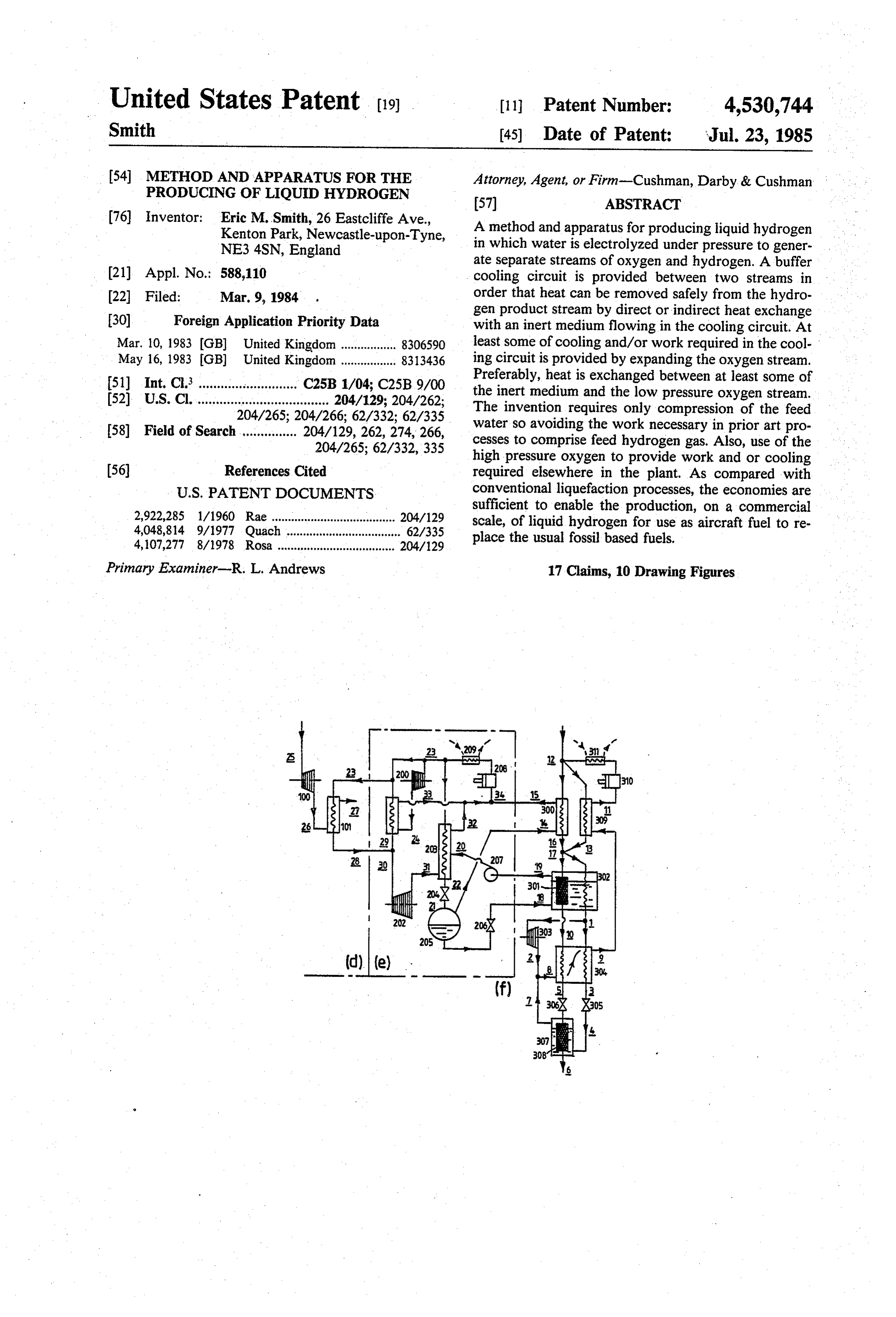
54 METHOD AND APPARATUS FOR THE Attorney, Agent, or Firm-Cushman, Darby & Cushman PRODUCING OF LIQUID HYDROGEN 57 ABSTRACT 76 Inventor: Eric M. Smith, 26 Eastcliffe Ave., A method and apparatus for producing liquid hydrogen Kenton Park, Newcastle-upon-Tyne, in which water is electrolyzed under pressure to gener NE3 4SN, England ate separate streams of oxygen and hydrogen. A buffer (21) Appl. No.: 588,110 cooling circuit is provided between two streams in 22 Filed: Mar. 9, 1984 order that heat can be removed safely from the hydro 30) Foreign Application Priority Data gen product stream by direct or indirect heat exchange with an inert medium flowing in the cooling circuit. At
Mar. 10, 1983 (GB) United Kingdom................. 8306590 least some of cooling and/or work required in the cool May 16, 1983 GB United Kingdom ................. 8313436 ing circuit is provided by expanding the oxygen stream. 51) Int. Cl............................ C25B 1/04; C25B 9/00 Preferably, heat is exchanged between at least some of 52 U.S. Cl. .................................... 204/129; 204/262; the inert medium and the low pressure oxygen stream. 204/265; 204/266; 62/332; 62/335 The invention requires only compression of the feed 58) Field of Search............... 204/129, 262,274, 266, water so avoiding the work necessary in prior art pro 204/265; 62/332,335 cesses to comprise feed hydrogen gas. Also, use of the high pressure oxygen to provide work and or cooling (56) References Cited required elsewhere in the plant. As compared with
2,922,285 l/1960 Rae ...................................... 204/129 sufficient to enable the production, on a commercial 4,048,814 9/1977 Quach ................................... 62/335 scale, of liquid hydrogen for use as aircraft fuel to re 4,107,277 8/1978 Rosa .................................... 204/129 place the usual fossil based fuels. Primary Examiner-R. L. Andrews 17 Claims, 10 Drawing Figures
Page 2
Drawing sheet — no readable text.
Page 3
Drawing sheet — no readable text.
Page 4
Drawing sheet — no readable text.
Page 5
Drawing sheet — no readable text.
Page 6
Drawing sheet — no readable text.
Page 7
Drawing sheet — no readable text.
Page 8
Drawing sheet — no readable text.
Page 9
Drawing sheet — no readable text.
Page 10
Drawing sheet — no readable text.
Page 11
Drawing sheet — no readable text.
Page 12
by heat exchange optionally via an intermediate heat
METHOD AND APPARATUS FOR THE exchange stage, with an inert medium flowing in a sepa PRODUCING OF LIQUID HYDROGEN rate cooling circuit, and comprising apparatus for the electrolysis of water under pressure to produce the
This invention relates to a method of and apparatus 5 hydrogen product stream and an oxygen stream both for the production of liquid hydrogen. under pressure, and expansion means connected to the Arising from the recognition that stocks of fossil fuels oxygen stream and supplying low pressure oxygen to a are rapidly depleting much research has, in recent heat exchanger in the cooling circuit for the inert me years, been directed to the search for alternative sources dium.
of fuels and raw material. Hydrogen is now seen as an 10 In a preferred embodiment, the apparatus comprises a important secondary or convenience fuel, as a means of hydrogen liquefaction module receiving a stream of distributing power generated by nuclear or hydropower hydrogen under pressure from the electrolysis means, souces in small packages for transport and power gener an oxygen module receiving a stream of oxygen under ation, as a desirable feedstock in the conversion of solid pressure from the electrolysis means and including the fossil fuels into synthetic gaseous and liquid fuels, and as 15 said expansion means, and a buffer cooling circuit con a major feedstock for the ammonia fertilizer industry. nected between the hydrogen liquefaction module and The use of liquid hydrogen as a fuel particularly for the oxygen module and comprising a closed circuit jet aircraft, has a number of environmental and techno refrigeration system for an inert medium including a logical advantages over conventional fuels and liquefac heat exchanger in which the inert cooling medium is tion plants capable of operating on a commercial scale 20 cooled against low pressure oxygen received from the have been developed. At present levels, however, a cost expansion means, the hydrogen liquefaction module comparison with existing fuels is unfavourable particu including a first heat exchanger in which the hydrogen larly when the source of hydrogen is electrolysis, which product stream is cooled against the inert medium flow is accepted as the most likely source for providing the ing in the cooling circuit.
vast volumes required were hydrogen to become uni 25 Heat is also removed from the hydrogen product versally accepted as the fuel to replace conventional stream attemperatures below the temperature at which fossil based fuel. heat exchange occurs with the inert medium cooling It is recognised that a key problem in the develop circuit, to produce liquified hydrogen. This may be by ment of hydrogen technology is the energy cost of heat exchange first with gaseous hydrogen and later liquefaction of hydrogen. In a paper entitled "A study 30 with liquified hydrogen in a hydrogen refrigeration of the efficiency of hydrogen liquefaction', C. R. Baker system, preferably an open cycle refrigeration system. and R. L. Shaner (Int. J. Hydrogen Energy 1978, vol. 3 Alternatively, such low temperature heat exchange pp. 321-334) a typical liquefaction plant is described may be with hydrogen or helium, preferably gaseous having three distinct process streams, a liquid hydrogen helium, in a closed cycle refrigeration system or by product stream, a hydrogen recycle stream and a cold 35 magnetic cooling as described in "Can Magnetic refrig nitrogen stream of which the nitrogen stream supplied erators liquefy hydrogen at high Efficiency": J. A. Bar partly as liquid and partly as cold gas, and the hydrogen clay: ASME paper 81-HT-82, 20th Joint AS recycle stream provides the refrigeration needed for ME/AIChE National Heat Transfer Conference, Au liquefaction of the product stream. This paper points to gust 1981.
the hydrogen compressor efficiency and nitrogen re Other than hydrogen, helium is the only fluid suitable frigerator efficiency as the two areas affording the for refrigerating liquified hydrogen at the lowest tem greatest opportunity for improving the process effi perature (during conversion from ortho- to para-hydro ciency although it was then thought that improvements gen). Hence the operating pressure at the lowest tem will be both marginal and difficult to achieve. perature level (approx 20' K.) need not be sub-atmos One object of the present invention is to gain im 45 pheric, which is advantageous having regard to the provement in the efficiency of liquefaction of hydrogen amount of recycle compression work required in a by other means. closed cycle helium refrigeration system. : What I propose in accordance with the present inven In this specification, the terms "high pressure' and tion is to perform electrolysis of water under pressure as "low pressure' used in relation to the gases, nitrogen is known per se, so providing a hydrogen product 50 and hydrogen are intended to means any pressure above stream and an oxygen stream under pressure and to use and below the critical pressure for each gas respec the oxygen pressure stream by-product of electrolysis tively. Typical high pressure may be between the criti to provide work and/or cooling for the liquefaction of cal pressure for hydrogen (say 13 bar) to 250 bar and up the hydrogen product stream. to 100 bar for nitrogen. Typical high pressure for oxy According to one aspect of the present invention, I 55 gen corresponds approximately to the electrolysis pres propose a method of producing liquid hydrogen com sure for hydrogen, say 45 bar. "Low pressure' implies prising electrolysing water under pressure to generate pressure between bottom end of "high pressure' range separate streams of oxygen and hydrogen gas under and zero.
pressure, removing heat from the hydrogen stream "Open cycle'hydrogen refrigeration system refers to during liquefaction thereof by heat exchange optionally an arrangement in which the hydrogen liquefaction via an intermediate heat exchange stage, with an inert stream may mix with the recycle hydrogen refrigera medium flowing in a separate cooling circuit, and ex tion stream at one or more points. A "closed cycle' panding the oxygen stream to produce work and/or refrigeration system is not so connected to the hydro cooling for the inert medium cooling circuit. gen liquefaction system. According to another aspect of the present invention, 65 By performing electrolysis of water under pressure it I propose apparatus for the production of liquid hydro is required only to compress to feed water so avoiding gen and the like in which, during liquefaction of the the work necessary in the prior art processes and appa hydrogen product stream, heat is removed therefrom ratus to compress a supply of gaseous hydrogen prior to
Page 13
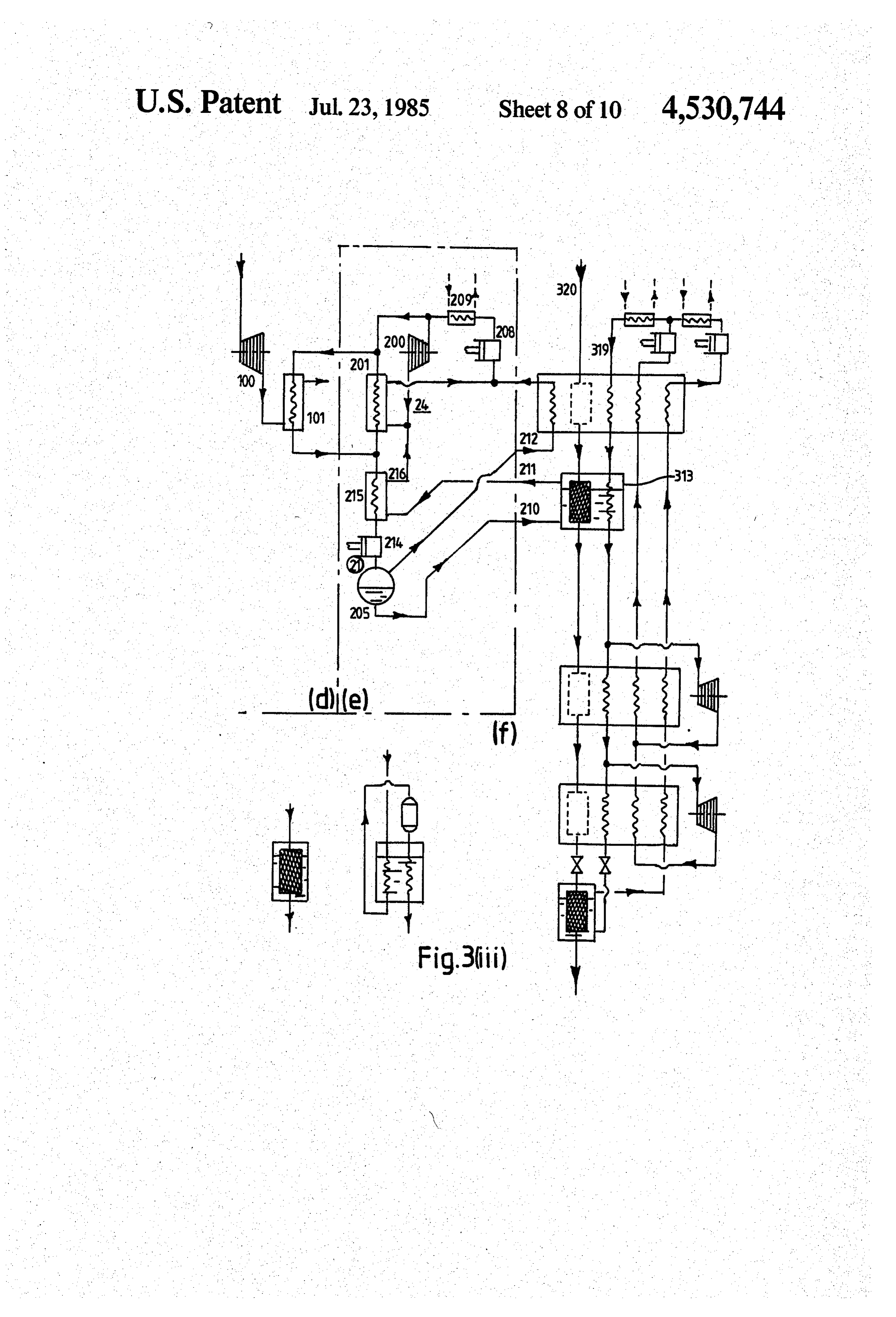
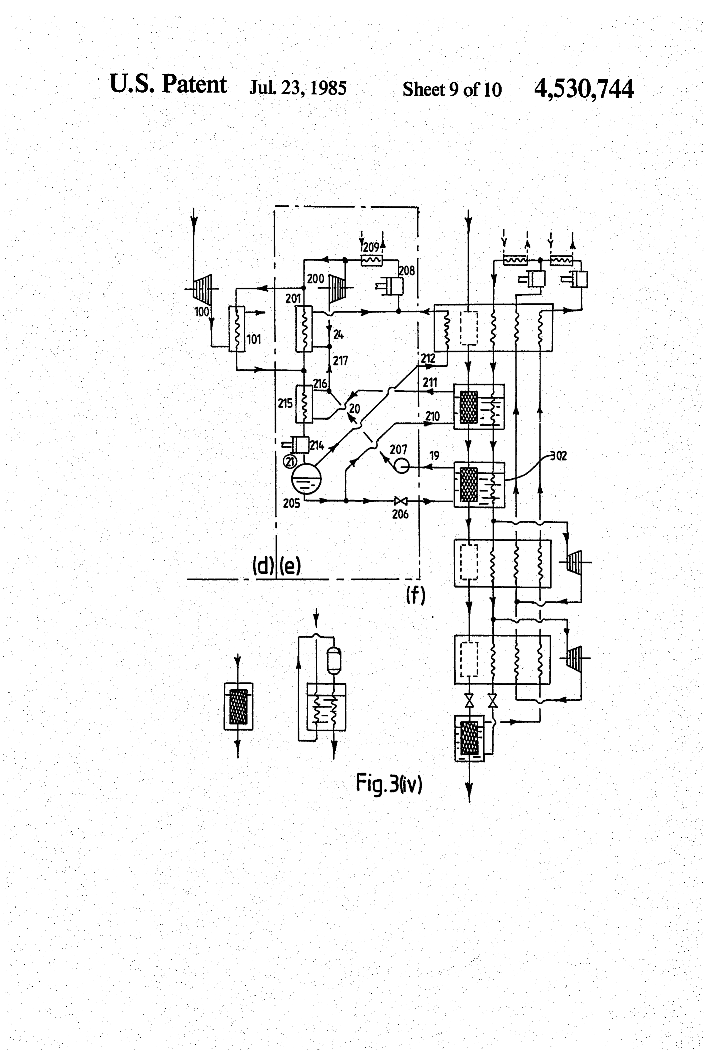
liquefaction. Further economies arise by using expan FIG. 2(iv) is a diagram similar to FIG. 2(i) but with a sion of near ambient temperature oxygen gas from high different nitrogen liquefaction module e, and a different pressure to atmospheric pressure in, for example, expan hydrogen liquefaction module f;
sion engines, which may have inert gas bearings, and/or FIG. 3(i) is a diagram showing details of another expansion throttles to produce work and/or cooling arrangement of the modules, d, e and f in the embodi required by the rest of the plant. ment of FIG. 1;
To optimise the conditions within the inert medium FIG. 3(ii) is a diagram similar to FIG. 3(i) but with a cooling circuit, it is possible to adjust the temperature different hydrogen liquefaction module f; level at which heat exchange with the low pressure FIG.3(iii) is a diagram similar to FIG. 3(i) but with a oxygen stream takes place. For example, auxiliary re 10 different nitrogen liquefaction module e, and a different frigeration may be introduced in the oxygen stream hydrogen liquefaction module f;
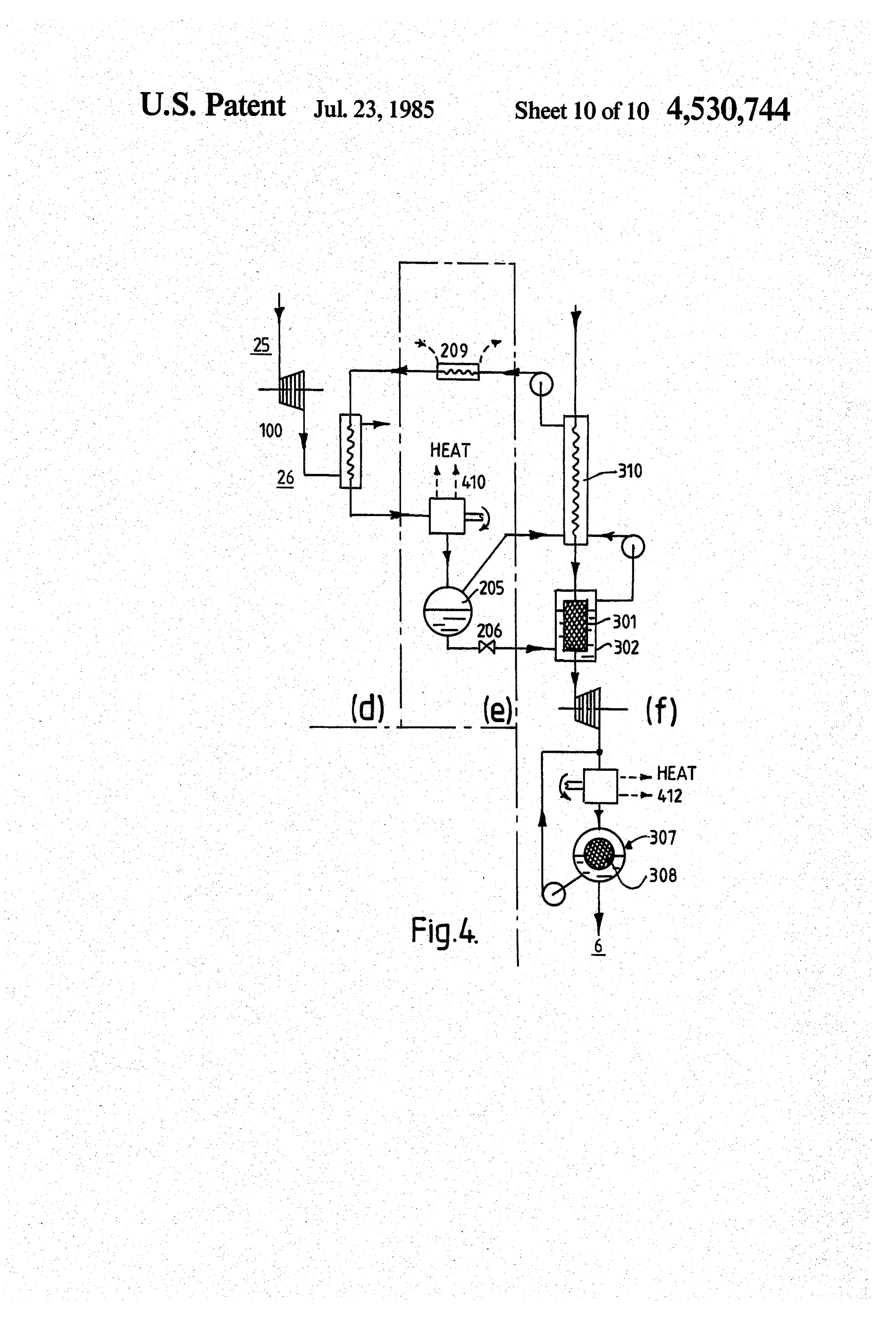
upstream of the oxygen expansion engine or equally in FIG.3(iv) is a diagram similar to FIG.3(i) but with a the inert medium cooling circuit. different nitrogen liquefaction module e and a different The inert medium cooling circuit, also acts as a buffer hydrogen liquefaction module f; and between the oxygen and hydrogen streams so enabling 15 FIG. 4 illustrates the use of a reversed Stirling-cycle heat to be transported from one stream to the other liquefaction machine in both the nitrogen module e and without the risk of explosion due to leakage of hydro the hydrogen module f.
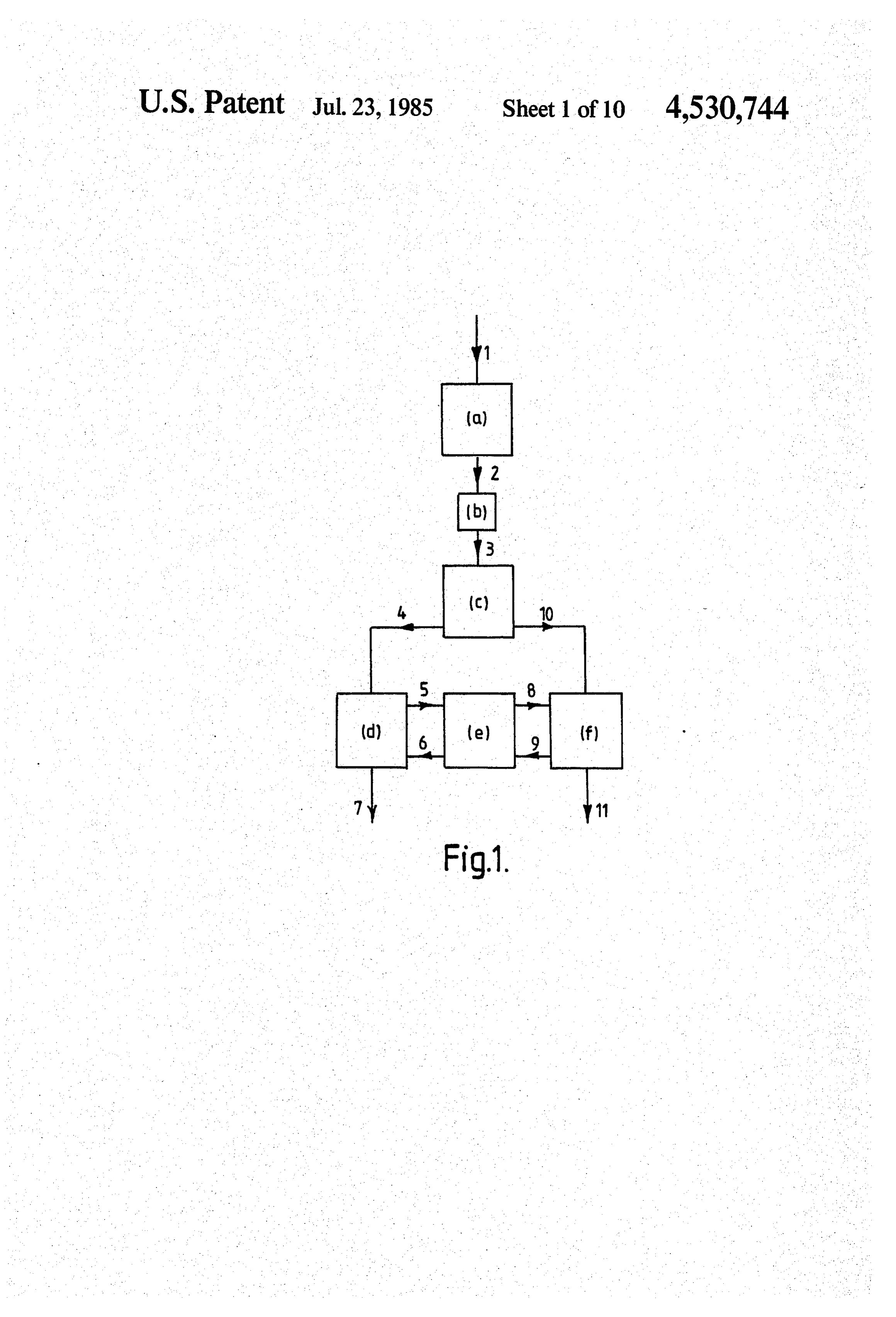
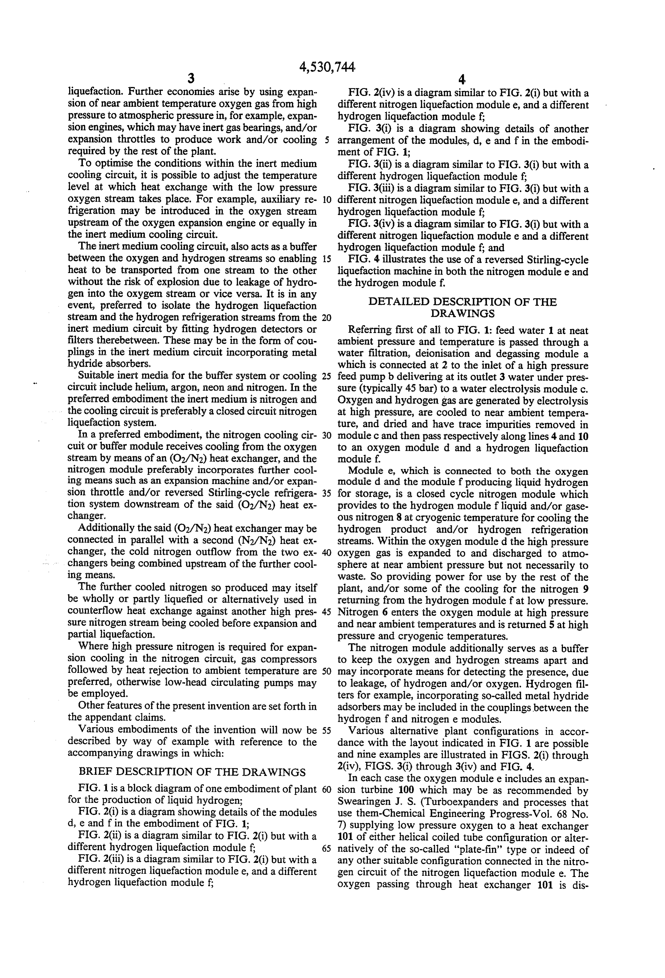
gen into the oxygem stream or vice versa. It is in any DETAILED DESCRIPTION OF THE event, preferred to isolate the hydrogen liquefaction DRAWINGS stream and the hydrogen refrigeration streams from the 20 inert medium circuit by fitting hydrogen detectors or Referring first of all to FIG. 1: feed water 1 at neat filters therebetween. These may be in the form of cou ambient pressure and temperature is passed through a plings in the inert medium circuit incorporating metal water filtration, deionisation and degassing module a hydride absorbers. which is connected at 2 to the inlet of a high pressure Suitable inert media for the buffer system or cooling 25 feed pump b delivering at its outlet 3 water under pres circuit include helium, argon, neon and nitrogen. In the sure (typically 45 bar) to a water electrolysis module c. preferred embodiment the inert medium is nitrogen and Oxygen and hydrogen gas are generated by electrolysis the cooling circuit is preferably a closed circuit nitrogen at high pressure, are cooled to near ambient tempera liquefaction system. ture, and dried and have trace impurities removed in In a preferred embodiment, the nitrogen cooling cir 30 module c and then pass respectively along lines 4 and 10 cuit or buffer module receives cooling from the oxygen to an oxygen module d and a hydrogen liquefaction stream by means of an (O2/N2) heat exchanger, and the module f.
nitrogen module preferably incorporates further cool Module e, which is connected to both the oxygen ing means such as an expansion machine and/or expan moduled and the module f producing liquid hydrogen sion throttle and/or reversed Stirling-cycle refrigera 35 for storage, is a closed cycle nitrogen module which tion system downstream of the said (O2/N2) heat ex provides to the hydrogen module fliquid and/or gase changer. ous nitrogen 8 at cryogenic temperature for cooling the Additionally the said (O2/N2) heat exchanger may be hydrogen product and/or hydrogen refrigeration connected in parallel with a second (N2/N2) heat ex streams. Within the oxygen moduled the high pressure changer, the cold nitrogen outflow from the two ex oxygen gas is expanded to and discharged to atmo changers being combined upstream of the further cool sphere at near ambient pressure but not necessarily to ing means. waste. So providing power for use by the rest of the The further cooled nitrogen so produced may itself plant, and/or some of the cooling for the nitrogen 9 be wholly or partly liquefied or alternatively used in returning from the hydrogen module fat low pressure. counterflow heat exchange against another high pres 45 Nitrogen 6 enters the oxygen module at high pressure sure nitrogen stream being cooled before expansion and and near ambient temperatures and is returned 5 at high partial liquefaction. pressure and cryogenic temperatures. Where high pressure nitrogen is required for expan The nitrogen module additionally serves as a buffer sion cooling in the nitrogen circuit, gas compressors to keep the oxygen and hydrogen streams apart and followed by heat rejection to ambient temperature are 50 may incorporate means for detecting the presence, due preferred, otherwise low-head circulating pumps may to leakage, of hydrogen and/or oxygen. Hydrogen fil be employed. ters for example, incorporating so-called metal hydride Other features of the present invention are set forth in adsorbers may be included in the couplings between the the appendant claims. hydrogen f and nitrogen e modules. Various embodiments of the invention will now be 55 Various alternative plant configurations in accor described by way of example with reference to the dance with the layout indicated in FIG. 1 are possible accompanying drawings in which: and nine examples are illustrated in FIGS. 2(i) through BRIEF DESCRIPTION OF THE DRAWINGS 20iv), FIGS. 3(i) through 3(iv) and FIG. 4. In each case the oxygen module e includes an expan
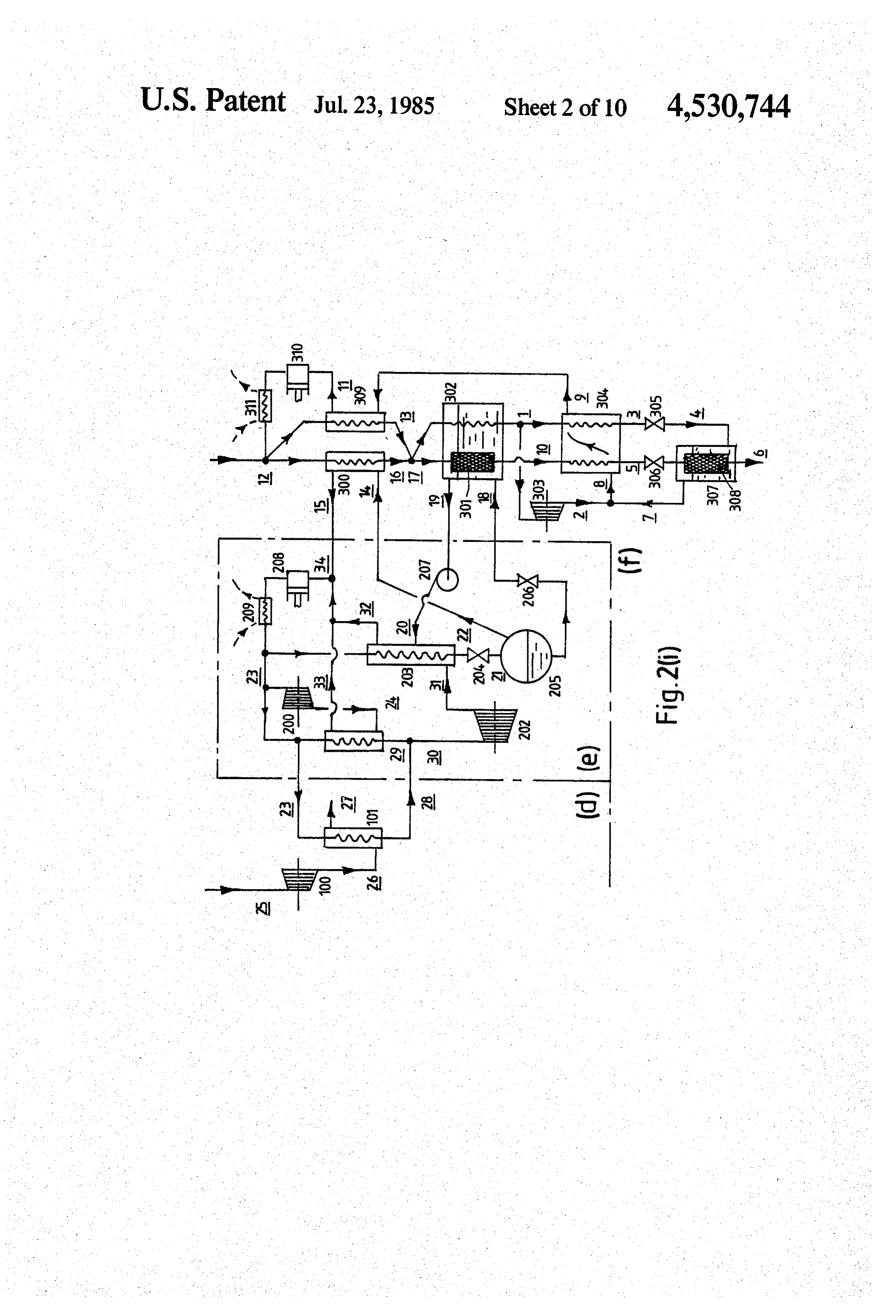
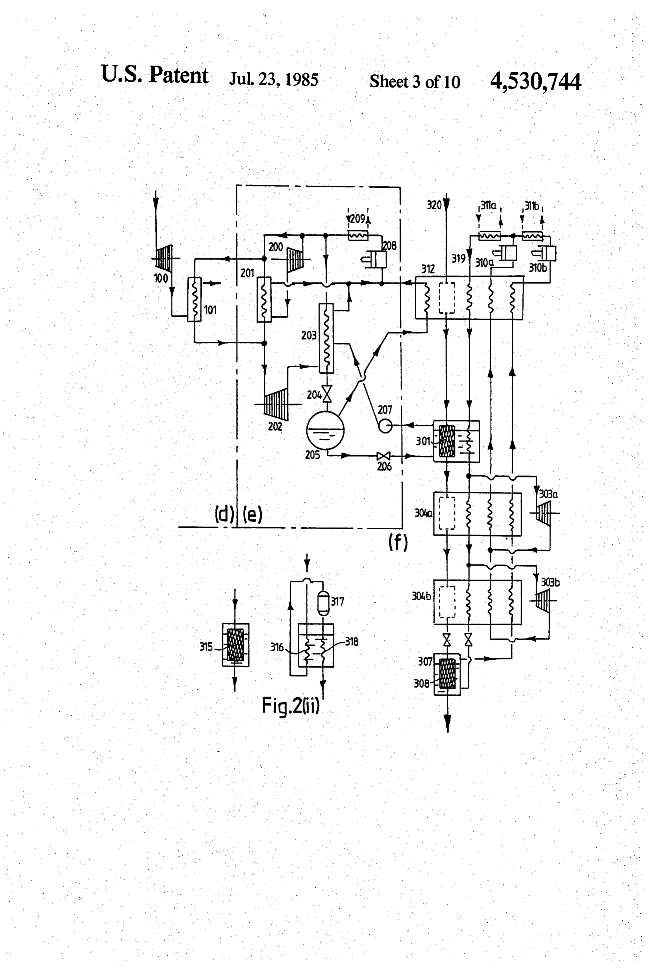
FIG. 1 is a block diagram of one embodiment of plant 60 sion turbine 100 which may be as recommended by for the production of liquid hydrogen; Swearingen J. S. (Turboexpanders and processes that FIG. 2(i) is a diagram showing details of the modules use them-Chemical Engineering Progress-Vol. 68 No. d, e and f in the embodiment of FIG. 1; 7) supplying low pressure oxygen to a heat exchanger FIG. 2(ii) is a diagram similar to FIG. 2(i) but with a 101 of either helical coiled tube configuration or alter different hydrogen liquefaction module f; 65 natively of the so-called "plate-fin' type or indeed of FIG. 2(iii) is a diagram similar to FIG. 2(i) but with a any other suitable configuration connected in the nitro different nitrogen liquefaction module e, and a different gen circuit of the nitrogen liquefaction modulee. The hydrogen liquefaction module f; oxygen passing through heat exchanger 101 is dis
Page 14
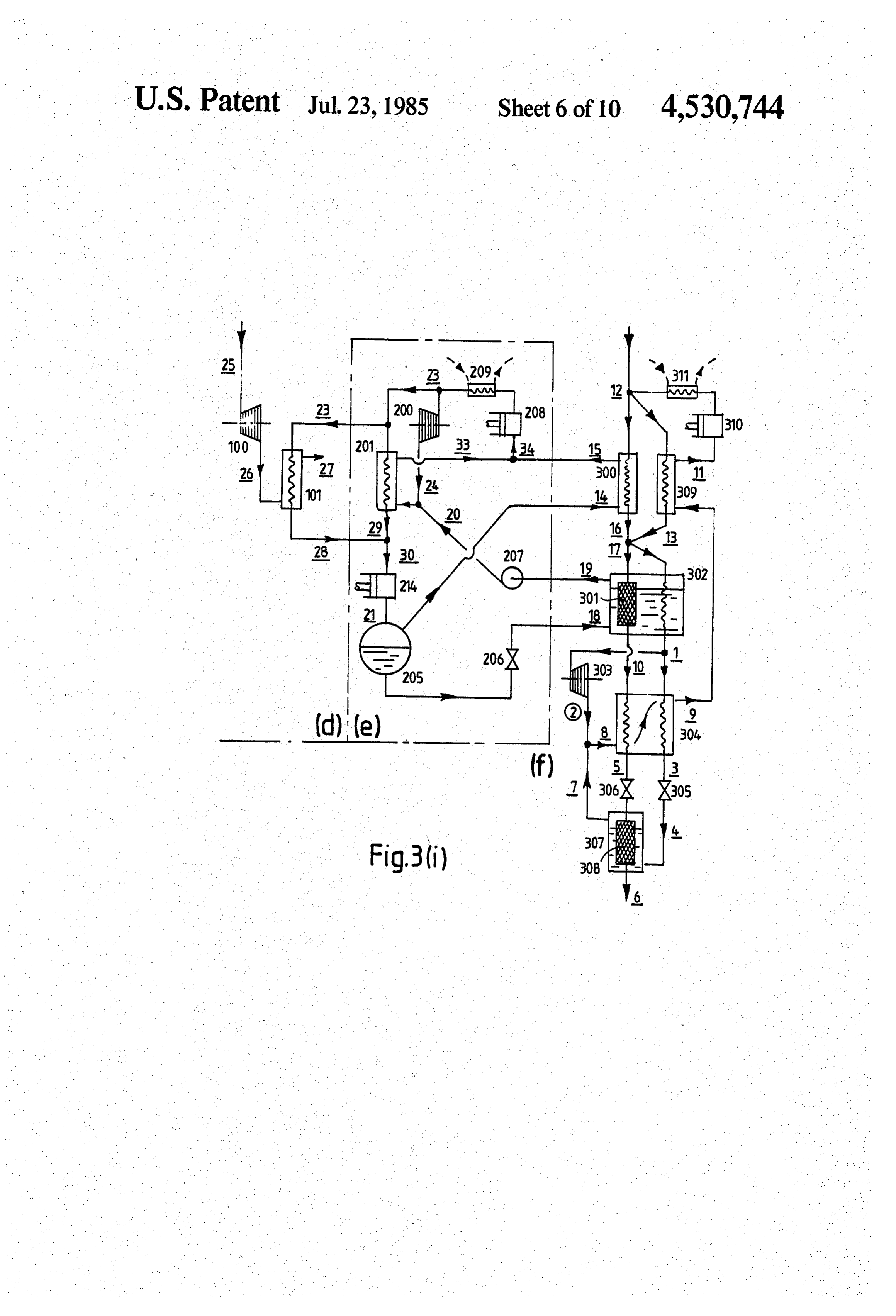
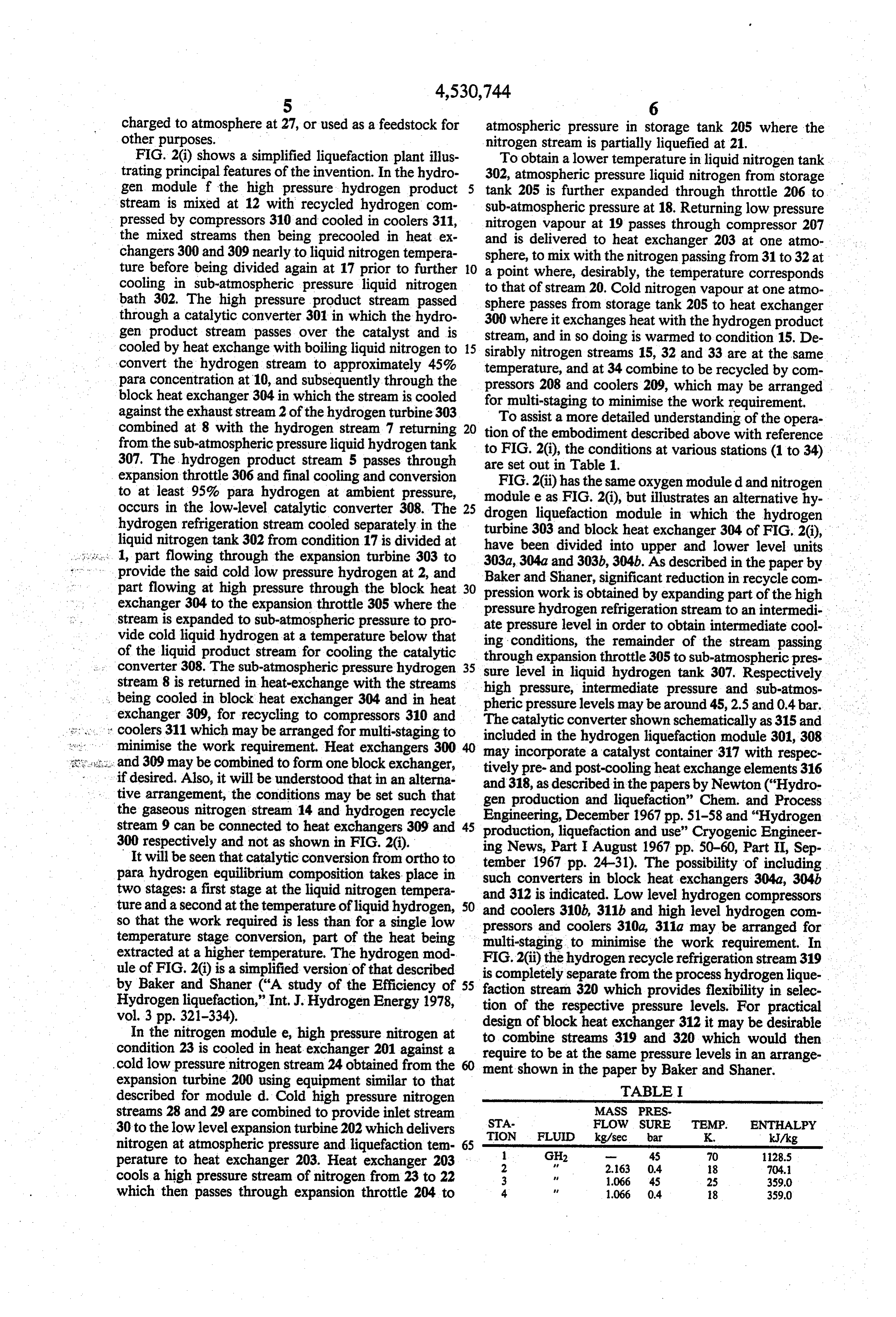
charged to atmosphere at 27, or used as a feedstock for atmospheric pressure in storage tank 205 where the other purposes. nitrogen stream is partially liquefied at 21. FIG. 2(i) shows a simplified liquefaction plant illus To obtain a lower temperature in liquid nitrogen tank trating principal features of the invention. In the hydro 302, atmospheric pressure liquid nitrogen from storage gen module f the high pressure hydrogen product tank 205 is further expanded through throttle 206 to stream is mixed at 12 with recycled hydrogen com sub-atmospheric pressure at 18. Returning low pressure pressed by compressors 310 and cooled in coolers 311, nitrogen vapour at 19 passes through compressor 207 the mixed streams then being precooled in heat ex and is delivered to heat exchanger 203 at one atmo changers 300 and 309 nearly to liquid nitrogen tempera sphere, to mix with the nitrogen passing from 31 to 32 at ture before being divided again at 17 prior to further O cooling in sub-atmospheric pressure liquid nitrogen atopoint that where, desirably, the temperature corresponds of stream 20. Cold nitrogen vapour at one atmo bath 302. The high pressure product stream passed sphere passes from storage tank 205 to heat exchanger through a catalytic converter 301 in which the hydro 300 where it exchanges heat with the hydrogen product gen product stream passes over the catalyst and is stream, and in so doing is warmed to condition 15. De cooled by heat exchange with boiling liquid nitrogen to 15 sirably nitrogen streams 15, 32 and 33 are at the same convert the hydrogen stream to approximately 45% temperature, and at 34 combine to be recycled by com para concentration at 10, and subsequently through the pressors 208 and coolers 209, which may be arranged block heat exchanger 304 in which the stream is cooled for multi-staging to minimise the work requirement, against the exhauststream 2 of the hydrogen turbine 303 combined at 8 with the hydrogen stream 7 returning 20 tionToofassist a more detailed understanding of the opera the embodiment described above with reference from the sub-atmospheric pressure liquid hydrogen tank 307. The hydrogen product stream 5 passes through to FIG. 2(i), the conditions at various stations (1 to 34) are set out in Table 1.
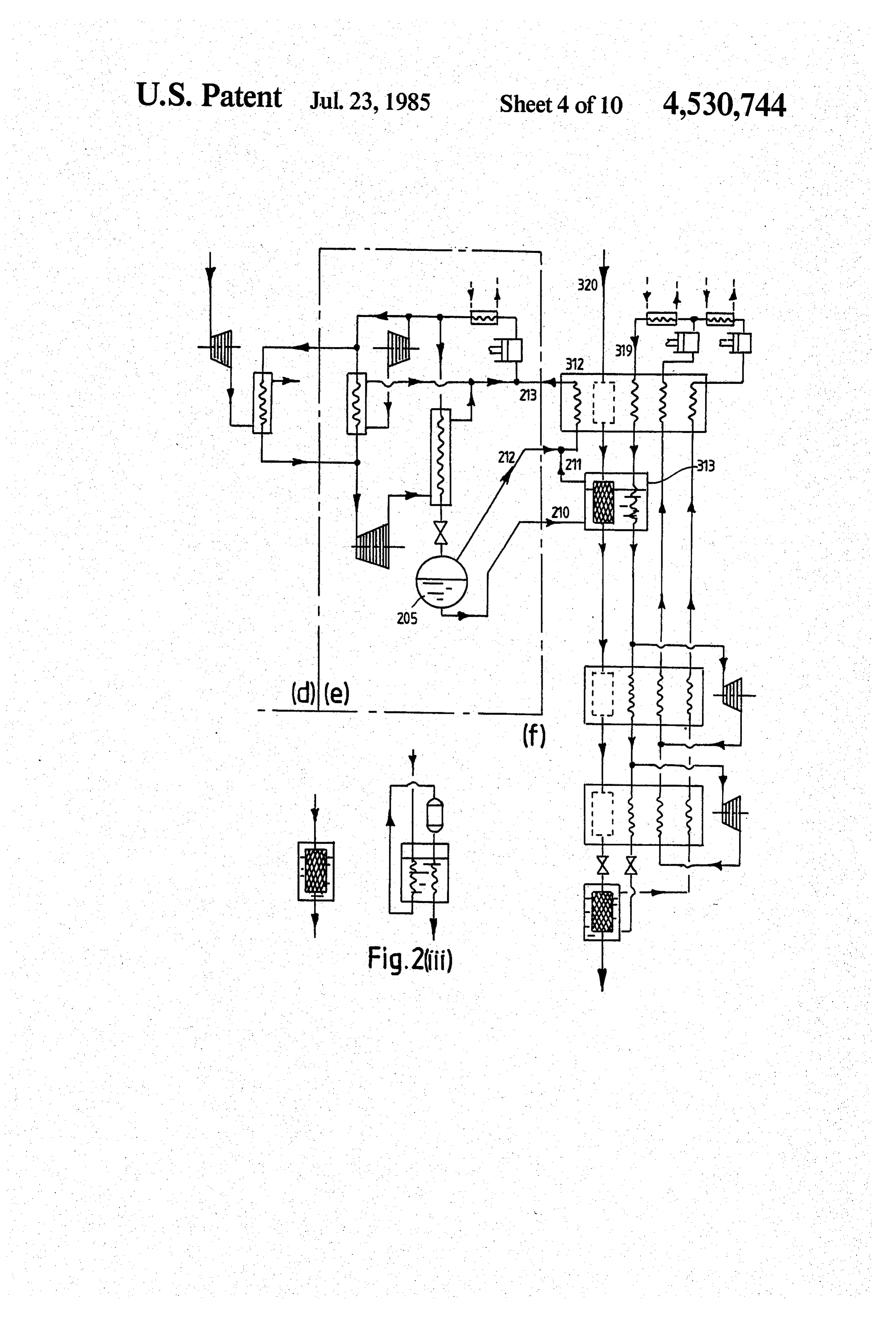
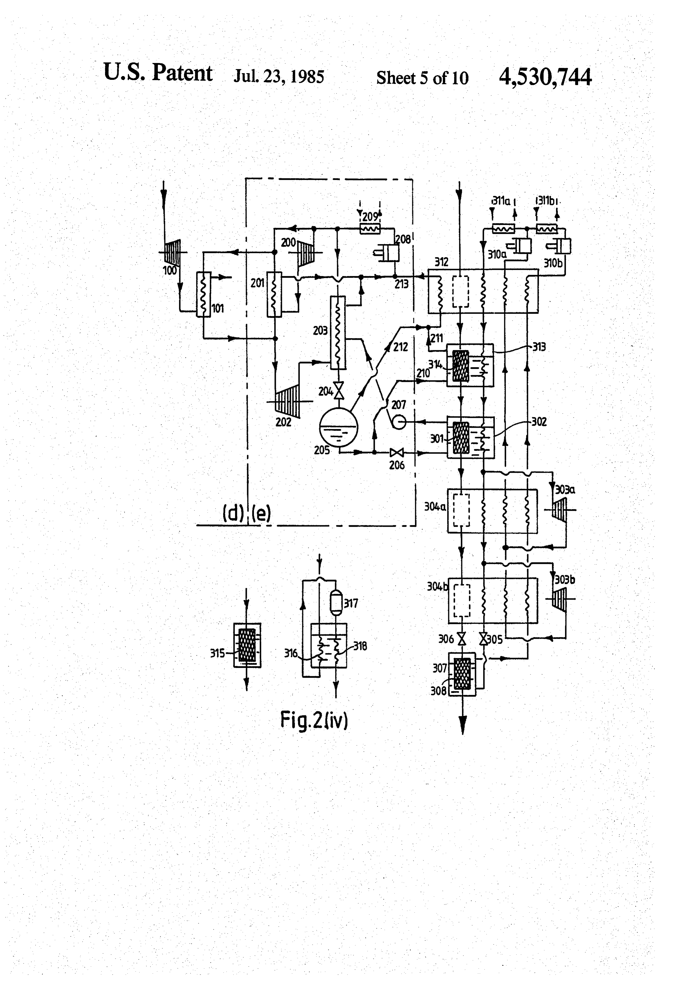
expansion throttle 306 and final cooling and conversion FIG.2(ii) has the same oxygen moduled and nitrogen to at least 95% para hydrogen at ambient pressure, module occurs in the low-level catalytic converter 308. The 25 drogen eliquefaction as FIG. 2(i), but illustrates an alternative hy hydrogen refrigeration stream cooled separately in the turbine 303 and blockmodule heat in which the hydrogen exchanger 304 of FIG. 2(i), liquid nitrogen tank 302 from condition 17 is divided at have been divided into upper and lower :... 1, part flowing through the expansion turbine 303 to 303a, 304a and 303b, 304b. As described in thelevel paper units
provide the said cold low pressure hydrogen at 2, and Baker and Shaner, significant reduction in recycle com part flowing at high pressure through the block heat 30 pression work is obtained by expanding part of the high exchanger 304 to the expansion throttle 305 where the pressure hydrogen refrigeration stream to an intermedi stream is expanded to sub-atmospheric pressure to pro ate pressure level in order to obtain intermediate cool vide cold liquid hydrogen at a temperature below that ing conditions, the remainder of the stream passing of the liquid product stream for cooling the catalytic through converter 308. The sub-atmospheric pressure hydrogen 35 sure levelexpansion throttle 305 to sub-atmospheric pres in liquid hydrogen tank 307. Respectively stream 8 is returned in heat-exchange with the streams high pressure, intermediate pressure and sub-atmos being cooled in block heat exchanger 304 and in heat pheric pressure levels may be around 45,2.5 and 0.4bar. exchanger 309, for recycling to compressors 310 and s' coolers 311 which may be arranged for multi-staging to The catalytic converter shown schematically as 315 and included in the hydrogen liquefaction module 301, 308 minimise the work requirement. Heat exchangers 300 may incorporate a catalyst container 317 with respec is and 309 may be combined to form one block exchanger, tively pre- and post-cooling heat exchange elements 316 if desired. Also, it will be understood that in an alterna and 318, as described in the papers by Newton ("Hydro tive arrangement, the conditions may be set such that gen production and liquefaction" Chem. and Process the gaseous nitrogen stream 14 and hydrogen recycle Engineering, December 1967 pp. 51-58 and "Hydrogen stream 9 can be connected to heat exchangers 309 and 45 production, liquefaction and use” Cryogenic Engineer 300 respectively and not as shown in FIG. 2(i).
It will be seen that catalytic conversion from ortho to ing tember
News, Part I August 1967 pp. 50-60, Part II, Sep 1967 pp. 24-31). The possibility of including para hydrogen equilibrium composition takes place in such converters in block heat exchangers 304a, 304b. two stages: a first stage at the liquid nitrogen tempera and 312 is indicated.
ture and a second at the temperature of liquid hydrogen, 50 and coolers 310b, 311bLow level hydrogen compressors and high level hydrogen com so that the work required is less than for a single low pressors and coolers 310a, 311a may be arranged for temperature stage conversion, part of the heat being multi-staging to minimise the work requirement. In extracted at a higher temperature. The hydrogen mod FIG.2(ii) the hydrogen recycle refrigeration stream 319 ule of FIG. 2(i) is a simplified version of that described is completely separate from the process hydrogen lique by Baker and Shaner (“A study of the Efficiency of 55 faction stream 320 which provides flexibility in selec Hydrogen liquefaction,' Int, J. Hydrogen Energy 1978, tion of the respective pressure levels. For practical vol. 3 pp. 321-334). design of blockheat exchanger 312 it may be desirable In the nitrogen module e, high pressure nitrogen at to combine streams 319 and 320 which would then condition 23 is cooled in heat exchanger 201 against a require to be at the same pressure levels in an arrange cold low pressure nitrogen stream 24 obtained from the 60 ment shown in the paper by Baker and Shaner. expansion turbine 200 using equipment similar to that TABLE I described for moduled. Cold high pressure nitrogen streams 28 and 29 are combined to provide inlet stream STA-
MASS PRES
FLOW SURE TEMP. ENTHALPY
30 to the low level expansion turbine 202 which delivers TION FLUID kg/sec bar K. kJ/kg nitrogen at atmospheric pressure and liquefaction tem 65 perature to heat exchanger 203. Heat exchanger 203 2
cools a high pressure stream of nitrogen from 23 to 22 3 1.066 45 25 3590 which then passes through expansion throttle 204 to 4. 1066 0.4 8 3590
Page 15
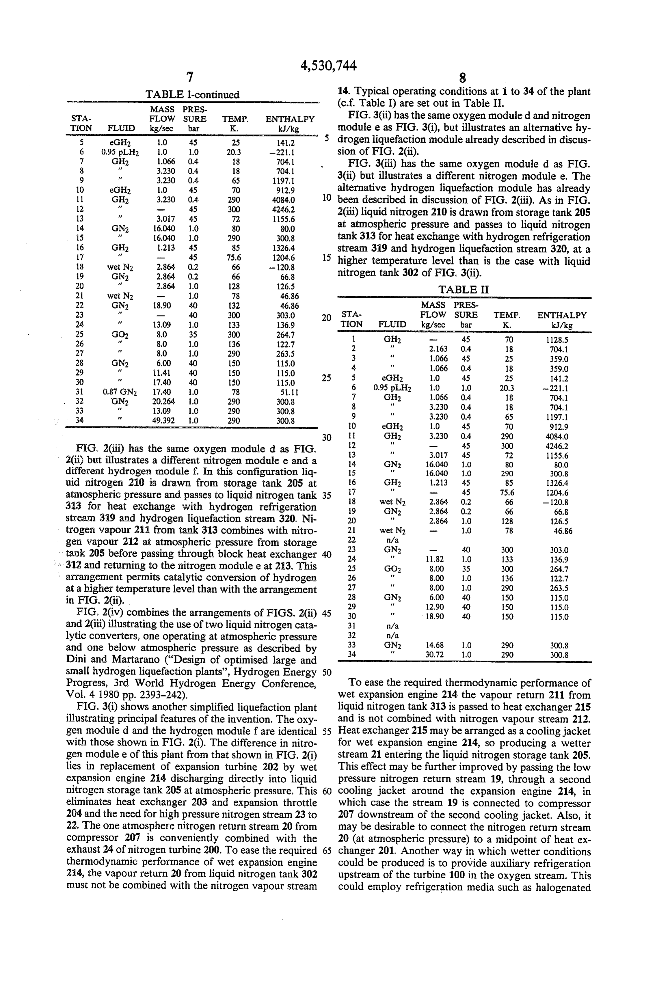
TABLE I-continued 14. Typical operating conditions at 1 to 34 of the plant MASS PRES (c.f. Table I) are set out in Table II.
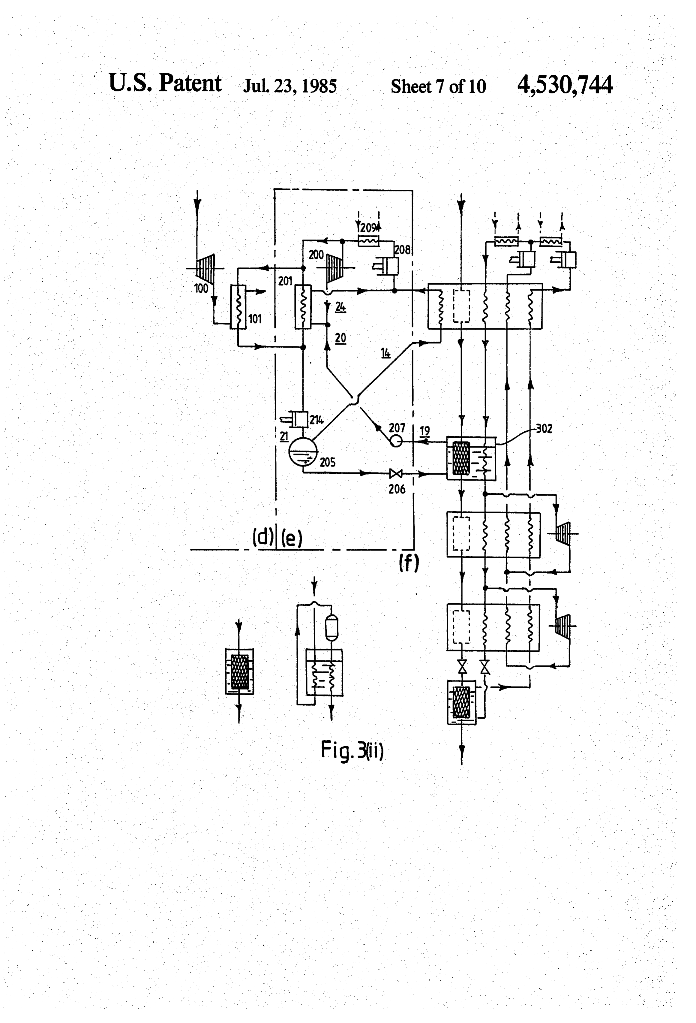
STA FLOW SURE TEMP. ENTHALPY FIG.3(ii) has the same oxygen moduled and nitrogen TION FLUID kg/sec bar K. kJ/kg module e as FIG. 3(i), but illustrates an alternative hy 5 eGH2 0 45 25 412 drogen liquefaction module already described in discus 6 0.95 plH2 1.0 1.0 20.3 -221.1 sion of FIG. 2(ii).
7 GH2 1.066 0.4 18 704.1 FIG. 3(iii) has the same oxygen moduled as FIG.
9 f 3.230 0.4 65 1197.1 3(ii) but illustrates a different nitrogen module e. The 10 eGH2 10 45 70 912.9 alternative hydrogen liquefaction module has already 10 been described in discussion of FIG. 2(iii). As in FIG.
12 45 300 4246.2 2(iii) liquid nitrogen 210 is drawn from storage tank 205
14 GN2 16.040 1.0 80 80.0 at atmospheric pressure and passes to liquid nitrogen 15 f 16.040 1.0 290 300.8 tank 313 for heat exchange with hydrogen refrigeration
stream 319 and hydrogen liquefaction stream 320, at a 15 higher temperature level than is the case with liquid
19 GN2 2.864 0.2 66 66.8 nitrogen tank 302 of FIG. 3(ii).
TABLE II
22 GN2 18.90 40 32 46.86 MASS PRES 23 m 40 300 303.0 20 STA- FLOW SURE TEMP. ENTHALPY 24 13.09 1.0 133 136.9 TION FLUID kg/sec bar K. kJ/kg 25 GO2 8.0 35 300 264.7 1 GH2 - 45 70 1128.5 26 8.0 1.0 136 122.7 2 F. 2.63 0.4 18 704.1
28 GN2 6.00 40 150 15.0 3 1066 45 25 359.0
30 17.40 40 150 115.0 25 5 eGHz 1.0 45 25 14.2 31 0.87 GN2 17.40 1.0 78 51.11 6 0.95 pLH2 1.0 1.0 20.3 -221.1 32 GN2 20,264 1.0 290 300.8 7 GH2 1.066 0.4 18 704.1 33 13.09 1.0 290 300.8 8 f 3.230 0.4 18 704.1 34 49,392 10 290 9 f 3.230 0.4 65 1197.1
FIG. 2(iii) has the same oxygen module d as FIG. 13 3.07 45 72 1155.6 20ii) but illustrates a different nitrogen module e and a 14 GN2 16.040 1.0 80 80.0 different hydrogen module f. In this configuration liq 15 F. 16.040 1.0 290 300.8 uid nitrogen 210 is drawn from storage tank 205 at 16 GH2 1.213 45 85 1326.4 atmospheric pressure and passes to liquid nitrogen tank 35 187 wet N2 2.864 0.2 45 75.6
313 for heat exchange with hydrogen refrigeration 19 GN2 2.864 0.2 66 66.8 stream 319 and hydrogen liquefaction stream 320. Ni 20 f 2.864 1.0 128 126.5 trogen vapour 211 from tank 313 combines with nitro 21 wet N2 - 1.0 78 46.86 gen vapour 212 at atmospheric pressure from storage 22
tank 205 before passing through block heat exchanger 24 11.82 1.0 133 136.9 i r312 and returning to the nitrogen module e at 23. This 25 GO2 8.00 35 300 264.7 arrangement permits catalytic conversion of hydrogen 26 fe 8,00 1.0 136 122.7 at a higher temperature level than with the arrangement 27
in FIG. 2(ii). 29 AF 12.90 40 50 115.0 FIG. 2(iv) combines the arrangements of FIGS. 2(ii) 45 30 p 18.90 40 50 115.0 and 2Ciii) illustrating the use of two liquid nitrogen cata 31 n/a lytic converters, one operating at atmospheric pressure 32
and one below atmospheric pressure as described by 34 AA 30.72 1.0 290 300.8 Dini and Martarano ("Design of optimised large and small hydrogen liquefaction plants', Hydrogen Energy 50
Progress, 3rd World Hydrogen Energy Conference, To ease the required thermodynamic performance of Vol. 4 1980 pp. 2393-242). wet expansion engine 214 the vapour return 211 from FIG. 3(i) shows another simplified liquefaction plant liquid nitrogen tank 313 is passed to heat exchanger 215 illustrating principal features of the invention. The oxy and is not combined with nitrogen vapour stream 212. gen moduled and the hydrogen module fare identical 55 Heat exchanger 215 may be arranged as a cooling jacket with those shown in FIG. 2(i). The difference in nitro for wet expansion engine 214, so producing a wetter gen module e of this plant from that shown in FIG. 2(i) stream 21 entering the liquid nitrogen storage tank 205. lies in replacement of expansion turbine 202 by wet This effect may be further improved by passing the low expansion engine 214 discharging directly into liquid pressure nitrogen return stream 19, through a second nitrogen storage tank 205 at atmospheric pressure. This 60 cooling jacket around the expansion engine 214, in eliminates heat exchanger 203 and expansion throttle which case the stream 19 is connected to compressor 204 and the need for high pressure nitrogen stream 23 to 207 downstream of the second cooling jacket. Also, it 22. The one atmosphere nitrogen return stream 20 from may be desirable to connect the nitrogen return stream compressor 207 is conveniently combined with the 20 (at atmospheric pressure) to a midpoint of heat ex exhaust 24 of nitrogen turbine 200. To ease the required 65 changer 201. Another way in which wetter conditions thermodynamic performance of wet expansion engine could be produced is to provide auxiliary refrigeration 214, the vapour return 20 from liquid nitrogen tank 302 upstream of the turbine 100 in the oxygen stream. This must not be combined with the nitrogen vapour stream could employ refrigeration media such as halogenated
Page 16
hydrocarbons, propylene or ethylene, similar auxiliary hydrogen product stream and an oxygen stream both refrigeration may be provided in the nitrogen module e under pressure, a hydrogen liquefaction module receiv at inlet to the nitrogen turbine 200, in which case the ing a stream of hydrogen under pressure from the elec nitrogen return stream 20 is connected to a midpoint of trolysis means, an oxygen module receiving a stream of heat exchanger 201 as described above. oxygen under pressure from the electrolysis means and FIG. 3(iv) combines the arrangements of FIGS. 3(ii) including an expansion means connected to the oxygen and 3(iii). stream for supplying low temperature and low pressure FIG. 4 illustrates a different configuration of the oxygen to a heat exchanger in a buffer cooling circuit modules d, e and f in which reversed Stirling-cycle connected between the hydrogen liquefaction module liquefaction machines 410 and 412 are used in both the 10 and the oxygen module and comprising a closed circuit nitrogen module e and the hydrogen module f. These refrigeration system for an inert medium including a reversed Stirling-cycle machines may be as described in heat exchanger in which the inert medium is cooled "A gas refrigerating machine for temperatures down to against low pressure oxygen received from the expan 20 K. and lower' G. Prast (Philips Technical Review. sion means, wherein the hydrogen liquefaction module 1965, Vol. 26 No. 1, pp. 1-11). 15 includes first and second heat exchangers in which the To provide replenishment nitrogen for module e and hydrogen product stream is cooled against the inert nitrogen for pressurisation of gas bearings in the oxygen medium and the buffer cooling circuit comprises wet . expansion turbine 100 it may be preferable to provide a expansion means for liquefying part of an inert medium separation plant as is known perse, in addition to appa liquefaction stream, and connected to supply the first ratus described above. 20 heat exchanger with gaseous inert medium from the wet I claim: expansion means and to supply the second heat ex 1. A method of producing liquid hydrogen compris changer, downstream of the first heat exchanger in the ing electrolysing water under pressure to generate sepa hydrogen liquefaction module, with liquefied inert me rate streams of oxygen and hydrogen gas under pres dium, a return flow of inert medium from the second sure, removing heat from the hydrogen stream during 25 heat exchanger being connected to flow through a third liquefaction thereof by heat exchange with an inert heat exchanger supplying the wet expansion means so as medium flowing in a separate closed cycle buffer cool to cool at least a part of the inert medium liquefaction ing circuit, and expanding the oxygen stream in an ex stream against the said return flow. pansion means to produce cooling for the inert medium 8. Apparatus according to claim 7 wherein down buffer cooling circuit, passing an inert medium liquefac 30 stream of the connection between the buffer cooling tion stream through wet expansion means to liquefy circuit and the hydrogen liquefaction module, the hy some of the inert medium, cooling the hydrogen prod drogen liquefaction module comprises further cooling uct stream in a first heat exchange stage against the means for the hydrogen product stream. gaseous output of the wet expansion means and in a 9. Apparatus according to claim 8 wherein the said second heat exchange stage against the liquefied inert 35 further cooling means comprises at least one refrigera medium and cooling at least a part of the inert medium tion stage connected for cooling the hydrogen product liquefaction stream flowing to the wet expansion means stream against a refrigerant.
against a return flow of inert medium from the second 10. Apparatus according to claim 9 wherein the re heat exchange stage. frigeration stage is connected in an open cycle refrigera 2. A method according to claim 1 wherein following 40 tion system in which the refrigerant is hydrogen tapped cooling against the inert medium, the hydrogen product from the product stream.
stream is cooled further against liquified and/or gaseous 11. Apparatus according to claim 9 wherein the re hydrogen tapped from the product stream in an open frigeration stage is connected in a closed cycle refriger cycle hydrogen refrigeration system. ation system; the refrigerant being selected from helium 3. A method according to claim 1 wherein following 45 and hydrogen.
cooling against the inert medium, the hydrogen is 12. Apparatus according to claim 8 wherein the said cooled further against the refrigerant in a closed cycle further cooling is effected by a plurality of refrigeration refrigeration circuit, the refrigerant being selected from stages and comprising an expansion device connected hydrogen and helium. between successive stages for expanding the refrigerant 4. A method according to claim 2 wherein the said 50 flowing therebetween.
further cooling is effected in stages and wherein the 13. Apparatus according to claim 9 wherein at least a refrigerant stream is expanded between the said stages. final refrigeration stage comprises a catalytic converter. 5. A method according to claim 1 wherein during 14. Apparatus according to claim 7 wherein the liquefaction of the hydrogen product stream, the stream buffer cooling circuit comprises compression means is at least partially converted to para- hydrogen by 55 receiving gaseous inert medium from the said first heat passing the stream through at least one high tempera exchanger, the return flow of inert medium from second ture level catalytic converter and at least one low tem heat exchanger being connected to flow to the compres perature level catalytic converter. sor via a third heat exchanger, connected in the inert 6. A method according to claim 1 wherein a part of medium liquefaction means for cooling at least some of the inert medium liquefaction stream is cooled against 60 the inert medium liquefaction stream against the said the said return flow, in parallel with heat exchange return flow.
between the remainder of the inert medium liquefaction 15. Apparatus according to claim 14 wherein the low stream and the low pressure oxygen stream. pressure oxygen/inert medium heat exchanger, is con 7. Apparatus for the production of liquid hydrogen in nected in parallel with the third heat exchanger and which, during liquefaction of the hydrogen product 65 cools the remainder of the inert medium liquefaction stream, heat is removed therefrom by heat exchange stream.
with an inert medium, comprising apparatus for the 16. Apparatus according to claim 14 and comprising electrolysis of water under pressure to produce the a fourth heat exchanger connected between the said
Page 17
second and third heat exchangers to receive the return a flow of inert medium from the second heat exchanger fourth heat exchanger is in the form of a cooling jacket for heat exchange against the inert medium liquefaction around the wet expansion means. Strea.
17. Apparatus according to claim 16 wherein the 5
Provenance
- Collection
- Cited prior art
- Original PDF
- patentimages.storage.googleapis.com →
- Filed
- 1984-03-09
- Pages
- 17
- Method
- pdftotext (the PDF's own text layer) + pdftoppm 300dpi page scans
- Source
- Google Patents bibliographic record
- Granted
- 1985-07-23
- Inventors
- Eric M. Smith
- Transcribed from
- patentimages.storage.googleapis.com →