patent · US2585882
Danger detecting means for gas distributing systems
12 February 1952
Page 1
Drawing sheet — no readable text.
Page 2
Drawing sheet — no readable text.

Page 3
Patented Feb. 12, 1952 2,585,882
- UNITED STATES PATENT OFFICE
DANGER BETECTING MEANS FOR GAS
: DISTRIBUTING SYSTEMS
George L. Weissman and Howard A. Graffis, De troit, Mich.; said Grafis assignor to said Weiss
: Application: October 12, 1945, Serial No. 621,924
* The invention relates to apparatus for use in : connection with gas distributing systems and itions of the same and their functions given be allow.
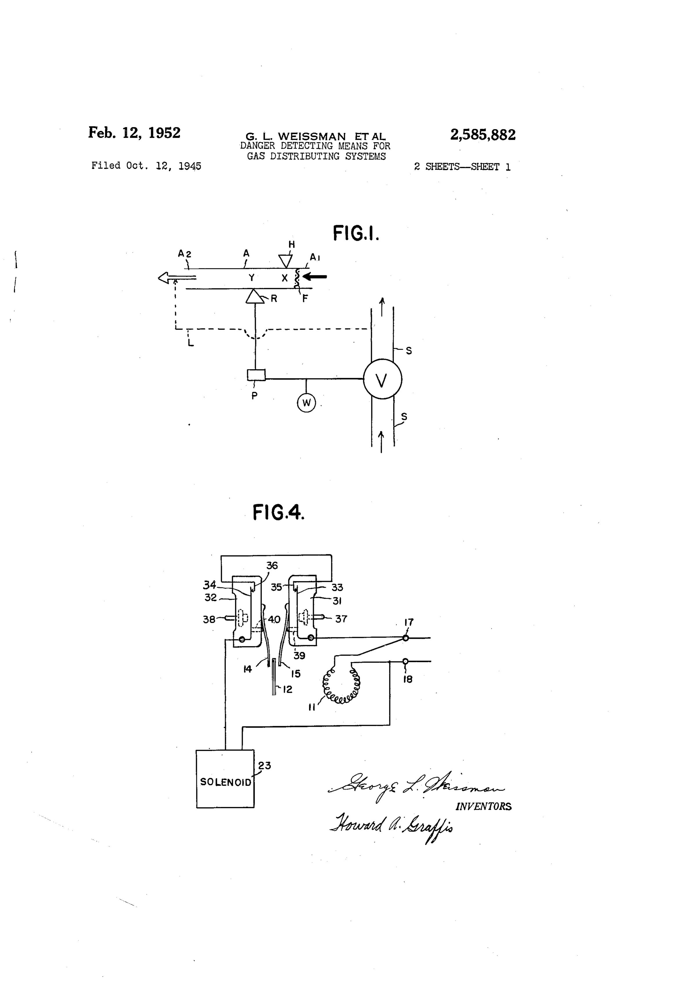
it is the primary object of the invention, to-de- Fig. 1 of the drawings is a functional diagram ...tect danger. or possible danger in the operation, wherein the symbols represent general means iIt is a further object to provide detecting means 5 and their functions, rather"than any particular for the presence of an inflammable, mixture of form of apparatus, thereby clarifying the com -air tand-gas in a selected area, also for detecting plete new warning and flow controlling process failure: of gas pressure in the supply system which and the interrelationships of the various steps . . night, resuit in is the extinguishing of a gas therein; Fig. 2 an elevation, showing a preferred -burner. With the subsequent escape of gas there- 10 embodiment of apparatus for carrying out the i.from. flow controlling process, which is largely in cross Still-further...it is an object to detect any in- section, but having limited portions of the figure ..operative condition in the detecting apparatus around the centrally located thermoresponsive . . which would cause failure in operation thereof. part appearing in full open view; Fig. 3 an en It is a further object to utilize the detection lis-larged detail in cross-section of the bi-metallic means: either for warning of possible danger or ...thermoresponsive element and switch members * for the actual cutting-off of the gas supply there- cooperating therewith taken along line 3-3 of by eliminating the danger. Fig. 2;-and-Fig. 4 is a wiring diagram showing : The above and other. objects are realized in the electrical connections used with the ap :accordance with the present invention by passing 20, paratus of Fig. 2 and is particularly usefullbe a current of gas taken from the atmosphere of a cause it shows the internal wiring of the switch t-selected: space which may be suspected of con- sbox of Fig.2 and also serves to illustrate the mode ::taining a dangerous explosive, or near, explosive : of operation of the two norfinally closed, Single : mixture of gases, through a flash-back arrester pole, single throw, maintained-contact type micro into and through an ignition chamber enclosed 25-switches equipped with manual reset pins' which s, away from the selected space, first-passing the are contained in the switchbox of Fig. 2. current of gas within said chamber...into contact .-In-the functional diagram of Fig. 1 there are 2 with and past a normally functioning source of shown a main supply line Sfor combustible gas, heat within said chamber whereby the gases of a warning device Wand/or a controlling means r said current are normally brought to a tempera-3.0 W for giving a warning signal or actually con ture at least great enough to ignite any ignitable trolling the supply of said gas, and inserted in mixture contained therein and cause it to burn, . . line-Sifa, controlling means but either entirely sand then-carrying the resulting current of nor- separate from line Sor connected therewith, as mally heated gases into contact with and past desired, if a. warning device'W means, a cham itemperature responsive means attached to said 35 ber-A. having an inlet A1 for the gas at one chamber whereby a source of power for a warning end thereof and an outlet A2 spaced a convenient s device or, preferably, a source of power for a distance from inlet A1 to form an ignition cham gasflow controlling device operatively connected ber within chamber-Alarge enough to accommo to the main supply line of a combustible gas, . . date a flashback arrester F a heat supplying is put into operation in response to predeter-40 region X and a heat transfer space Yon the op ...mined changes, increases or decreases, in the positeside of region X from arrester F, a heat ...temperature of said normally heated gases. The is source H. opposite region X for heating the same - method is especially valuable because it not only . and also igniting combustible gas mixtures flow functions to positively eliminate danger before sing through chamber A, a means R, located op an explosive mixture develops, or as soon as such. 45 posite: space Y and responsive to temperature : a mixture is present, but also gives warning or - changes therein so as to actuate a source of power automatically shuts off a combustible gas supply t-and-danger detecting device P which is oper whenever the heat-source used in... the method statively-connected to means R and actuates the ... fails. same to automatically produce movement or The novel means and apparatus combinations 50 proper functioning of warning and/or controlling - described herein are especially suitable for use means V corresponding to said temperature i. in the: above mentioned: new method-of-warn- (-changes.
::ing or of control of a combustible gas supply. The-arrows at inlet Ai-and-outlet A2 indicate di The invention will be-understood by reference rection of gas-flow-caused by pressure at the : to the accompanying drawings and the descrip- 55:right of-the-arrows or suction at the left. and
Page 4
ahead of the arrows, or by combination of the on the delivery Side of controlling means W, as pressure and suction. Means for producing the indicated by dotted line L, the method is espe pressure and/or suction with consequent flow cially efficient because the pilot burner (a poten of gas through. A may consist of any of the con tial means for igniting explosive mixtures) not ventional or known means for so operating. only goes out When the main gas Supply is shut However, in the preferred method, the gas flow off at controller V, but controller V itself is auto producing means for chamber A is operative by matically made to shut off the supply whenever Virtue of noimally continuous preSSure in line the pilot burner is blown out or otherwise ex S on the delivery Side of a valve W inserted in tinguished While controller W is still open or in the “on' position. This latter action occurs
S which is tranSraitted to and Serves to operate 10 because said gas flow producing means. This is indicated the unburned gases eScaping at the ex by dotted line I of Fig. 1, but is more clearly tinguished pilot burner are carried into and illustrated by the embodiment of the invention burned in chamber A and then drawn past Space as shown in Fig. 2 Where a venturi or jet located Y, thereby producing the necessary temperature back of a pilot is connected to the main gas 5 increase in Space Y to cause the main supply supply line on the delively side of the main gas to be shut off. This action can be made to Oc Supply line valve and is used to produce Suction cur more quickly and more Certainly by having and hence itioW of gas through the ignition inlet A1 of A near the pilot burner or directly chambei and past the heated Wire filament. connected by a pipe to a point very near to the At least a general idea of the operation of the 20 pilot burner.
Actual operation of the method and especially method of the present invention can be under the preferred method, as well as new and novel stood by reference to Fig. 1. Thus, when there apparatus useful for carrying out the preferred are no leaks in the gas Supply System of Which the main supply line S is shown, and when there method, can be even better understood by refer ence to Fig. 2 with reference to Figs. 3 and 4 is adequate combustion of gas at delivery points Where necessary.
of the system and no gases or flammable vapors Fig. 2 ShoWS a pipe , which supplies combusti from any Source whatsoever are being released ble gas, taken from the delivery side of the main andd drawn into chamber A, the flow through gas supply line valve 24, to a jet 3 which sup chamber. A consists mainly of ordinary air, With perhaps a Small percentage of burned gases in 30 plies gas through pipe 2 to a conventional pilot light, not shown. Flow of the gas through the those instances Where gas from Supply line S is jet 3 located in T-connection 4 produces suc being burned outside of chamber A for normal heating or power purposes. Under Such normal tion in the ignition or combustion chamber con circumstances, there is a constant supply of heat sisting of fire-resistant nipples 5 and 6 and T Connection 7, thereby sucking gases into said by source H and also a constant and continuous 35 transfer of heat from region X to Space Y with chamber through tubes 8 and 9 fitted into the no appreciable temperature fluctuations in Space cap 25 that is fastened onto the outer end of Y, since the flow of air through A is also Sub nipple 6 in an airtight manner. stantially constant. Now any one or all of SeW Tube 8 can be of short length because pipe eral dangerous circumstances can arise but the 40 the2 is customarily short for a pilot burner and method diagrammed in Fig. 1 will promptly and flame of the pilot burner at its upper end is automatically operate to remove the danger of therefore fairly near to cap 25. However, it is fire and explosion by completely shutting of preferred that the end of tube 8 extend to a point Very near to the pilot flame and not more than the Supply of gas in line S. an inch or two away from the flame, so that If there is a failure of heat supply means H the entire apparatus will function quickly in case there will be a decrease in temperature in Space the pilot flame is accidentally blown out. Only Y which will cause temperature responsive means One tube, Such as tube 8, carrying atmosphere R to actuate device P to shut off the supply at from the Space in the immediate vicinity of the Controlling means W.
If a leak occurs in the vicinity of chamber A, 50 pilot flame is necessary for operation of the method when using the apparatus of Fig. 2.
the combustible gas and air mixture formed will be forced through chamber A and ignited by Nevertheless, tube 9 is also shown, since a plu the high temperature in heat Supplying region rality of tubes leading from different selected X, the additional heat of the resulting combus Spaces other than that near the pilot flame can tion causing a temperature increase in Space Y 55 also be present. For example, tube 9 can lead which likewise automatically causes temperature from a point near a main burner for gas derived responsive means R, to actuate device P to shut from the main supply line. Since the volume of off the gas supply at controlling means W. Con gas flowing through a main burner is ordinarily duits or pipes can be used to conduct gases Or much greater than that flowing through the pilot, flammable vapors from distant points up to 60 the preferred and Safest apparatus is that hav chamber A, so that the method operates as a ing tubes passing through cap 25 that not only result of the presence of dangerous mixtures of carry atmosphere from near the pilot flame but air or like oxidizing gas with combustible gaS from all other points where combustible gas is or flammable vapors at places located remote being delivered which could be ignited by the from chamber A and even when combustible 65 pilot flame or like source of heat.
gases or vapors of different chemical composi It is of course to be understood that instead of tion from that in line S are present or When they having separate tubes leading to the ignition are derived from sources not connected in any chamber from each selected space intended to Way with the gases in supply line S. influence operation of the shut-off method dur In the preferred method where gases are 70 ing periods of danger, one can provide a minimum caused to flow through the ignition chamber by of only one tube, such as tube 8, which is virtue of normally continuous gas pressure on branched in any desired manner to bring at noSphere from the vicinity of one or more pilot the delivery side of the main supply valve or flames regulator, such as where a Venturi-backed pilot and also at the same time from one or burner is burning and is connected with line S 75 more burners. The single delivery tube, such as
Page 5
8, can also have a branchor some of its branches :as ionother pages of this catalog and in United extending to the open-air of rooms, or other 3States Patent No. 1960,020 spaces, not located close...to a regular. delivery ...Fig. 4 illustrates the normally, closed micro point for the combustible gas. Switch-Solenoid series: circuit in parallel with the - An airtight. Switchbox fo is shown in Fig. 2 electrical, heating resistor () circuit. When and is Screwed into the T-connection 7 in an air temperature changes cause the free end of bi tightmanner. Inside of Switch box. Othere are metallic element 2 to press, against tip 4. Or two Spring leaf actuated. Snap action switches, 5, plunger, 39. Or 40 is depressed and causes not shown in Fig. 2 but represented: diagram Snap. action breakage of electrical contact be -matically in the... wiring diagram of Fig. 4. . . The O tWeen contact points 34 and 35 or between con SWitches have manual reset buttons which are Stact points 34, and 36. Regardless ; of which Coperated in airtight manner through the walls of contact is broken, or if both, are broken, the switchbox. 0 by means of front screw 2, shown series circuit is thereby broken and current in Fig. 2, and a like back screw, not shown, : ceases to flow through the Solenoid. This failure -located on the other side of switchbox. 0 from of current to, flow causes the valve operator .23 . Screw 2. Terminals for the two switches, which to close valve 24 of Fig. 2. When contact between are connected...electrically in series, are shown points 33 and 3 or points 34, and 38 is broken, at 9 and 20... Cap .22 is screwed onto switch it stays broken until contact is made again manu ...box 0, after the Switches are installed and this ally by means of reset pins 3 or 38 or both, as serves to make said switchbox substantially air- : Will be required to conpete the circuit. The re ...tight. made contact will, however, immediately . . be , Electrical heating resistor connected to a broken, unless the thermo'esponsive element 2 Source...of electrical power at points 7 and 8 is kept between tips A and 5 and is not exerting Supplies...heat which is transmitted at least in pressure on either tip. So also when the valve part to bimetallic...thermoresponsive element. 2 5 : operator 23 closes Valve 24, the latter Will stay Which is normally kept at a more, or less uniforn closed until the operator is manually reset in the temperature.causing its free movable end to hold open or 'on' position again. a substantially, constant normal position mid way between the tips 4 and if 5 of the spring Cycle of operations leaf actuators of the two, snap action switches. 30 A complete cycle, from the setting of the Bimetallic element 2...is rigidly mounted or fixed apparatus into operation, through the final shut - in the streamlined support 3 attached to T offstage and up to the point Where the apparatus connection . Although thermoresponsive ele is again ready for operation, Will now be de ment, 2...is referred to as being "bimetallic,' this scribed. With reference to Fig. 2, 3 and 4. termis intended to include any equivalent ele 35 ASSunning that main gas Supply, line Valve.24 is ment made up of strips of closely adhering metals open...and maintained in that position in conse shaving differing coefficients of expansion whether quence of current flowing continuously through ...two or more metals or two- or-...more strips are the solenoid of valve operator 23, the jet 3 and used.
6 is a tightly Wound, coil of wire gauze Wedged 49. outer openburner, not shown but located near the end of tube 9, will then be supplied into nipple, 6 and Serving as a flash-back ar with combustible gas, such as the artificial or rester. natural gas ordinarily used for household or com Solenoid 23 is connected electrically in series mercial heating or power purposes. he heat with the Snap action switches in Switch box ing resistor circuit is always closed and 6 volt, and this circuit is in parallel with the heating 60 cycle electric energy is supplied at terminals resistor circuit. as is more evident from Fig. 4. 7 and 8 (e. g. by an ordinary 4 Watt bell-ring - Rart 23 of Fig. 2 is intended to represent not only ing transformer) to keep the B. & S. 29-gauge an electrically operated solenoid but also the addi Chrome-A (80 nickel, 20 chronium alloy) Wire tional parts of an electromagnetically held valve (Nichrome wire) at a temperature of about 600 'operator equipped with manual reset and lo- ; C. or higher. This requires about 0.7 ampere of . . cated, external to, but in operative connection current for a 20 turn coil With 6 inch in di With, the main gaS Supply valve 24. . . Such an ameter, turns and about an 8-inch straight: Wire operator and valve combination as represented length.
: by 23 and 2 of Fig. 2 is described as an MR-1-2 The plunger of the solenoid of 23 acts merely Emanual reset valve on page 34 of Catalog No. 51 i5. as a keeper of a mechanism, that releases Strong (Fall 1941) of General Controls Co. springs inside of valve operator 23 and these In Fig. 4 there is shown the Wiring diagram close valve 24 when the current fails and allows itsed with the apparatus of Fig. 2. The current the plunger to trip, a Spring release mechanism. Supplied at terminals f and 8 is 24 volt 60 The solenoid current is therefore negligible and cycle alternating current which can for ex 60 only 0.005 watt is needed for it. After the valve an apie e brought down by a step-down trans operator and valve combination has thus closed former from the ordinary 110 volt 60 cycle cur valve 24, the combination and the springs in rent used for household purposes. ... Parts , side of operator 23 are made ready for auto 2, 4, 5 and 23 of Fig. 4 represent the heat matic operation again by manual re-setting, e. g. ring resistor, bimetallic thermoresponsive ele as described above for the MR-1-2 manual ment, two spring leaf actuator tips, and Solenoid reset valve.
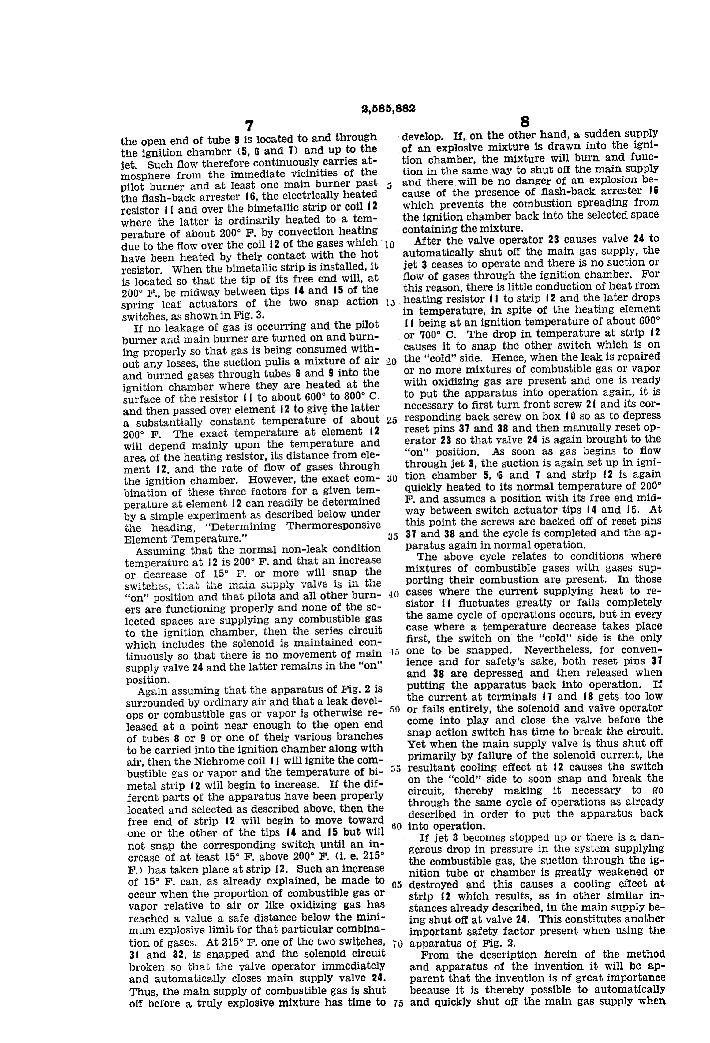
respectively of Fig. 2. The two. Snap action Due to gas pressure in pipe located on the Switches 3 and 32 are of the normally closed, delivery side of valve 24, there is flow of gas :. . single "pole, single throw, maintained-contact through the very fine orifice of jet 3 and to the type micro switches equipped, with plunger pins 70 pilot flame by way of pipe 2 and an ordinary pilot 39 and 40, and manual reset pins 37 and 38 re burner located at the upper end of pipe 2. Flow - spectively. A switch of this type is described on of gas through jet 3 produces suction or ejector page 1.07 of Micro Precision Snap Action action and flow of gas from a point near the pilot 'Switches Catalog No. 60 (1941) of the Micro flame where the open end of tube 8 is located and Switch Corporation, Freeport, Illinois, as well 5 from-a-point near the main burner flame where
Page 6
the open end of tube 9 is located to and through develop. If, on the other hand, a sudden supply the ignition chamber (5, 6 and 7) and up to the tion of an explosive mixture is drawn into the igni jet. Such flow therefore continuously carries at chamber, the mixture will burn and func mosphere from the immediate vicinities of the tion in the same way to shut off the main supply and there will be no danger of an explosion be pilot burner and at least one main burner past 5 cause the flash-back arrester 6, the electrically heated of the presence of flash-back arrester f G resistor and over the bimetallic strip or coil 2 which prevents the combustion spreading from where the latter is ordinarily heated to a tem the ignition chamber back into the selected space perature of about 200 F. by convection heating containing the mixture.
After the valve operator 23 causes valve 24 to due to the flow over the coil 2 of the gases which 0. automatically have been heated by their contact with the hot shut off the main gas supply, the resistor. When the bimetallic strip is installed, it jet 3 ceases to operate and there is no suction or is located so that the tip of its free end will, at flow of gases through the ignition chamber. For 200° F., be midway between tips f4 and 5 of the this reason, there is little conduction of heat from spring leaf actuators of the two Snap action 5 in heating resistor to strip 2 and the later drops switches, as shown in Fig. 3. temperature, in spite of the heating element If no leakage of gas is occurring and the pilot being at an ignition temperature of about 600° burner and main burner are turned on and burn or 700° C. The drop in temperature at strip 2 ing properly So that gas is being consumed with causes it to Snap the other switch which is on out any losses, the suction pulls a mixture of air the "cold' Side. Hence, when the leak is repaired and burned gases through tubes 8 and 9 into the or no more mixtures of combustible gas or vapor ignition chamber where they are heated at the With oxidizing gas are present and one is ready surface of the resistor to about 600 to 800° C. to put the apparatus into operation again, it is and then passed over element 2 to give the latter necessary to first turn front screw 2 and its cor responding back screw on box () so as to depress a substantially constant temperature of about reset pins 3 and 38 and then manually reset op 200° F. The exact temperature at element 2 erator 23 So that valve 24 is again brought to the Will depend mainly upon the temperature and area of the heating resistor, its distance from ele "on' position. As soon as gas begins to flow ment 2, and the rate of flow of gases through through jet 3, the suction is again set up in igni the ignition chamber. However, the exact com 30 tion chamber 5, 6 and 7 and strip A2 is again bination of these three factors for a given tem quickly heated to its normal temperature of 200° perature at element 2 can readily be determined F. and assumes a position with its free end mid by a simple experiment as described below under Way between Switch actuator tips 4 and 5. At the heading, "Determining Thermoresponsive this point the screws are backed off of reset pins Element Temperature.' 3 and 38 and the cycle is completed and the ap ASSuming that the normal non-leak condition paratus again in normal operation. temperature at f2 is 200' F. and that an increase The above cycle relates to conditions where Or decrease of 5° E. or more will Snap the mixtures of combustible gases with gases sup Switches, tia, the inain supply valve is in tile porting their combustion are present. In those "On' position and that pilots and all other burn () cases where the current supplying heat to re erS are functioning properly and none of the se Sistor f fluctuates greatly or fails completely lected Spaces are Supplying any combustible gas the same cycle of operations occurs, but in every to the ignition chamber, then the series circuit case where a temperature decrease takes place which includes the Solenoid is maintained con first, the Switch on the “cold' side is the only tinuously So that there is no movement of main one to be Snapped. Nevertheless, for conven Supply valve 24 and the latter remains in the "on' ience and for safety's sake, both reset pins 37 position. and 38 are depressed and then released when Again aSSuming that the apparatus of Fig. 2 is putting the apparatus back into operation. If the current at terminals 7 and 8 gets too low
Surrounded by Ordinary air and that a leak devel 5: or ops or combustible gas or vapor is otherwise re fails entirely, the Solenoid and valve operator leased at a point near enough to the open end come into play and close the valve before the Snap action Switch has time to break the circuit.
of tubes 8 or 9 or one of their various branches to be carried into the ignition chamber along with Yet when the main supply valve is thus shut off primarily by failure of the solenoid current, the air, then the Nichrome coil will ignite the com bustible gas or vapor and the temperature of bi 5 5 resultant cooling effect at 2 causes the switch On the "cold' side to soon snap and break the metal strip 2 will begin to increase. If the dif circuit, thereby making it necessary to go ferent parts of the apparatus have been properly through located and Selected as described above, then the describedthe same cycle of operations as already in order to put the apparatus back free end of Strip 2 will begin to move toward into operation.
One or the other of the tips 4 and 5 but will If jet 3 becomes stopped up or there is a dan not Snap the corresponding switch until an in gerous drop in pressure in the system supplying
the combustible gas, the suction through the ig
F.) has taken place at Strip 2. Such an increase of 15 F. can, as already explained, be made to 65 inition tube or chamber is greatly weakened or destroyed and this causes a cooling effect at occur. When the proportion of combustible gas or Strip f2 which results, as in other similar in vapor relative to air or like oxidizing gas has stances already described, in the main supply be reached a value a safe distance below the mini ing shut off at valve 24. This constitutes another nun explosive limit for that particular combina important safety factor present when using the tion of gases. At 215 F. one of the two switches, apparatus of Fig. 2.
3 and 32, is Snapped and the solenoid circuit From the description herein of the method broken. So that the valve operator immediately and apparatus of the invention it will be ap and automatically closes main supply valve 24. parent that the invention is of great importance Thus, the main Supply of combustible gas is shut because it is thereby possible to automatically off before a truly explosive mixture has time to 5 and quickly shut off the main gas supply when
Page 7
any of a large number of unsafe circumstances form. of a single loop inside. of, but not quite arise, not Only outside of the apparatus but alsotouching, the Walls of a one-half inch inside Within the apparatus itself. - diameter ignition chamber and lying in a plane which is perpendicular to the gas flow and lo
Determining thermoresponside element temper 5 cated ature . about 1% inches from element 2. If tubes 8 and 9 are bringing in air only and have
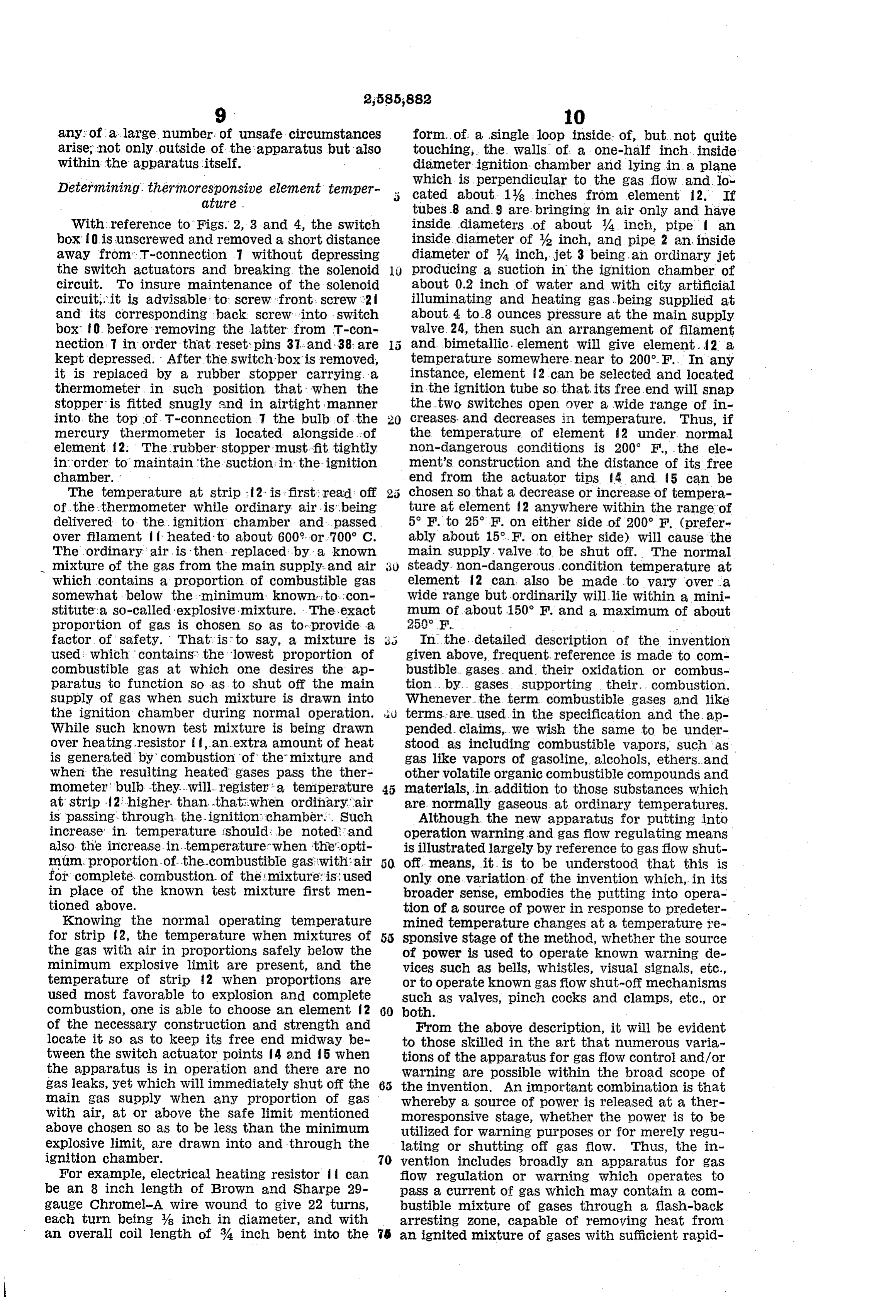
With reference to Figs. 2, 3 and 4, the switch inside diameters of about A inch, pipe? an box. Ois unscrewed and removed a short distance inside. diameter of 42 inch, and pipe 2 an inside away from T-connection 7 without depressing diameter of A inch, jet 3 being an ordinary jet the Switch actuators and breaking the Solenoid producing a suction in the ignition chamber of Circuit. To insure maintenance of the Solenoid about 0.2 inch of water and with city artificial circuit, it is advisable to screw front. Screw 2. illuminating and heating gas.being supplied at and its corresponding back Screw into . Switch about 4 to 8 ounces pressure at the main supply box f. before removing the latter from T-Con valve. 24, then such an arrangement of filament nection. 7 in order that reset; pins 37. and 38 are and bimetallic. element will give element. 2 a. kept depressed. After the switchbox is removed, temperature somewhere near to 200°F. In any it is replaced by a rubber stopper carrying. a instance, element f2 can be selected and located thermometer in such position that when the in the ignition tube so. that its free end will snap stopper is fitted Snugly and in airtight manner the two Switches open over a wide range of in into the top of T-connection 7 the bulb of the creases. and decreases in temperature. Thus, if mercury thermometer is located alongside of the temperature of element 2 under, normal element. 2: The rubber stopper must fit, tightly non-dangerous conditions is 200 F., the ele in order to maintain the suction in the -ignition ment's construction and the distance of its free chamber. end from the actuator tips 4 and 5 can be The temperature at strip ; f2 is first; read off chosen so that a decrease or increase of tempera of the thermometer while ordinary airis, being ture at element 2 anywhere within the range of delivered to the ignition chamber, and passed 5 F. to 25 F. on either side of 200° F (prefer over filament, if heated to about 600°, or 700° C. ably about 15°.F. on either side) will cause the The ordinary air is then replaced by a known main supply, valve to be shut off. The normal mixture of the gas from the main Supply. and air 30 steady non-dangerous condition temperature at which contains a proportion of combustible gas element 2 can also be made to vary over a somewhat below the minimum known to con Wide range but ordinarily will lie within a mini stitute a so-called explosive mixture. The exact mum of about 150 F. and a maximum of about proportion of gas is chosen. So as torprovide a 250°F, - factor of safety. That is to Say, a mixture is 3 In the detailed description of the invention used: Which contains the lowest proportion of given above, frequent, reference is made to com combustible gas at which one desires the ap bustible gases and their oxidation or combus paratus to function. So as to shut off the main tion ... by gases. Supporting their... combustion. Supply of gas When Such mixture is drawn into Whenever the term combustible gases and like the ignition chamber during normal operation. liu terms are used in the specification and the ap While Such known test mixture is being drawn pended claims, We Wish the same to be under over heating resistor it, an extra amount of heat stood as including combustible vapors, such as is generated by combustion of the mixture and gas like vapors of gasoline, alcohols, ethers. and When the resulting heated gases pass the ther other volatile organic combustible compounds and mometer bulb they... will. register - a temperature materials, in addition to those substances which at strip 2; higher than that:when ordinary air are normally gaseous at ordinary temperatures. is passing through-the-ignition chamber... Such Although the new apparatus for putting into increase in temperature should be noted and operation Warning and gas flow regulating means also the increase.in temperaturer when the opti is illustrated largely by reference to gas flow shut mum proportion of the combustible gas with air off means, it is to be understood that this is for complete, combustion of the imixture: is used only one variation of the invention which, in its in place of the known test mixture first men broader sense, embodies the putting into opera tioned above. tion of a source of power in response to predeter Knowing the normal operating temperature mined temperature changes at a temperature re for strip f2, the temperature when mixtures of 55 Sponsive stage of the method, whether the source the gas with air in proportions safely below the of power is used to operate known warning de minimum explosive limit are present, and the vices such as bells, whistles, visual signals, etc., temperature of strip f2 when proportions are or to operate known gas flow shut-off mechanisms used most favorable to explosion and complete such as valves, pinch cocks and clamps, etc., or combustion, one is able to choose an element 2 60 both.
of the necessary construction and strength and From the above description, it will be evident locate it. So as to keep its free end midway be to those skilled in the art that numerous varia tween the switch actuator points 4 and 5 when tions of the apparatus for gas flow control and/or the apparatus is in operation and there are no Warning are possible within the broad Scope of gas leaks, yet which will immediately shut off the the invention. An important combination is that main gas Supply when any proportion of gas whereby a source of power is released at a ther with air, at or above the safe limit mentioned mOresponsive stage, whether the power is to be above chosen so as to be less than the minimum utilized for warning purposes or for merely regu explosive limit, are drawn into and through the lating or shutting off gas flow. Thus, the in ignition chamber. 70 vention includes broadly an apparatus for gas For example, electrical heating resistor can flow regulation or Warning which operates to be an 8 inch length of Brown and Sharpe 29 pass a current of gas which may contain a com gauge Chromel-A Wire Wound to give 22 turns, bustible mixture of gases through a flash-back each turn being 8 inch in diameter, and with arresting zone, capable of removing heat from an overall coil length of 4 inch bent into the s an ignited mixture of gases with sufficient rapid
Page 8
ity to quench combustion of the same, into and stream of atmosphere is withdrawn by Said ejec through an enclosed ignition zone containing a ing meanssaid tor from selected space, a flashback arrest in Said conduit, heating means be normally functioning source of heat which first yond said flashback normally brings said current to a temperature at Said stream wheneverarrestingignitable means for igniting or raising its tem least great enough to burn any combustible mix 5 ture contained therein and then, by virtue of perature if nonignitable, a thermo responsive ele ment located in heat transferring relation to a the flow of said current of gas, normally main tains the temperature at a selected thermore portion of said stream beyond said heating means, Sponsive point located in the path of the flow O predetermined detecting and a danger element operated by a beyond the heat source at a substantially con Sive element. response of said thermo respon stant value, but said temperature at said point 2. The construction as in claim 1 in which the fluctuating away from its normal constant value thermo responsive element is normally held in by at least predetermined safe minimum in neutral position, and is operated to actuate said creases and decreases of temperature caused re danger detecting element alternatively by an in Spectively by presence of combustible mixtures in crease or decrease of temperature transmitted the original current and by failure of the nor thereto.
mally functioning source of heat to keep the tem 3. The construction as in claim 2 in which the perature at the selected thermoresponsive point danger detecting element is actuated by a pre at its normal constant value, causing heat energy 20 determined decrease of pressure of the gas at changes corresponding to said fluctuations of the Source.
temperature to operate temperature responsive 4. The construction as in claim 2 in which the power releasing means located at said point and danger detecting element is actuated by a pre utilizing the power released to operate gas flow determined drop in temperature of the heating control and/or warning means. and igniting means.
As above described the apparatus is essentially 5. The construction as in claim 3 provided with a means for detecting danger or possible danger a normally open shutoff valve for the gas supply, in connection with a gas distributing system, and means operated by the actuation of said which detecting means may be utilized either for operating an alarm or for cutting off the gas sup 30 danger detecting element for closing said shut off Waive.
ply thereby automatically preventing danger.
The dangers which can be detected are, first, the 6. The construction as in claim 3 provided with presence of an inflammable mixture of gas and an alarm, and means operated by the actuation air in Some selected space such, for instance, as of the danger detecting element for operating a room in which a gas burner is located; second, said alarm.
a drop in pressure of gas in the supply line which 35 GEORGE L. WEISSMAN. might result in the extinguishing of a gas burner HOWARD A. GRAFFIS. with subsequent leakage of gas therefrom; third, any inoperativeness of the detecting means is REFERENCES CITED detected. Thus aside from whether the appara 40 The following references are of record ill the tus is used as an alarm or for cutting off the gas file of this patent:
supply, it will always indicate danger or possible danger. UNITED STATES PATENTS What we claim is: Number Name Date 1. Means for detecting danger of the presence
within a selected space of an inflammable mix 1,681,698 Brooks ------------- Aug. 21, 1928 ture of air and gas escaping from a supply; com 2,062,605 Peters --------------- Dec. 1, 1936 prising a nozzle connected with the combustible 2,149,441 Jacobson ------------ Mar. 7, 1939 gas Supply and normally emitting a continu 2,219,391 Jacobson ----------- Oct. 29, 1940 ously flowing jet of gas therefrom, an ejector op 2,355,090 Love et al. ----------- Aug. 8, 1944 erated by the velocity of said jet, a conduit con 2,373,326 Miller ------------- Apr. 10, 1945 nected to said ejector through which a sample
Provenance
- Collection
- Cited prior art
- Original PDF
- patentimages.storage.googleapis.com →
- Filed
- 1945-10-12
- Pages
- 8
- Method
- pdftotext (the PDF's own text layer) + pdftoppm 300dpi page scans
- Source
- Google Patents bibliographic record
- Granted
- 1952-02-12
- Inventors
- George L Weissman; Howard A Graffis; WEISSMAN
- Transcribed from
- patentimages.storage.googleapis.com →