patent · US2434346
Generator burner and fuel control therefor
13 January 1948
Page 1
Drawing sheet — no readable text.
Page 2
Patented Jan. 13, 1948 2,434,346
UNITED STATES PATENT OFFICE
GENERATOR BURER AND FUE, CONTROL
THEREFOR
James L. Breese, Santa Fe, N. Mex, assignor, by mesne assignments, to Breese Burners, Inc.,
Santa Fe, N. Mex, a corporation of Delaware
Application January 15, 1944, Serial No. 518,340
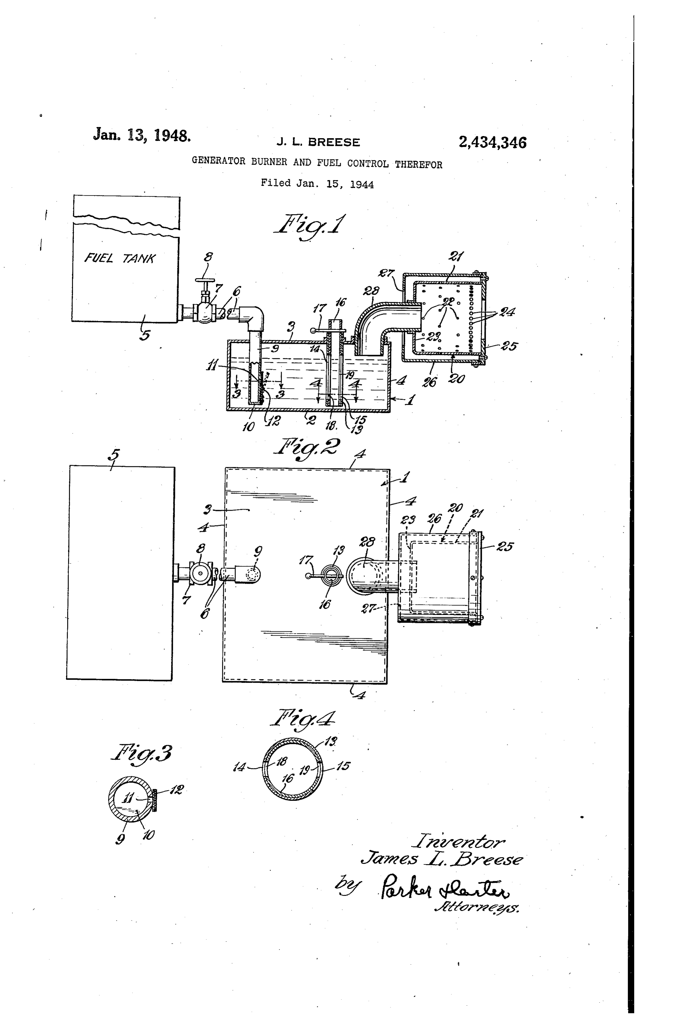
My invention relates to an improvement in va the cubic content of the vaporization chamber, porizing burners and has for one purpose to pro Thus the stored supply of fuel is kept for the vide a burner for liquid fuels, including improved most part in the tank 5, remote from the heater, fuel Storage and supply means. Another purpose and only an adequate Working head or volume is is to provide thermally actuated means for con maintained in the vaporization chamber . . trolling the fuel supply to the burner. Other In vaporizing burners of the present type the purposeS Will appear from time to time in the liquid fuel is vaporized in the vaporization cham course of the specification. ber and is carried, in vapor form, to the area of I illustrate my invention more or less diagram use. In order to maintain adequate and control natically in the accompanying drawings in which lable air supply for the vaporization chamber I Figure 1 is a vertical section; employ the structure below described. 3 is a Figure 2 is a plan view; fixed outside tube extending downwardly through Figure 3 is an enlarged section on the line 3-3 the top partition 3. It is herein shown as having of Figure 1; and generally diametrically opposed slots 4, 5, the Figure 4 is an enlarged section on the line 4-4 slot 5 being of substantially greater width than of Figure 1. the slot 4. 6 is an open topped inner tube ex Like parts are indicated by like symbols tending downwardly into the open top of the throughout the Specification and drawings. Re outer tube 3. It is provided with a handle and ferring to the drawings, generally indicates a linit member 7 which permits it to be rotated Vaporization chamber member having a bottom 20 manually and which also limits its downward Wall 2, a top Wall 3 and side walls 4. The cham penetration into the tube 3. The inner tube 6 ber is shown as rectangular in plan, but can be of is also provided with generally diametrically op any other Suitable shape. 5 indicates a fuel stor posed slots 8, 9. In the form herein shown, as age tank which may be more or less remote from Will be clear from Figure 4, the slots f8 and 9 the vaporization chamber f. It is connected 25 are the same width as the slot 4 but are of sub therewith by a fuel supply pipe 6. Any desired stantially less Width than the slot 5. When the means may be employed for closing the pipe 6 parts are in the position shown in Figure 4, a and I illustrate for example the manual operable maximum inflow of air is permitted. A clockwise valve assembly With its manually controlled movement of the inner tube f6, referring to the member 8. The pipe 6 is shown as having a ter 30 position of the parts in Figure 4, will be effective Ininal portion 9 extending downwardly through to close the slot 4 by putting the slot f8 out of the top of the wall 3 and terminating with a register with it. However, the slot 9 may still closed bottom 9 adjacent the bottom Wall 2 of be in full register with the larger slot 5. Thus the vaporization chamber. f is a liquid fuel the air Supply will be cut in half. A sufficient escape aperture. It may be controlled by means 35 rotation of the inner tube 6 in a clockwise direc Operating in response to changes in temperature. tion WOuld eventually cut of the air Supply alto illustrate for example a Warping bar 2 mount gether. It will thus be clear that I provide easy ed upon a lower portion of the pipe 9. It will be and efficient means for varying the air supply at understood that at a normal temperature range Will.
the Warping bar remains in the closed position 40 Assune that vaporizing combustion is main in which it is shown in full line in Figure 1. As tained in the vaporization chamber , it will be the level of fuel in the generator chamber drops, understood that the result is to vaporize the liq the Warping bar is subjected increasingly to the uid fuel. In order to burn the fuel I may provide heat of vaporizing combustion taking place in the a variety of burners. However, I illustrate a Vaporization chamber, With the result that it burner pot 20 having a circumferential side wall Warps to open position. This permits additional 2 provided with a plurality of primary air inlets fuel to fioW from the tank 5 into the vaporization 22 circumferentially arranged thereabout and lo chamber . As the level of the fuel rises it pro cated at various distances from the end Wall 23 tects the Warping bar from the heat of combus of the pot. 28 is a vapor inlet pipe, one end of tion and it warps back to closed position. It will which is in communication with the interior of be understood that whereas in the drawings, the vaporization chamber , and the other end Which are diagrammatic, the fuel tank 5 is shown of which passes through or is connected to the as of the same general size as the vaporization end wall 23 of the pot 28, 24 indicates a row of chamber , it is preferable to have the cubic con secondary air inlet apertures located adjacent the tent of the fuel tank substantially greater than 55 open end of the pot. 25 is a centrally apertured
Page 3
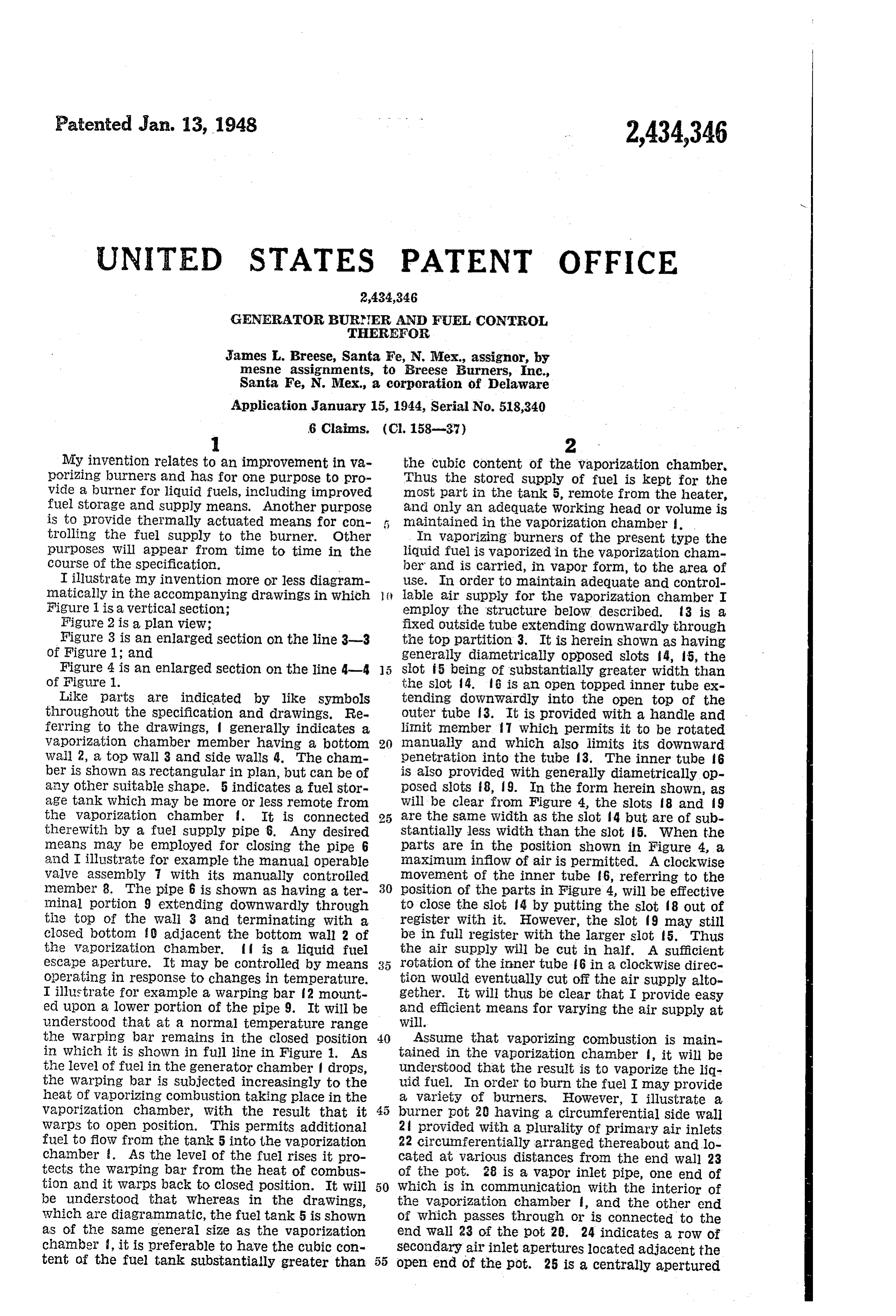
flame ring which partially closes the open end bustion will take place. The vaporized hydro of the pot. 26 is an outer skirt surrounding the carbon is initially mixed with primary air flowing pot but provided with an air inlet aperture 27 through the apertures 22. The final mixture is through which the pipe 28 passes. An ample completed by secondary air passing through the clearance is allowed for a flow of air into the apertures 24. At the high fire stage the flame space Within the skirt 26 to Supply air to the in paSSes out through the aperture of the flame ring terior of the pot through the apertures 22 and 24. 25 and into whatever combustion chamber or heat It will be understood that the burner may be con element is employed.
nected with or inserted into any suitable combus In the structure herein shown it will be under tion chamber or heating element or stove, not stood that in order to maintain combustion the herein shown. - level of fuel must be below the top of the slots It will be realized that, whereas I have de in the tube 6. If the fuel reaches the level of scribed and illustrated a practical and Operative the lower end of the passage 28, no air will be device, nevertheless many changes may be made admitted to the vaporization chamber, except to in the size, shape, number and disposition of parts 15 the very small area within the tube, and the va Without departing from the Spirit of my inven "porizing process Will cease. Normally the bar 2 tion. I therefore Wish my description and dra W will be in the closed position. Assuming that ings to be taken as in a broad sense illustrative combustion has been initiated, the result will be or diagrammatic, rather than as limiting me to a progressive lowering of the level of the fuel, my precise showing. 20 As the depth of the fuel between the generating The use and operation of the invention are as flame and the bar 2 is reduced, the bar is sub follows: jected increasingly to the heat of vaporizing com I have illustrated a vaporizing type burner bustion. It thus flexes into the open or dotted which includes in a compact unit the burner line position of Figure 1. In other words, the proper and the vaporization chamber. The 25 fuel itself constitutes a protective heat insula burner may be applied to or inserted in any Suit tion. I thus provide a modulating control for able combustion or heat radiating member such varying the fuel supply and for preventing undue as a stove, furnace, or water heater. The gen depression of the fuel level within the vaporiza erator chamber is of sufficient size to contain a tion chamber .
substantial Supply of fuel but I illustrate a sepa 30 I claim:
rate fuel tank, which may be of much larger 1. In a vaporizing burner assembly means size, together with heat responsive means for Con forming a vaporization chamber, means for con trolling the flow of the fuel from the fuel tank trollably supplying air to the interior thereof, to the vaporization chamber proper. As the level a burner in communication with the vaporiza of fuel in the vaporization chamber drops, the 35 tion chamber at a level above the level of liquid warping bar 2 becomes subjected to the heat of fuel in said vaporization chamber, means for vaporizing combustion and is thereby warped in delivering liquid fuel to the interior of the va to open position in relation to the fuel passage porization chamber from a remote source, and . After the passage is open and additional means for thermally controlling the flow of fuel fuel flows in, the level of the liquid fuel in the 40 into Said vaporization chamber, including a ther vaporization chamber rises Sufficiently to permit mally responsive member located within the va the bar 2 to cool and to Warp back to passage pOrization chamber, at a point substantially be closing position. low the maximum fuel level therein, said ther In the type of burner herein shown, the rate inally responsive member being formed and of combustion is controlled by controlling the 45 adapted to increase the fuel supply in response to air supplied to the interior of the vaporization an increase in temperature at the thermally re chamber. The air may be controlled by rotat Sponsive member.
ing the inner tube 6 by means of a handle f7. A 2. In a vaporizing burner assembly, a burner, large supply of air may be admitted at the ini means for Supplying vaporized liquid fuel to the tiating stage, When a match or lighted Waste Or 50 burner including means forming a vaporization other lighting Substance may be dropped into the chamber, means for controllably Supplying air vaporization chamber through the air passage 6 to the vaporization chamber, a vaporized fuel or through the passage 28. It must be kept in Conduit extending from the vaporization cham mind that there must be some air flow at all ber to the burner, from a level above the level of times, if continuous operation is to be maintained. 55 the liquid fuel in Said vaporization chamber, Since the only means for getting fuel into the means for delivering liquid fuel to the interior of pot 20 is to convert the fuel into a gas or Vapor, the Vaporization chamber, and thermally respon enough air must be admitted to maintain the Sive means for controlling the flow of liquid fuel Combustion necessary for the vaporization of to the vaporization chamber, positioned in the the gas. The greater the rate of air flow, the 60 Vaporization chamber at a level below the nor greater is the rate of Combustion. Air should mal level of the liquid fuel in said chamber, said be admitted in sufficient quantity not merely to thermally responsive means being formed and maintain the combustion necessary for the vapor adapted to increase the fuel supply in response ization of the fuel in the generator chamber , to an increase in temperature at the thermally but also to provide an excess supply of oxygen. 65 responsive means.
The combustion takes place adjacent the tube 3, 3. In a vaporizing burner assembly, a burner, Which in turn is adjacent the vapor inlet passage means for Supplying vaporized liquid fuel to the 28. The normal velocity of air is effective to burner including means forming a vaporization carry at least part of the flame into the interior chamber, means for controllably supplying air to of the pot 20. It is important not merely to 70 the vaporization chamber, a vaporized fuel con maintain a fuel vaporizing flame within the duit extending from the vaporization chamber to chamber but also to carry some flame and un the burner, from a level above the level of the burned oxygen into the interior of the pot so liquid fuel in Said vaporization chamber, means that, when the additional supply of oxygen is for delivering liquid fuel to the interior of the va provided through the apertures 22 and 24, com 75 porization chamber, and thermally responsive
Page 4
means for controlling the flow of liquid fuel to adapted to increase the fuel supply in response to the vaporization chamber including a heat re an increase in the temperature to which said sponsive valve member in the vaporization cham heat responsive means is Subjected. ber, said valve member being formed and adapt 6. In a vaporizing burner, means forming a ed to move to a fuel flow increasing position in 5 vaporizing chamber adapted to receive a Substan response to increase in temperature at the Valve tial volume of liquid fuel for vaporization, and member. means for controlling the flow of liquid fuel into 4. In a vaporizing burner assembly, a pot type Said chamber and thus the level of unvaporized burner, means for Supplying vaporized liquid fuel liquid fuel in said chamber, including a liquid to the burner including means forming a vapor O fuel inlet having a discharge aperture located ization chamber, means for controllably supply below the level of liquid fuel in the chamber, and ing air to the vaporization chamber, a vaporized means for controlling said inlet and thereby con fuel conduit extending from the vaporization trolling the level of unvaporized liquid fuel in chamber to the burner, from a level above the Said chamber, including a thermostatic member level of the liquid fuel in Said vaporization cham 5 normally submerged in the liquid fuel, and ber, means for delivering liquid fuel to the inte formed and adapted to admit an increased fuel rior of the vaporization chamber, and thermally Supply in response to increase in temperature at responsive means for controlling the flow of liq Said thernOStatic member. - uid fuel to the vaporization chamber, positioned JAMES L. BREESE, in the vaporization chamber at a level below 20 the normal level of the liquid fuel in said cham REFERENCES CITED ber, said thermally responsive means including The following references are of record in the a thermally responsive fuel Supply control mem file of this patent:
ber adapted to increase the rate of fuel flow in response to an increase in the temperature to 25 UNITED STATES PATENTS which said control member is subjected. Number Name Date 5. In a vaporizing burner assembly, a burner, 2,017,237 Finley-------------- Oct. 15, 1935 means for Supplying vaporized liquid fuel to the 80,590 Brockington --------- Aug. 4, 1868 burner, including means forming a vaporization 1,378,689 Larson ------------- May 17, 1921 chamber, means for controllably supplying air to 30 1778,437 Valjean ------------ Oct. 14, 1930 the vaporization chamber, a vaporized fuel con 1,412,620 Lacke -------------- Apr. 11, 1922 duit extending from an upper part of the vapor 1,833,273 Williams----------- Nov. 24, 1931 ization chamber to the burner, means for de 1858,557 Piatt --------------- May 17, 1932 livering liquid fuel to the interior of the vaporiza 1,113,966 Dunn -------------- Oct. 20, 1914 tion chamber, and thermally responsive means 1930,863 Scheu -------------- Oct. 17, 1933 for controlling the flow of liquid fuel to the wa 1,222,346 Adams ------------- Apr. 10, 1917 porization chamber, and thus the level of fuel 1,271,680 Dunn -------------- July 9, 1918 Within the Vaporization chamber, said means be 1,655,569 Scheu -------------- Jan. 10, 1928 ing positioned in the vaporization chamber at 2,134,843 Rouse --------------- Nov. 1, 1938 a level below the normal level of the liquid fuel 40 1817,069 Dickey -------------- Aug. 4, 1931 in said chamber, and being responsive to the heat 2,258,043 Brace --------------- Oct. 7, 1941 of vaporizing combustion taking place in the va 1887,514 Fiatt -------------- Nov. 15, 1932 porization chamber, and being formed and
Provenance
- Collection
- Cited prior art
- Original PDF
- patentimages.storage.googleapis.com →
- Filed
- 1944-01-15
- Pages
- 4
- Method
- pdftotext (the PDF's own text layer) + pdftoppm 300dpi page scans
- Source
- Google Patents bibliographic record
- Granted
- 1948-01-13
- Inventors
- James L Breese; BREESE BURNERS Inc
- Transcribed from
- patentimages.storage.googleapis.com →