patent · US4488951
Integrated electrochemical/chemical oxygen generating system
18 December 1984
Page 1
United States Patent (19) 11) Patent Number: 4,488,951 Nolan et al. (45) Date of Patent: Dec. 18, 1984 54) INTEGRATED (56) References Cited ELECTROCHEMICAL/CHIEMICAL U.S. PATENT DOCUMENTS
OXYGEN GENERATING SYSTEM
3,884,836 5/1975 Kihl et al. .......................... 423/579 3,887,696 6/1975 Bernard et al. ..................... 423/579 (75) Inventors: Mary E. Nolan, Topsfield; Anthony 4,061,554 12/1977 Chillier-Duchatel et al. ..... 204/129 B. LaConti, Lynnfield, both of Mass. 4,102,757 7/1978 Chillier-Duchatel et al. 204/129X
(73) Assignee: General Electric Company, Primary Examiner-Donald R. Valentine Wilmington, Mass. Attorney, Agent, or Firm-I. David Blumenfeld
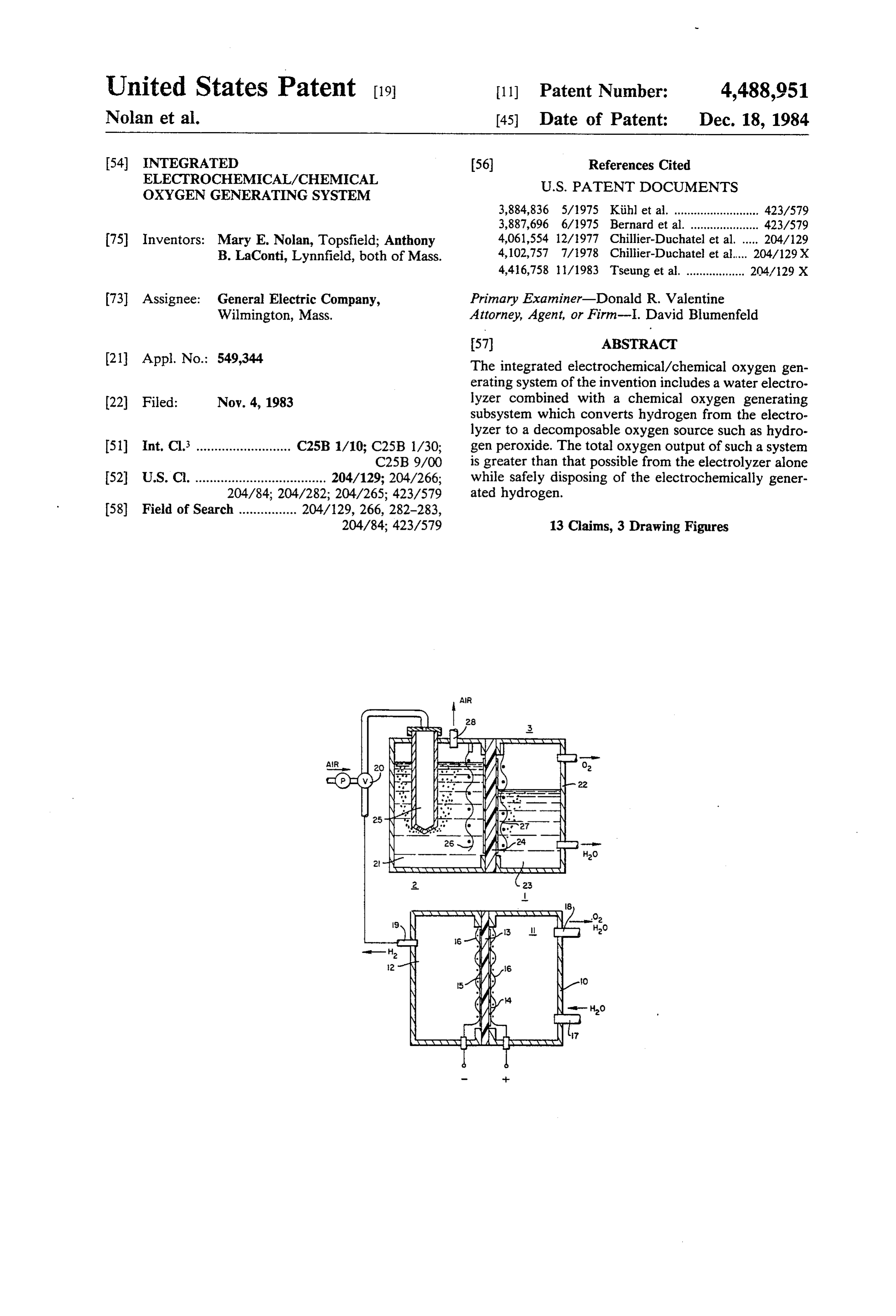
(21) Appl. No.: 549,344 The integrated electrochemical/chemical oxygen gen erating system of the invention includes a water electro 22 Fied: Nov. 4, 1983 lyzer combined with a chemical oxygen generating subsystem which converts hydrogen from the electro lyzer to a decomposable oxygen source such as hydro (51) Int, Cl. .......................... C25B 1/10; C25B 1/30; gen peroxide. The total oxygen output of such a system C25B 9/00 is greater than that possible from the electrolyzer alone 52 U.S.C. .................................... 204/129; 204/266; while safely disposing of the electrochemically gener
204/84; 42.3/579 13 Claims, 3 Drawing Figures
Page 2
Drawing sheet — no readable text.
Page 3
Drawing sheet — no readable text.
Page 4
The various objectives and advantages of the inven
INTEGRATED ELECTROCHEMICAL/CHFEMICAL tion are realized in an oxygen generating system which OXYGEN GENERATING SYSTEM includes one or more membrane electrolyzer cells in which water is electrolyzed to produce oxygen in the
This invention relates to an oxygen generating sys anode chamber and hydrogen in the cathode chamber. tem. More particularly, it relates to a hybrid system Hydrogen from the cathode chamber is combined with which includes electrolytically generated oxygen and an air stream and introduced into a catalytic reaction also oxygen generated from hydrogen peroxide formed Zone where a portion of the hydrogen is chemically by chemically reacting hydrogen from the electrolyzer. combined with oxygen in the air stream to form an Electrolysis of water is a well known process for the 10 oxygen source such as hydrogen peroxide. The remain production of oxygen. One particularly advantageous ing portion of the hydrogen is converted to water. The form of a water electrolyzer is described in U.S. Pat. hydrogen peroxide is introduced into a catalytic decom Nos. 3,992,271, and 4,039,409 assigned to General Elec position zone where it is catalytically decomposed to tric Company, the assignee of the present application. form oxygen and water. The total oxygen output of the The water electrolyzer described in these patents con 15 system is thus greater than the output from the electro sists of one or more cells each of which includes a cation lyzer alone while safely and readily disposing of the exchanging membrane that separates the cell into anode electrolytic hydrogen.
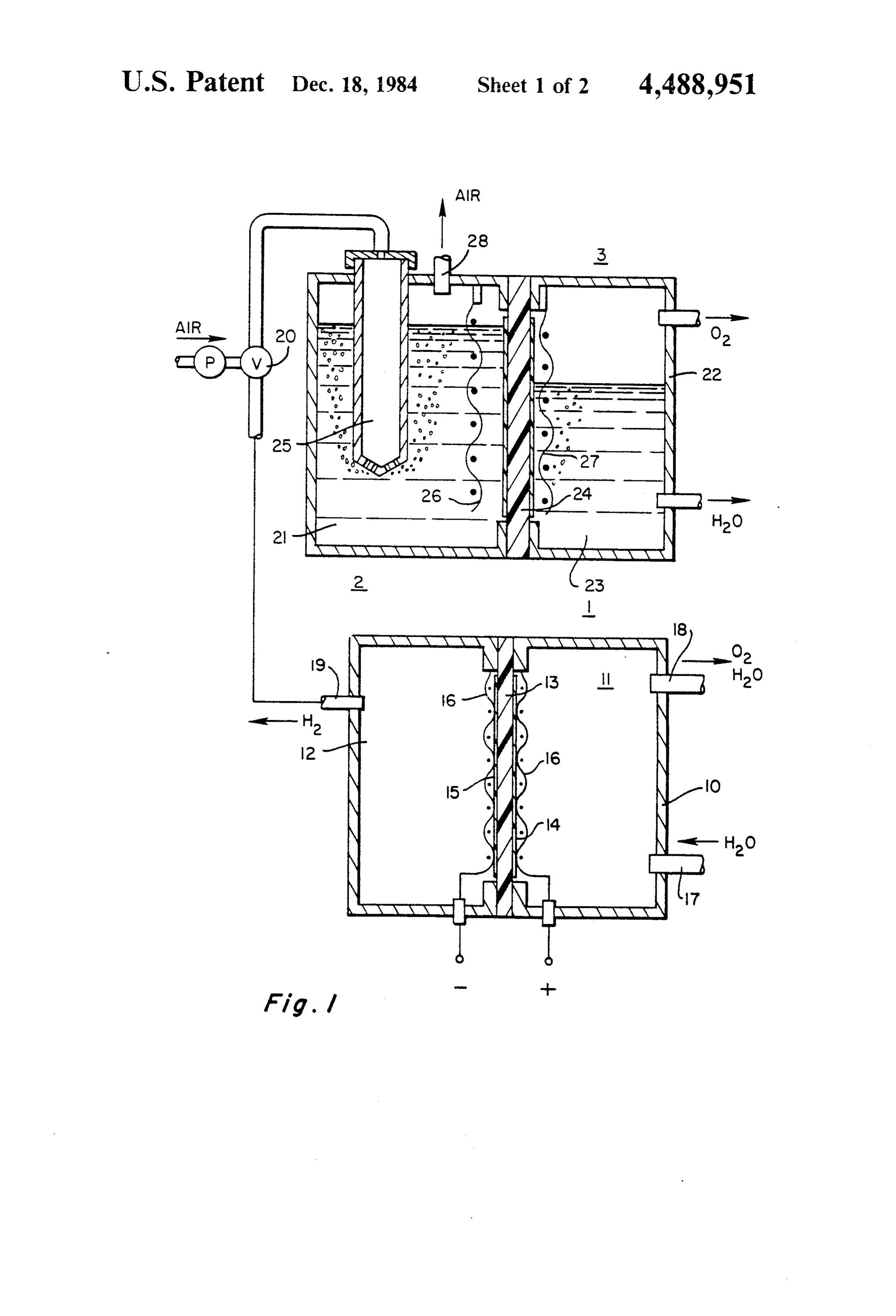
and cathode chambers. Catalytic anode and cathode The novel features which are believed to be charac electrodes are positioned in intimate contact with oppo teristic of the invention are set forth with particularity site surfaces of the membrane, with the preferred form in the appended claims. The invention itself, however, of intimate contact being bonding of the catalyst to the together with further advantages thereof may best be membrane. Water is electrolyzed in the anode chamber understood by reference to the following description to produce oxygen. Hydrogen ions produced in the taken in connection with the accompanying drawing in anode reaction are transported through the membrane 25 which: FIG. 1 is a schematic illustration of a membrane to form gaseous hydrogen in the cathode chamber.
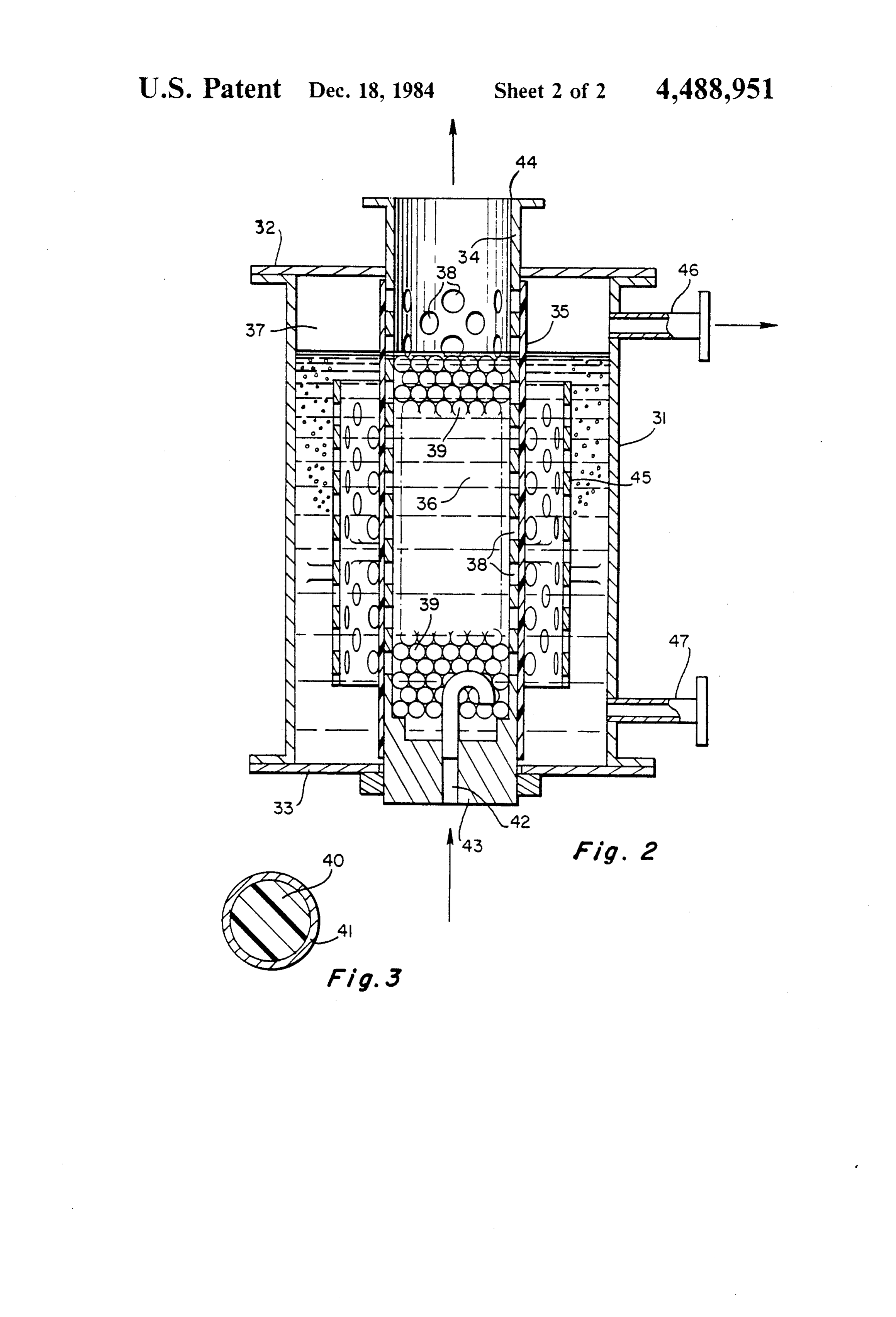
Membrane electrolyzers of this type are particularly verter electrolysis water cell coupled with a chemical con for chemically disposing of the hydrogen and useful because they do not require liquid electrolytes producing additional oxygen by chemical extraction of and because they can be operated at high current densi ties, (densities ranging from 200-2000 amp/ft.2 are com 30 oxygen from an air stream. FIG. 2 illustrates a peroxide reactor/decomposer mon) so that a relatively small and compact assembly structure useful in the integrated oxygen generator of can produce a substantial volume of oxygen.
However, where the electrolytically generated oxy FIG. 1.
FIG. 3 illustrates the catalyzed ion exchange beads gen is to be used in medical, home or similar applica used in the reactor of FIG. 2. tions, disposing of the hydrogen can be a problem and 35 FIG. 1 illustrates the integrated electrochemical/- can limit the applicability and use of electrolytic oxygen chemical oxygen generating system of the instant inven generators. tion. The oxygen generating system includes an electro Applicant has found a simple and effective solution to lyzer 1 comprising one or more cells for electrochemi the problem of safely disposing of the gaseous hydrogen cally dissociating water to produce oxygen and hydro from the electrolyzer while simultaneously increasing gen although only one cell is shown for the sake of the total oxygen output of the system. To this end, a simplicity and ease of explanation. Coupled to electro portion of the electrolytic hydrogen is used to extract lyzer 1 is reactor 2 for disposing of the hydrogen by oxygen from an air stream by catalytic conversion of converting it to hydrogen peroxide and water. Hydro hydrogen and oxygen to hydrogen peroxide with the gen peroxide formed in reactor 2 is fed to catalytic remaining hydrogen being converted to water. The 45 decomposer 3 to produce oxygen and water, with the hydrogen peroxide is decomposed catalytically to pro oxygen being combined with the output of the electro duce oxygen and water and the oxygen is used to enrich lyzer to enrich the oxygen output of the system. the oxygen stream exiting from the anode chamber of Water electrolyzer cell 1 consists of a housing 10 the electrolyzer thus producing more oxygen than is which may be fabricated of any material (such as stain possible with the electrolyzer alone. In this fashion all 50 less steel) which is resistant to the oxygen and hydrogen of the hydrogen produced by the electrolyzer cell is products from the electrolyzer. Housing 10 is divided safely disposed of and used to produce extra oxygen by into anode and cathode chambers 11 and 12 by means of chemical conversion processes. a permselective (i.e., cation exchanging) polymeric It is, therefore, a principal objective of this invention membrane 13. Anode and cathode electrodes 14 and 15 to produce an electrolytic oxygen generator in which 55 are positioned in intimate contact with opposite sides of the gaseous non-oxygen product is used to produce membrane 13 and are preferably bonded directly additional oxygen. thereto.
A further objective of the invention is to provide a The anode and cathode electrodes are preferably in water electrolyzer for providing oxygen in which the the form of bonded aggregates of catalytic particles and by-product hydrogen gas is safely disposed of. 60 a polymeric binder such as polytetrafluorethylene Still another objective of the invention is to produce (PTFE). The catalytic particles on the anode side may an oxygen generating system in which the chemical be platinum-iridium oxides, platinum-ruthenium oxides, conversion and reconversion of the gaseous hydrogen ruthenium-iridium oxides, ruthenium iridium tantalum from an electrolyzer is utilized to extract oxygen from oxides or other stable low over-voltage noble metal an air stream and to increase the oxygen output of the 65 oxides. The cathode catalytic particles are preferably system. platinum black, palladium black, ruthenium black, re Other objectives and advantages of the invention will duced ruthenium iridium oxides used alone, as mixtures become apparent as the description thereof proceeds. or with an extender such as graphite. It is to be under
Page 5
stood that there are a variety of catalytic anode and 4. Air flow through the diaphragm-from 0.02-0.06 cathode particles which may be utilized in addition to SCFM/in2 of membrane at 20 cm mercury vac those specifically described herein. .
Current collecting screens 16 of titanium niobium, or Catalytic reaction element 27 in FIG. 1 is shown as a the like, are positioned against the anode and cathode 5 woven platinum screen. However, the catalytic reac electrodes and are respectively connected to the posi tion element is not limited to screens nor to platinum tive and negative terminals of a DC power source. An catalysts. Other noble metal (high surface area) blacks inlet conduit 17 is provided to introduce water to the may be used, as may be transition metals, silver, carbon, anode chamber and oxygen and excess water are re graphite, oxides of the metals, as well as carbides, sili moved from the chamber by outlet conduit 18. Hydro 10 cides and nitrides of these metals. Alternatively, organic gen from cathode outlet conduit 19 is combined with an catalysts such as pthalocyamines or anthraquinones oxygen bearing gaseous stream, (preferably air) in a may be utilized to produce the hydrogen consuming, mixing chamber or mixing valve 20 so that the hy peroxide forming reaction. Furthermore, these catalysts drogen/oxygen mixture can be readily controlled. Pref. may be deposited on substrates of various sorts rather erably, the hydrogen is diluted with the air to form a 15 than being deposited on a screen. mixture which does not exceed four (4) volume percent A catalytic decomposition element 27 is located in of hydrogen in air. The hydrogen-air mixture is intro chamber 24 and decomposes the hydrogen peroxide to duced into reactor 21 to form hydrogen peroxide. Both form oxygen and water. It is shown as a screen having the reactor and decomposition zones are located in a decomposition catalysts deposited thereon. The decom housing 22 which is separated into reaction and decom 20 position catalysts which may be used include: position chambers 21 and 23 by a semi-permeable mem Raney nickel, MnO2, noble metal blacks, silver, Co brane 24 which has significant water, peroxide trans compounds, metallized graphite, metal carbides (BC4; port. WC2, etc.) silicides and borides. The hydrogen-air mixture is introduced into chamber The catalyst, in the reactor and decomposer, may be 21 which constitutes the first reaction zone by means of 25 Supported on Screens and various kinds of substrates, a perforated tube 25 which extends into an aqueous porous diaphragms, porous papers and the like. electrolyte solution such as 0.01N sulfuric acid con An electrolyte (acidic or caustic) either in liquid form tained in chamber 21. The mixture is bubbled through as shown in FIG. 1 or in solid form, as will be described the solution and contacts a catalytic reaction element 26 in connection with FIG, 2, is needed to cause the hydro which is shown in FIG. 1 as a woven platinum screen. 30 gen peroxide reaction to proceed properly. The pre A portion of the hydrogen and oxygen from the air is ferred reactor design is one which does not contain reacted on the screen to form hydrogen peroxide with liquid electrolytes but rather is one in which the electro substantially all of the remaining hydrogen reacting to lyte is a solid having the catalyst deposited thereon. One form water. Excess air and any residual hydrogen is example of a solid electrolyte, which will be described removed from the reactor by an outlet conduit 28. 35 in detailed subsequently, is ion-exchange beads having a Decomposition of the peroxide to produce oxygen catalyst layer deposited within and on the surface. Met and water takes place in the second or decomposition allized cation exchange beads can be prepared by ex chamber which constitutes the second or decomposi changing positive ions such as Cut , Ni, Agt, tion reaction zone although, as will be pointed out sub Pd and complex positive ions such as Pt diamino sequently, the catalytic decomposer may be separate 40 dinitrito ions, copper ammonium ions, etc. into the from the reactor. Membrane 24 which separates the beads and Subsequently reducing these metallic ions to housing into the two reaction zones or chambers is a the metallic state with suitable reducing agents such as semi-permeable membrane, such as Nafion 117, porous sodium borohydride, hydrazine and the like. Metallized polyethylene, so that the hydrogen peroxide, which is anion exchange beads can be prepared by exchanging very similar to water, is readily transported across the 45 negative ions such as chloroplatinate, PtCl6-, ion, etc. membrane. In a system where a liquid electrolyte such into anion exchangers and subsequently reducing these as aqueous Sulfuric acid is utilized in the reactor, the complex ions to the metallic state with suitable reducing water permeable membrane is preferably a cation ex agents such as listed above. changing membrane such as Nafion 117 which is perme EXAMPLE able to water and hydrogen peroxide but will be imper 50 meable to sulfate ions so that the sulfuric acid does not An integrated electrochemical/chemical oxygen gen diffuse to the decomposition chamber. erating system of the type just described was tested and Alternatively, if a solid electrolyte is utilized in the evaluated. An electrochemical water electrolyzer was reactor, the membrane may be microporous, i.e., a poly constructed consisting of three series-connected bipolar meric material having either labyrinthine pores or pores 55 cells, each having an active cell area of approximately of a non winding character. One microporous mem 0.05 ft2. Each cell was divided into anode and cathode brane of approximately 7 mil thickness is commercially chambers by means of a cation transporting membrane available from the DuPont Company under its trade of the type sold commercially by the DuPont Company name Nafion 701 and includes randomly distributed under its trade designation Nafion 120 which is an 120 labyrinthine micropores which are generally rectangu 60 equivalent weight membrane, having sulfonic acid func lar in shape and extend through the membrane. Pore tional groups and is approximately 10 mils in thickness. dimensions in Nafion 701, as measured by pressure drop The anode electrode was a bonded aggregate of 50 or mercury intrusion techniques, are as follows: weight percent platinum iridium oxide and polytetraflu 1. Cross Sectional area-one micron by 10 microns. orethylene polymeric binder particles. The cathode 2. Individual interconnectional lengths to form the 65 electrode was an aggregate of platinum black and simi labyrinthine pores extending through the mem lar binder particles.
brane-approximately 3-30 microns. The individual series-connected cells were separated 3. Void volume-40-50% by 10 mill titanium bipolar elements which contacted the
Page 6
current collectors associated with the anodes and cath any excess air or any residual hydrogen being removed odes of adjacent cells. The current collecting screens from the reactor chamber through the outlet conduit 44. which are directly connected to the positive and nega The hydrogen peroxide formed in the reactor chamber tive terminals of the DC power source were 003 gauge passes through the perforations in tubular membrane platinized titanium screens. support member 34 and into contact with the interior The electrolyzer was operated at a current of 10 amps side of the separator membrane 35. Because the reactor (current density 200 A/ft2) and yielded approximately chamber contains no liquid electrolyte (only distilled 225 cm3 of hydrogen and 113 cm3 of oxygen per minute. water), the membrane characteristics are much less The electrochemically generated hydrogen was diluted complex. The membrane need only be water and H2O2 with air to form a two (2) volume percent (%) hydro 10 permeable since it does not have to have electrolyte gen in air mixture. The mixture was bubbled through a rejection characteristics. Hence, porous membrane reactor containing a catalytic conversion element in the structures such as polyethylene, polypropylene, etc. can form of a woven platinum screen (100 mesh) having a be used in place of expensive ion exchanging mem dimension of 7.75 in. (W) by 5.75 in. (L)x 0.01 in (T). branes.
The catalytic screen was immersed in a 100 ml solution 15 A perforated decomposition catalyst support men of 0.01N sulfuric acid. A small quantity of a Ti it brane 45 is positioned in decomposition chamber 37 and solution was added to the acid electrolyte to serve as a attached to the semi-permeable membrane or the walls visual indicator for the production of hydrogen perox of the housing by means of a plurality of radially ex ide from the catalytic reaction of the electrochemically tending vanes. Support element 45 has catalytic mate generated hydrogen and air mixture on the platinum rial deposited on the surfaces thereof whereby hydro screen. The mixture was bubbled through the dilute gen peroxide permeating through membrane 35 is de acid solution with the Ti indicator for 24 hours composed into oxygen and water. The oxygen perme and the quantity of peroxide formed was measured ates upward through the distilled water in the decompo using spectrophotometric techniques. It was found that sition chamber and is removed from the decomposition approximately 0.03% of the electrochemically gener 25 chamber through the decomposer outlet conduit 46 ated hydrogen was converted to peroxide with the while the distilled water in the decomposer may be remainder going to water or remaining unreacted. A removed through a decomposer water outlet conduit portion of the peroxide solution was then transmitted to 47. The oxygen from the decomposer, as pointed out a decomposition chamber containing a platinum black previously, is combined with the oxygen from the water catalyst deposit on a graphite substrate and the hydro 30 electrolyzer to provide additional oxygen, i.e., the oxy gen peroxide was readily decomposed to water and gen outlet from the electrolyzer is enriched by the oxygen in the catalytic decomposer. amount of oxygen extracted chemically from the air FIG. 2 illustrates an integral reactor-decomposer stream by hydrogen from the electrolyzer. More impor structure which is characterized by the use of catalyzed tantly, however, by means of these structures and the ion exchanging beads as the electrolyte. The reactor is 35 overall arrangement the electrolytic hydrogen is safely separated from the decomposer by means of a water and efficiently disposed of thus opening up applications permeable membrane which permits the peroxide to for the use of electrolytic oxygen producing Systems diffuse into the decomposer reaction zone or chamber. where the disposal of the electrolytic hydrogen can The reactor/decomposition structure of FIG. 2 in present a problem.
cludes a tubular housing 31 which is closed at the top 40 While the instant invention has been shown and illus and bottom by means of the upper and lower cover trated by means of certain preferred embodiments plates 32 and 33. Extending through the center of the thereof, the invention is by no means limited thereto housing is a perforated, tubular member 34 which sup since other modifications of the instrumentalities and of ports a tubular water and hydrogen peroxide permeable the steps of the process may be made and still fall within membrane separator 35. The tubular membrane support 45 the scope of the invention. It is contemplated by the and the membrane divide the housing into two concen appended claims to cover any such modifications that tric chambers, one being the inner reactor chamber 36 fall within the true scope and spirit of the invention. and the other being the outer or decomposition cham What is claimed as new and desired to be secured by ber 37. Letters Patent of the United States is: The walls of the tubular membrane support 34 are SO 1. A process for generating oxygen including the provided with holes or perforations 38 which begin a steps of:
short distance below cover 32 and extend to the bottom (a) electrolyzing water to produce oxygen in the of the support member. Positioned in reactor chamber anode chamber of a cell divided into anode and 36 are a plurality of catalyzed ion-exchange beads 39 cathode chambers by a cation transporting mem which are immersed in distilled water. The catalyzed 55 brane;
ion-exchange beads, as may be seen most clearly in FIG. (b) forming gaseous hydrogen by reduction of hydro 3, consist of polymeric ion exchange beads 40 of the gen ions in the cathode chamber of the cell; type sold by Illinois Water Treatment under the desig (c) removing the hydrogen from the cathode cham nation TC-2, covered by a thin catalytic surface layer 41 ber;
which is deposited on the ion exchanging beads in the 60 (d) providing an oxygen containing gaseous stream; manner previously described. (e) chemically converting the electrolytically pro The hydrogen air mixture is brought into the reactor duced hydrogen with oxygen from the said oxygen chamber and into contact with the catalytic beads by containing gaseous stream to form hydrogen per means of a gas mixture inlet tube 42 which extends oxide;
through a closure plug 43 which extends through bot 65 (f) chemically decomposing the hydrogen peroxide to tom plate 33. The hydrogen air mixture in passing up form oxygen and water;
wardly through the bed of catalyzed ion exchange (g) recovering both the electrochemically produced beads reacts to form hydrogen peroxide and water with oxygen and the chemically produced oxygen as
Page 7
product whereby the electrochemically produced 10. The process according to claim 8 wherein the hydrogen is safely disposed of and additional oxy hydrogen peroxide is removed from the first reaction gen is produced by chemical extraction thereof zone by permeation through a water permeable mem from an oxygen containing gas stream. brane.
2. The process according to claim 1 wherein the 11. The process according to claim 8 wherein hydro electrochemical reactions in the anode and cathode gen and the oxygen bearing stream are simultaneously introduced into said first reaction zone.
chamber take place at electrodes which are in intimate 12. An oxygen generating system comprising: contact with the membrane. (a) a water electrolysis cell comprising: 3. The process according to claim 1 wherein the 10 (1) a housing, oxygen containing stream is air. (2) a cation transporting membrane dividing said 4. The process according to claim 1 wherein hydro cell into anode and cathode chambers, gen and the oxygen containing gas stream are brought (3) anode and cathode electrodes in intinate into contact with a catalyst to form hydrogen peroxide. contact with opposite sides of said membrane, 5. The process according to claim 1 wherein hydro 15 (4) inlet means for introducing water into said gen and the oxygen containing stream are exposed to a anode chamber and outlet means for removing catalyst in the presence of an electrolyte. gaseous Oxygen, 6. The process according to claim 5 wherein the (5) means for removing gaseous hydrogen from electrolyte is an aqueous electrolyte. said cathode chamber, 7. The process according to claim 5 wherein the 20 (b) chemical conversion means coupled to the cath electrolyte is a solid and is in contact with said catalyst. ode chamber for disposing of the gaseous hydrogen 8. A process for generating oxygen comprising: and extracting oxygen from an air stream, includ (a) electrochemically forming gaseous oxygen from 1ng:
water by oxidation at an anode electrode in a mem 25 (1) a first catalytic reaction zone for converting a brane cell and forming gaseous hydrogen by reduc portion of the gaseous hydrogen and oxygen tion at the cathode electrode of said cell, from air stream to hydrogen peroxide, said cata (b) chemically disposing of the hydrogen gas by ex lytic reaction zone containing catalytic means traction of oxygen from an air stream including: and electrolyte means in contact with said cata 1. chemically combining at least a portion of said 30 lytic means, hydrogen with oxygen from said gas stream (2) a second catalytic reaction zone downstream through a catalytic reaction in a first reaction from said first zone for converting the remaining zone to form hydrogen peroxide, gaseous hydrogen and oxygen from the air stream to water, 2. chemically combining the remainder of said (3) means for removing hydrogen peroxide from hydrogen with oxygen from said gas stream to 35 said reaction zone including membrane means form water, permeable to water and hydrogen peroxide (c) catalytically decomposing the hydrogen peroxide (c) a catalytic decomposer coupled to said converter to form oxygen and water in a second reaction for decomposing the hydrogen peroxide to gaseous ZOne, oxygen and water, (d) enriching the electrochemically produced oxygen 40 (d) means for combining the electrochemical and with the chemically produced oxygen. chemically produced oxygen. 9. The process according to claim 8 wherein the 13. The oxygen generating system according to claim membrane cell is divided into anode and cathode cham 12 wherein said anode and cathode electrodes are bers by means of a gas and liquid impermeable cation bonded to opposite sides of2. saidk membrane. exchange membrane. 45 zk :k
Provenance
- Collection
- Cited prior art
- Original PDF
- patentimages.storage.googleapis.com →
- Filed
- 1983-11-04
- Pages
- 7
- Method
- pdftotext (the PDF's own text layer) + pdftoppm 300dpi page scans
- Source
- Google Patents bibliographic record
- Granted
- 1984-12-18
- Inventors
- Mary E. Nolan; Anthony B. LaConti; General Electric Co
- Transcribed from
- patentimages.storage.googleapis.com →